Cornell University
Electrical Engineering 476
Video Generation
with Atmel Mega644/1284 and GCC
Introduction
A television (TV) monitor is a good example of a device which needs hard-realtime control. The TV is controlled by periodic synchronization (sync) pulses. If a sync pulse is late, the TV picture quality suffers. So a late calculation is worth nothing. The Atmel AVR mcus are fast enough to generate black and white (but not color) sync and image content, as long as you obsessively pay attention to the time required for every operation. Note that the newest code is here.
Small TV monitors also seem to be one of the cheapest graphics devices you can buy, include audio amplifiers and speakers, and are designed to be almost bullet-proof. A perfect lab device.
Video Generation
There are several very good references for understanding how TVs are controlled by a pulse sequence. I particularly liked the Stanford EE281 Handout #7 entitled "TV paint". Also very useful were Software generated video, by Rickard Gunée, Video Tutorials by Glen A. Williamson, and various excellent projects by Alberto Riccibitti. Mark Oreglia, Professor, Department of Physics at The University of Chicago and The Enrico Fermi Institute was kind enough to allow me to post a full interlaced, NTSC sync driver.
The goal is to generate non-interlaced, black and white video,
with enough image content to be interesting as a graphics device. The software
described here implements an NTSC-rate, non-interlaced, video signal. For ease
of teaching, I wanted as much of the code as possible to be in C, with litttle
or no assembler. The current version of the code is entirely in GCC, with no assembler.
There are several versions with different horizontal and vertical resolution. See the examples below. There are utilities for drawing lines, points, and text, and for reading
back the screen color. The raster generation code needs to run fast to get good
pixel density. Once the TV gets to the bottom line displayed (ScreenBot), there is some extra time to do
computations, interact with users, or update state. All drawing must be done
when TV scan lines are not actually being drawn to avoid visual artifacts. Synchronization is handled by the two ISRs. Drawing is
done by writing bits (pixels) into the main screen array, while
the array is not being displayed. The drawing utilities described below write
to screen memory for you.
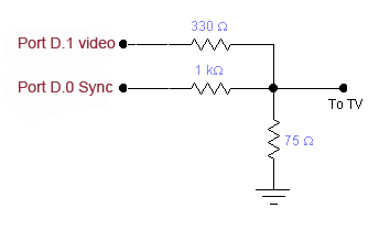
Video DAC
Two bits of a port are used to generate three video levels:
The circuit shown below connects the Mega644/1284 to the TV.
Video code using the USART as a pixel shift register (On Mega1284)
The code is sets the USART into MSIPM mode (SPI master mode) which turns off start/stop bits. The USART transmit-double-buffer makes it possible to stream pixels at a uniform rate without assembler, just by writing a fairly fast loop. With a 16 MHz crystal, the pixel rate is 4 MHz. The SYNC signal is now on pin D.0 and the video on pin D.1. There are 3 versions with formats 144x150, 160x160 or 160x200, but other values are possible. This code also uses a separate timer interrupt to put the MCU to sleep so that main does not have to. The result is that application code can run faster because frame calculations do not have to be precisely timed to fit between frames.
Program Organization
The programs haveseveral parts:
Video content API
void video_pt(char x, char y, char c) |
Draw a point into video memory. Specify the position x,y (y increasing downward) and the color with black=0, white=1, and xor=2. You can draw about 500 points in one frame time. See examples below for allowed x,y ranges. |
char video_set(char x, char y) |
Read back a point from video memory. A white point will read back as a nonzero value (actually the bit within the video memory byte which is being checked). |
void video_line(char x1, char y1, char x2, char y2,
char c) |
Draw a line into video memory. The line extends from (x1,y1) to (x2,y2) with a color as above. Uses a Breshenham algorithm for speed. You can draw about 500 points worth of lines in one frame time. |
void video_putchar(char x, char y, char c) |
Draw a 5x7 character at (x,y) with ascii character code c. The coordinates represent the upper-left corner of the character. You can draw about 16 5x7 characters in one frame time. |
void video_smallchar(char x, char y, char c) |
Draw a 3x5 character at (x,y) with character number c. The x coordinate must be divisible by 4. The coordinates represent the upper-left corner of the character. You can draw about 200 3x5 characters in one frame time. |
void video_puts(char x, char y, char *str) |
Draw a 5x7 string starting at (x,y). The coordinates represent the upper-left corner of the first character. You can draw about 16 5x7 characters in one frame time. |
void video_putsmalls(char x, char y, char *str) |
Draw a 3x5 string starting at (x,y). The x coordinate must be divisible by 4. If it is not, it will be rounded down.The coordinates represent the upper-left corner of the first character. You can draw about 100 3x5 characters in one frame time. |
Older Examples using assembler in the ISR, but more flexable bit-generation
For the most part, you should not have to mess with any of the code before
the main routine in the examples below. If you need to perfrom some fast function
15,750 times/sec (perhaps sample the A/D converter to make a digital scope),
you could put code at the end of the timer1 ISR. For all examples, be sure to set the GCC project configuration (in the Project:ConfigureOptions... menu) to:
In the examples below, there are various resolutions available. Higher resolution uses more RAM and takes more time to refresh the TV (60 times/sec). There are formats which have higher resolution horizionally or vertically. There are 16 and 20 MHz versions. In the 16 MHz versions, there is a one or two cycle inaccuracy in the width of pixels. This slight inaccuracy is usually not noticable. Using a 20 MHz crystal allows pixel-exact timing (or higher horizontal pixel density) and more cycles for building applicaitons. You can choose the format appropriate to your task.
All of the examples require the 8:8 fixed point multiply routine.
0≤x≤143 and 0≤y≤199. Note that there is a small timing compromise which causes slightly uneven pixel widths, which is fixed in the 20 MHz version. 
0≤x≤191 and 0≤y≤149. Note that there is a small timing compromise which causes slightly uneven pixel widths which, is fixed in the 20 MHz version. 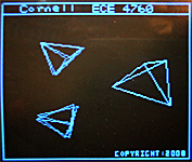
Video code modified to use the USART as a pixel shift register (On Mega644 at 20 MHz)
This version of the code is sets the USART into MSIPM mode (SPI master mode) which turns off start/stop bits. The USART transmit-double-buffer makes it possible to stream pixels at a uniform rate without assembler, just by writing a fairly fast loop. With a 20 MHz crystal, the pixel rate is 5 MHz (up from 4 MHz for the assembler code). The SYNC signal is now on pin D.0 and the video on pin D.1. The format is 192h x 150v, but could be set to other values. This code also uses a separate timer interrupt to put the MCU to sleep so that main does not have to. The result is that application code can run faster because frame calculations do not have to be precisely timed to fit between frames. A 160h x 160v version has a better aspect ratio and leaves about 800 bytes of RAM free. With more memory, the pixel rate could be set to 10 MHz for a very dense horizontal display.
Copyright Cornell University June 26, 2012