Starfox FPGA
Introduction
Our project was an attempt to implement Starfox from the Super Nintendo Entertainment System (SNES) on the FPGA using the VGA running in 320 pixels by 240 pixels screen resolution. The source of the project idea is from the classic game Starfox on the SNES. This was one of the first games to display 3D models. Figure 1 below shows a screenshot of the original game as it appeared on the SNES.
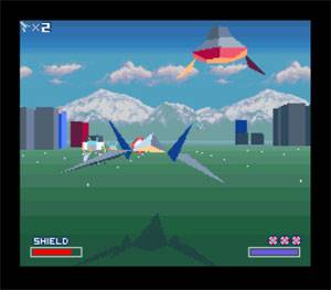
Figure 1 - Nintendo's implementation of the game
High Level Design
Logical Design
In our implementation, the 3D models are drawn in Matlab the vertex list is generated from a script. The vertex list is included as a header file in the software and the software running on the NIOS CPU communicates these 3D world coordinates to the hardware. The hardware transforms the 3D world coordinates to 2D screen coordinates using matrix arithmetic and draws the wire frame of the 3D models on the 2D VGA screen using the Breshenham algorithm implemented in Lab 2. The NIOS console then takes input from the keyboard and redraws the screen with coordinate changes to give the impression of movement for the ship.
Background Math
In order to convert a world coordinate to screen coordinates, we need to multiply the world coordinates by the camera transform matrix, called Tcam.
![]()
The total camera transformation matrix Tcam is defined as the view matrix Tview multiplied by the perspective matrix Tpersp.
![]()
Where the view matrix is a 4x4 translate matrix multiplied by a rotate:
Where N is the view vector defined as:
![]()
And V is the vector perpendicular to N that is defined as:
![]()
This is
then normalized: ![]()
And U is the right vector defined as the cross of the norms of the N and V vectors.
![]()
The perspective matrix is:
Where d is the distance from camera to near clip plane, f is the distance from the camera to the far clip plane, and h is the height of the view volume.
After the screen coordinates are calculated, they may still not be ready for a direct mapping onto the VGA screen. This is because the vertex list range is typically in the unit sphere range of -1 to 1. In order to get these coordinates into a format more suitable to the VGA, we need to multiply and shift the screen coordinates into the correct 320x240 screen range from the vertex list range.
Program & Hardware Design
Software Design
The software design and implementation is relatively simple. The vertex lists and face lists of the 3D models that are generated from Bruce Land’s MATLAB script are stored in the header files and loaded onto the NIOS CPU. This is done so that all of the necessary data would be loaded onto the FPGA and therefore there would not be any need for the FPGA to have to communicate with the base computer, which would have undoubtedly incurred more synchronization problems.
The code iterates through the vertices based on the face list and sends pairs of coordinates to the hardware, which draws a line with those vertex endpoints. The vertices are only sent when the hardware is ready and in a waiting state, indicated by the hardware ready bit which is read by the software before each attempt to send the next pair of coordinates. Also, 10 µsec sleeps were added in the loop before each pair of vertices are iterated through in order to correct some visual artifacts that were occurring on the hardware side.
The user interface was also implemented in software using the NIOS II console for the user to input movement directions. The w, a, s, d keys are used to move the model up, left, down and right, respectively. Since the Nios II C only supports getchar() and not getche(), each key press must be followed by a return to register. This does impair game play and would require an extension to the Nios II C that implements getche() to work around the limitation.
Hardware Design
The hardware reads pairs of points from the software, transforms them from the world coordinate system to the VGA screen coordinate system in 320x240 pixel resolution, and uses a breshenham line generator to draw lines between the pairs of points, forming the wire frame 3D models.
For our number system in verilog, we used a 6:12 fixed point system with 6 bits of integer precision and 12 bits or fraction precision. This was done in order to have a wide enough integer range as required by the transform parameters along with a precise enough fraction range for the conversions. The range goes from -32 to 31.9996 with increments of 2-12.
Since we planned for all the matrix multiplication to be done in verilog in order to take advantage of the hardware’s speed over the software, we wrote multiplication modules in verilog for our given number system. We started by modifying Bruce Land’s 2:16 fixed point multiply module so that it would now represent a 6:12 fixed point multiply, and then we used that multiply module as the building block for 3x3 and 4x4 matrix multiply modules. Since the addition has no special overflow case to consider, we used the standard verilog adders by using “+” when we wanted to add two numbers together, such as in computing the results of a matrix multiply.
Figure 2 - The Hardware State Machine
The actual work on the hardware end was all taken care of by a state machine (shown above in Figure 2) in verilog which would idle in a waiting state with a ready flag at logic level “1” until it received a command from the software. Upon receiving a pair of points from the software, the ready flag is set to logic “0” to communicate to the software that the hardware is busy operating on a set of points and is not ready to receive the next pair of coordinates. The state machine then goes to state “trans1” followed by “trans2” which together apply the world-to-screen matrix transforms. The transforms are implemented in verilog using the described background math and matrix multiplication modules. After state “trans2”, the coordinates are now screen coordinates and are sent to the breshenham line generator state machine. The breshenham line generator state machine would then draw a line between the pair of screen coordinates and then return to the waiting state and set the ready flag to logic “1” again.
Hardware / Software Tradeoffs
The only significant tradeoffs that could’ve been made are where the mathematical matrix transformations could be made. They are best done in hardware for speed, but require a fixed point number system to do calculations and require conversions. If done in software, the transformation may not be fast enough, but it’s much easier to handle the representations and the arithmetic. Toward the end of the project, we decided to move all the mathematical transformations out of both software and hardware in favor of pre-calculating the data in Matlab in an attempt to try to show something presentable on the screen and in order to debug our VGA drawing scheme. For this, the resultant 2D screen coordinates were included as header file to the C code.
Things We Tried That Didn’t Work
As we’ve just described, we had originally planned for the 3D world coordinate to 2D screen coordinate conversion to occur in hardware. However, the matrix multipliers that we had written in verilog did not work for a reason we had yet to figure out from many hours of debugging. At a certain point, we decided to give up on the hardware conversion and thought of moving the conversion to software and just send the 2D coordinates to the hardware. However, after some thought we decided it would be too slow in software and decided to let Matlab do the work and use the 2D coordinates directly. Figure 3 below shows the final logical diagram that was implemented as a minimum, simplified system.
Figure 3 - The Simplified System
The following parameters were used to derive Tcam, which we hard coded for now. If we wanted some user interface to move the camera around, we would need to move the math into software in order to dynamically recalculate Tcam. For our final simplified model, all the math and calculations are done in Matlab and hardcoded into the software/hardware. This required us to write a conversion script to convert numbers from decimal notation in Matlab to our 6:12 fixed point notation in verilog in order to hardcode them into verilog. All of the following parameters were chosen using a desirable view in Bruce Land’s Matlab gui and then outputting the respective variables.
LookFrom = [.5 2.5 5]
LookTo = [.5 .5 .5]
UpVector = [0, 1, 0]
d = 4
f = 10
h =.7
![]()
![]()
![]()
This Tcam matrix was then hardcoded into verilog, effectively reducing the amount of calculation we had to do in verilog at the cost of locking our camera position.
We had also tried a different approach to transforming 3D world coordinates to 2D screen coordinates from the Wikipedia page until Bruce directed us to his page.
In the Wikipedia approach:
Ax,Ay,Az = a point in 3D space
Cx,Cy,Cz = the location of the camera - hardset to 0,0,0 for now
Tx,Ty,Tz = the rotation of the camera - hardset to 0,0,0 for now
Ex,Ey,Ez = the viewer position in camera space
Bx,By = 2D projection of A
![]()
![]()
However, we did not know what to set some of the parameters to, so we went with Bruce’s already implemented transformations instead.
Relationship to Standards
Our design is a software and verilog implementation on prototyping hardware and therefore must adhere to FCC standards and regulations. Since our Dell laboratory PCs, the Altera DE2 board, and the VGA monitor all adhere to the standards, we assume that our project does as well, since we have done nothing that would cause any of our equipment to malfunction.
Copyright Considerations
The original inspiration for our design, Starfox, is copyrighted by Nintendo. However, we simply use their game as an inspiration for what could be done with the FPGA in a strictly educational manner, and therefore do not believe that there is any copyright infringement.
Safety & Usability Considerations
Our project has no safety or usability restrictions beyond those of normal computer use, since our project is interfaced through the standard keyboard, mouse, and monitor of a common desktop computer.
Results
Our design did not manage to come anywhere near Nintendo’s implementation. Figure 4 shows our wireframe models drawn on the VGA screen.
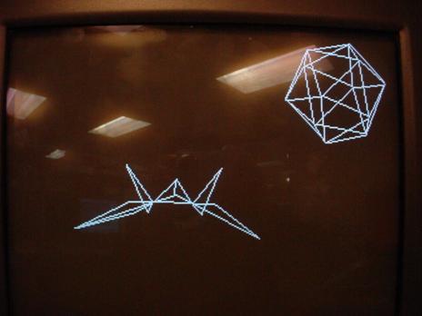
Figure 4 - Our Result
A major drawback is that there is not much user interaction at all. The user is able to slightly move the ship, but since the matrix transforms were never successfully implemented it does not give the user any 3-dimenional feel and instead simply moves the ship around the screen in 2D. There is an asteroid that is drawn at the top right of the screen that always moves down and you can try to avoid it, but at the same time there is no collision detection so moving the ship into the asteroid doesn’t actually do anything. On top of all this, the clear screen doesn’t consistently work so sometimes you see after images of the ship and/or asteroid at their previous positions. Figure 5 shows an example of the after-image artifacts.
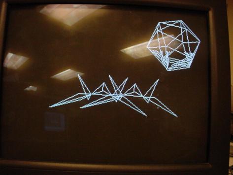
Figure 5 - The After-Image
You’ll have to manually hit KEY3 to fully clear screen if these artifacts occur. Figure 6 shows what the movement of the ship to the right should look like if no after-images occur.
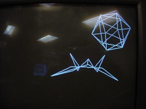
Figure 6 - The Proper Drawing of Movement
Conclusions
Our design fell vastly short of most of our expectations. When we first started, we had the goal of displaying the Starfox ship and moving it through the 3D environment on the 2D screen. As it stands, our design only has a ship and an asteroid drawn on the screen in 2D, so there is no 3D environment for the ship to move through. A lot more can be added such as moving camera positions, sharper movement, collision detection, solid plane instead of wire frame, etc. Despite our shortcomings, we still learned a lot and would like to thank Bruce Land for all his help and advice as we tried to get a stronger implementation of this project working.
Tasks
Zi Ling – Design, debugging and testing of the hardware and software, design and implementation of the simplified system, and the first draft of the project web page.
Heman – Early design, debugging, and testing of hardware and software, as well as the final draft of the project web page.
References
Outside Code Sources
The Matlab scripts to generate 3D polygon models and calculate the matrix transformations are from Prof. Bruce Land.
http://www.nbb.cornell.edu/neurobio/land/PROJECTS/Hierarchy/
The breshenham line generator code is our implementation from Lab 2.
The template for our 6:12 multiply module was Bruce Land’s 2:16 multiply module.
http://instruct1.cit.cornell.edu/courses/ece576/DDA/index.htm
The template for our verilog code was the Altera DE2 Top Level Module.
The template for our c-code was the microC/OS implementation from Lab 3.
Information References
Wikipedia for some 3D projection information
http://en.wikipedia.org/wiki/3D_projection
The Star Fox Series Wikipedia page
http://en.wikipedia.org/wiki/Star_Fox_%28series%29
Information regarding the Breshenham algorithm
http://graphics.idav.ucdavis.edu/education/GraphicsNotes/Bresenhams-Algorithm.pdf
Altera Documentation page for the DE2 Board
http://www.altera.com/education/univ/materials/boards/unv-de2-board.html
Attached Code
Our verilog and c-code has been attached in the following zip file for convenience. The zip file also includes Bruce Land’s Matlab scripts which we used to create a model of our asteroid and which we used to find the mathematical matrices, as well as our own matlab script double2fixed.m