Introduction

Our final project is a full hardware UDP (User Datagram Protocol) stack for the DE2 evaluation board that interfaces with the DM9000A MAC/PHY chip on the board. It includes the full IPv4 protocol and the ARP protocol for MAC address resolution. Our hardware interfaces with the DMA9000A using the DE2_NET software included on the DE2 CD and instantiated on a NiosII. We then instantiated a simple application that would show off all the features of our UDP stack.

High Level Design

Since the DE2 board has an Ethernet port and controller on board, we figured it would be useful to leverage it. We decided that it would be helpful for potential future ECE 576 projects to build the underlying UDP structure so students in future years could use it to interface their DE2 with data from a computer on a network. Since UDP is a simpler transport-layer protocol than TCP and is perfect for data that needs low reliability but higher speeds (such as streaming audio, etc.), we decided that it would be right scope to implement in this project.

The UDP stack and its layered nature lends itself very nicely to clean and modular code. We have a separate module that implemented each layer in each direction (transmit and receive). This is shown in the following diagram:

If the application on the FPGA (currently a simple application that just sends packets, but future users of this code will want to implement something bigger and better) wants to send a UDP packet out over Ethernet, it sends the data into the udp_send.v module in hardware, which encapsulates the data with a UDP header including a port number. This is then sent into IP_send.v, which adds the IP header (including the checksum), and then finally into the send_buffer, which manages all the outgoing packets and sends them one at a time into the NiosII. Here is where we modified the DE2_NET code that was included on the DE2 CD, which interfaces with the DM9000A. The C code running on the NiosII encapsulates the IP packets in a MAC header and sends the ensuing frames out to the DM9000A.

Packets can also be sent into the DE2. When a packet comes in through the Ethernet port, it goes straight to the DM9000A and then into the NiosII software interface. This determines whether the frame is IP or ARP, strips off the MAC header and sends the packet appropriately into our hardware. It is received by the recv_buffer.v module, which manages the flow control throughout the rest of the receive end of the hardware. IP packets are then send to IP_recv.v, which strips the IP header, calculates the checksum, and if correct, sends it on to udp_rcv.v. This takes the UDP header off and sends the data along with the source port number into the application. All of these Verilog modules are connected through another module called toplevel.v which connects directly to the DE2_NET.v file that also connects the NiosII via SOPC builder.

Our logical structure also includes implementation for Address Resolution Protocol (ARP). If we do not know the MAC address that belongs to a destination IP, we can send out an ARP packet using arp_send.v, which then travels through the send_buffer.v module that was explained earlier. We also can receive ARP packets using arp_rcv.v, which can in turn send out replies to ARP requests from other machines. The protocol is explained in further detail in the Design section below.

We decided to use the software DM9000A interface that came on the DE2 CD because the chip seemed to interface well with the software when we first tested it. We then implemented the rest of the protocol in hardware for speed purposes, to better interface with hardware elements, and for a bigger challenge for us. Also, hardware is cool.

Our design obviously has a strong relationship with the Internet protocol suite developed by the IETF (Internet Engineering Task Force). It is meant to implement these standards exactly, so when we were designing our system, we had to make sure that we knew the standards very well, or else we would not be able to communicate correctly with other network devices.

Standards

We used several standards for our project, including the IPv4 IP protocol, the User Datagram Protocol (UDP), and Address Resolution Protocol (ARP). IP is defined as a network layer protocol, while UDP is a transport layer protocol. The UDP packet is encapsulated within the data section of an IP header. The ARP protocol is used when only the network layer (IP) address is known and a hardware address must be found.

IPv4

The IPv4 data packet is sent over the network layer and consists of an IP header and the IP data. The header's minimum length consists of five words that encode information about the data being sent.

For our project the following fields were set:

Word 1:

Version: 4 (for IPv4)

Header Length: 5 words (did not encode any options)

Type of Service: 0 (set for normal delay/throughput/reliability)

Total Length: Variable with the length of packet (in bytes)

Word 2:

Identification: Unique to the packet. Started at 0 base, incremented by 1 for new packets sent

Flags: 2 (don't fragment)

Fragment Offset: 0 (no fragments)

Word 3:

Time to Live: 0x40 (number of hops before packet is discarded)

Protocol: 0x11 (for UDP)

Header Checksum: Unique to packet. Calculated by calculating one's complement of all half words in the header (not including checksum field) and then one's complementing the result

Word 4:

Source Addr: address of requesting process

Word 5:

Destination Addr: address of destination process

We did not include support for the options field in our project.

UDP

Data from the network layers IP packet's data section gets passed to the UDP transport layer. The UDP packet is therefore encapsulated within the IP packet data segment. The first two words of the UDP packet consist of the UDP header while the rest is the data. The header breaks down as follows:

Word 1:

Source port: Sending port

Destination port: Destination port of the data

Word 2:

Length: Length in bytes of entire packet

Checksum: Not required and not used in our project

Rest of UDP packet is data.

ARP

ARP request and reply packets are sent as needed to and from our DE2. When used in conjuction with IPv4 and standard 48-bit MAC addresses over Ethernet, a packet has 7 32-bit words and looks like this:

Word 1:

Hardware type: Type of hardware being used. The value for Ethernet is 1.

Protocol type: The value for IPv4 is 0x0800.

Word 2:

Hardware length: Length in bytes of hardware (MAC) address. For Ethernet, this is 6.

Protocol length: Length in bytes of logical (IP) address. For IPv4, this is 4.

Operation: (16 bits) This value is 1 for a request and 2 for a reply.

Word 3:

SHA (first 32 bits): The first 32 bits of the Sender Hardware Address (the source MAC address).

Word 4:

SHA (last 16 bits): The last 16 bits of the Sender Hardware Address.

SPA (first 16 bits): The first 16 bits of the Sender Protocol Address (the source IP address).

Word 5:

SPA (last 16 bits): The last 16 bits of the Sender Protocol Address.

THA (first 16 bits): The first 16 bits of the Target Hardware Address (the destination MAC address). This is all zeros if the packet is an ARP request packet, since the destination MAC is obviously unknown.

Word 6:

THA (last 32 bits): The last 32 bits of the Target Hardware Address.

Word 7:

TPA: The Target Protocol Address (the destination IP address).

Program/Hardware Design

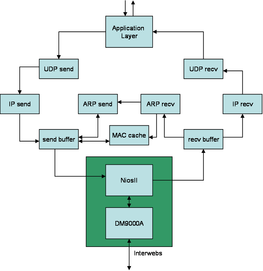
For our project, we implemented the UDP/IP and ARP protocols in hardware. Our design as implemented accepts packets from an Ethernet cable connected to the Altera DE2 board. On the board, a packet gets routed from the Ethernet cable through the DM9000A hardware module given by Altera and then through the NiosII CPU.

Receiving packets from the NiosII:

recv_buffer module:

When receiving packets, we assume that the entire packet is not sent continuously from the NiosII. To address this issue, we interface our recv_buffer module with the NiosII by implementing a handshaking protocol. When a packet chunk is received, the recv_buffer module will decode whether the packet is IP or ARP and then pass the data onto the appropriate module (either arp_recv or IP_recv). After receiving and sending the data packet, the recv_buffer module sends an acknowledge back to the NiosII and waits for the data chunk to come from the NiosII.

IP_recv module:

The IP_recv module does several things. It accepts data from the recv_buffer when the incoming valid bit is set high. However, the data does not simply get routed through this module. An IP packet consists of both a header and data section. At least the first five words of an IP (we are assuming that the packets received are IPv4 version) packet consist of the header of the packet. The first word consists of the total length of the packet. The second word contains the IP identification number. The third word specifies the protocol being used and the checksum, a value that ensures that the packet is correct. The fourth and fifth words are the source and destination IP addresses. The header of an IP packet may be of variable size due to an options field, however for simplicity, our hardware module assumes that there are no options attached to the packet headers received. The data section comes after the header and may be of variable length. Information on the structure of the IPv4 packet was obtained from Wikipedia.

The IP_recv module decodes the header of the IP packet and ensures the packet's validity by calculating its checksum. When the checksum is calculated to be valid, the module will send the packet (data only, no header) and the destination IP address to the udp_recv module. Because we were not guaranteed a constant stream of data from the recv_buffer, the module was written to be able to accept a non-continuous data packet.

udp_recv module:

Assuming that data is send using the UDP protocol, within the data section of an IPv4 packet, there exists a subset data and header sections. The first two words of the data section are considered the header of the UDP packet with the rest being the UDP data. The first word of the UDP header consists of the source and destination ports for the data. The second word contains the length and checksum of the UDP packet. Because does not guarantee the reliability of the packet being sent, we do not check the checksum of the UDP header. The remaining words are the data of the packet. Information about UDP was obtained from Wikipedia.

The udp_recv module takes the data coming from the IP_recv module, decodes the destination address and forwards that to the application layer that we are attaching to our hardware. The header is dropped and only the data is forwarded to the application layer.

Sending packets out through Ethernet:

udp_send module:

When we want to send out a packet of data, it needs to be encapsulated with the various protocol headers. First is the UDP header, then the IP header (at which point it becomes a packet), and then the NiosII software adds on the MAC header. The udp_send module does the first step of this. It takes the data being sent by the application and puts the 8-byte UDP header onto the front of it. This requires buffering 2 words inside the module so the 2-word-length header can be transmitted to IP_send before the actual data. Also, in the header, the udp_send module inserts the main feature of UDP, which is the port number. This port number is defined by the application running on the DE2 and is passed into the udp_send module.

IP_send module:

When an application sends data out, the udp_send module will send that data to the IP_send module. In this case, because we are generating the traffic coming from the application, we assume that the data is continuous from the source. Before the data can be passed back onto the Ethernet, the IP_send module must attach a header to the data coming from the udp_send module. Of the header fields, three are not hard-coded and must be set every time a new packet of data is received from the udp_send module. The total length flag is variable with the data length. To calculate this field, the udp_send module passes the data length to the IP_send module. The Identification field is set to 0 initially and increments by one every time a new packet is sent so that each packet has a unique identification number. The header checksum is calculated by summing the one's complement of each half-word in the header excluding the checksum and then is one's complemented itself. This calculation is greatly simplified however due to the fact that five of the ten half words that make up the header can be used to calculate a checksum base because the fields do not change. The packet, with header and data, can be sent out of the IP_send module in parallel with the calculation of the header. The final output of the IP_send module is an IPv4 packet.

send_buffer module:

The send buffer sits between the protocol transmit modules and the CPU. It serves to multiplex the CPU between the ARP send and IP send in case they both are trying to use it, and it handles all the handshaking communication required to communicate between the hardware and the CPU. It is also responsible for looking up IP to MAC translations for outgoing UDP packets. If it cannot find the translation in the cache, it will send out an ARP request for the given IP address. It will then wait for the reply, timing out and dropping the packet if it takes too long. It also contains two other state machines, one for IP and one for ARP, to take in the data from the hardware and buffer it all. After a whole packet is buffered, it tells the CPU the data is ready. The CPU reads all the data from the buffer then tells the send buffer it is done so that it knows it may update the buffer with the next packet.

ARP implementation

In order to fully implement IP, we also had to implement ARP as well. ARP, or Address Resolution Protocol, is a way to find out a remote host's MAC address if all that is known about it is its IP address. If a MAC address is unknown, the DE2 can hold off on sending the UDP/IP packet and send out an ARP request packet, which should then be followed by an ARP reply packet coming back to us with the requested MAC address information enclosed. If not, our system times out and we continue on to the next packet.

arp_rcv module:

The arp_rcv module in our system takes in the ARP packets, which have been parsed as such by the NiosII code and the send_buffer, one 32-bit word at a time. It then unwraps them, determines where they are coming from and puts the source MAC and IP addresses in the mac_cache (aka ARP table). It also determines if they are request or reply packets. If they are reply packets, the arp_rcv module does nothing more after storing the addresses in the mac_cache (the send_buffer handles the rest). If the incoming ARP packets are requests for our own MAC address, the arp_rcv module notices this from the OPER field in the ARP packet. It then sends a notice to arp_send to send a reply packet back out to the remote host, including our own IP and MAC addresses.

arp_send module:

The arp_send module sends out ARP packets one word at a time when the send_buffer is ready for them, as denoted by the send_buffer_ready bit that is an output from send_buffer and an input into arp_send. It sets arp_valid high when it is sending to tell the send_buffer that the data is part of a valid ARP packet. Once one packet begins to be sent, another flag called clear_to_send is pulled low to tell any new ARP packets that need to be sent (both requests and replies) to be buffered until the next available time to send (when the current packet is done being sent, and when the send_buffer is ready again).

There are two buffers for outgoing ARP packets: one for requests and one for replies. If a packet needs to be sent but is not ready to be sent, it is put in its respective buffer. If the arp_send module finds out that a request packet and reply packet both need to be sent at the same time, it will buffer the reply packet and send the request packet first. The state machines in arp_send and send_buffer ensure that only one ARP packet of each type is sent to the arp_send module at a time so there is no buffer overrun and no packets are lost.

DM9000A

The DM9000A is the on-board Ethernet controller. The interface to it is complex and designed to be interfaced to software. The DE2 Board CD comes with an example program to interface to the DM9000A, which we used as a basis for our program. The example only deals with raw Ethernet frames, so we extended it to support network and transport protocols on top of this. The receive interrupt now takes the Ethernet header and checksum off the packet and checks to see if it is an ARP or IP packet. It will also remove trailing padding characters, as it is possible to send a small IP packet that does not meet the 64 byte Ethernet minimum packet size. It then sends it to the appropriate hadrware to be parsed. The main loop was changed from constantly sending the same packet to waiting for our hardware to request to send a packet. It then adds the Ethernet header, which consists of the source and destination MAC address, and then pass it on to the DM9000A. The DM9000A will take the frame and automatically calculate & append the checksum to it, and pad it if necessary.

PC Communication

In order to test our application we attached it to a laptop with a standard Ethernet cable. We configured the network by assigning static IP addresses of 192.168.1.2 and 192.168.1.3 to the board and PC respectively, setting the subnet mask to 255.255.255.0, and no default gateway. Running Wireshark (formerly Ethereal), which is a packet sniffer, we were able to watch all traffic on the Ethernet port. (The packet sniffer was not used at all on Cornell's CIT network, only on our closed system.) Along with the ARP and UDP packets we were generating, there was also other packets being generated by the operating system. In order to generate UDP packets to send to the board we used the Python programming language. It has built in networking libraries which make it extremely easy to generate UDP packets. With only a few lines of code (found on the UDP Wikipedia article) we can open a connection to the client and send it data on any UDP port.

Results & Conclusions

Results

Working on this project was interesting to say the least. It was a neat idea, and developing the hardware itself in Verilog went very smoothly, but we ran into some issues when trying to interface with Altera's DM9000A interface software, which is of questionable quality at best. We had to fine-tune their code to make it actually work with our implementation, because before that, it only worked with their own implementation. The Ethernet interrupt was poorly written and did not reset itself after completing. We had to write to certain registers to clear the ISR status and reenable the interrupt (thanks to Rob Zimmerman for showing us how to do this).

As of demo time, our results have been mostly successful. Our hardware modules all interface together and have been tested to work in simulation. We also have a working system when putting our written modules together with the NiosII, the DM9000A, and the software layer. Our system consisted of a data source (Python sending data over an Ethernet cable connected to a PC) which was connected to the DE2 board. The first packet generated an ARP request, our system received the request and sent out a reply, which then prompted the source to send a UDP data packet back to the hardware. We were able to monitor the network traffic using the standard out of the Nios IDE application.

It should be noted that while most of our project works correctly, there are some issues that we did not have time to resolve by the end of the project. When interfacing with the NiosII and software, we found that our hardware simulations had failed to catch a few corner cases. At this point, data is able to travel over the network layer from a source to our hardware, but after a certain interval of time, the system stops transferring data all the way up to the application layer, even though we can see that we have received the packet. We believe that we are encountering a small hardware bug that can be easily resolved in the future by another group wishing to use our project. We are pretty sure that this bug is in the udp_rcv.v module (something that keeps some data from being sent up to the Application layer), but we simply did not have time to find and fix it. We also neglected to take into account the 64-byte packet size when sending out Ethernet packets, so that case will need to be changed in the future. Besides that, we bet our project could be easily used by another group who has read over this report and reviewed the comments in our code.

Conclusions

We believe that we've accomplished most of the goals we set for ourselves at the beginning of the project. Our project is able to receive packets from an outside source (over an Ethernet cable) and interface with the software system. Our design conformed to the IP standards we were modeling, but didn't implement some optional parts of the standard (such as the UDP checksum) for the sake of simplicity of design, processing speed, and time constraints.

In the end, we believe that we have set up a good system for future groups wishing to further explore and utilize data transfer over the Ethernet port. Once the above issues are resolved, this project would be a good place to start, for example, for groups considering streaming media over the internet or other project ideas that use the UDP protocol.

Thanks to Bruce Land & Rob Zimmerman for your help on this project, Michael Morisy for moral support, Albert Ren for giving us Sun Chips, and the guy who refills the vending machines for everything else.

Appendix A: Code

Verilog

C

Appendix B: Tasks

Mitchell Kotler

  • mac_cache.v
  • send_buffer.v
  • recv_buffer.v
  • SOPC Builder integration
  • Software modifications
  • Documentation
  • Testing & Debugging

Harrison McCreary

  • IP_recv.v
  • IP_send.v
  • toplevel.v
  • SOPC Builder integration
  • Documentation
  • Testing & Debugging

John Penning

  • arp_rcv.v
  • arp_send.v
  • udp_rcv.v
  • udp_send.v
  • toplevel.v
  • Documentation
  • Testing & Debugging

Appendix C: References

Links

As a starting point for our project, we used the DE2_NET project from Altera's DE2 System examples. The zipped project can be found on Altera's website from the link below. The project is linked from that page as "DE2 System CD v. 1.5.ZIP".