ECE 5760
Video Communication System
Tim Sams (ts472) and Matt Kinne (mrk99)
The goal of this project was to establish an Ethernet connection between two DE2 boards and transmit video and audio between the two boards. The audio would be output on a set of speakers and the video would be sent to the VGA of the board receiving the data. This setup would allow the two boards to operate like a video chat program.
High Level design
Rationale and Idea
The idea came from several brainstorming sessions, and seemed like something that could be achievable in the allotted time frame. We had not seen too much documentation of other projects similar to this, so it seemed to present a somewhat complicated challenge. This was also amplified by the fact that the documentation for several components (Ethernet controller) were very lacking and hard to understand.
Tradeoffs
In this design, there was the option to use the Nios II micro controller for our Ethernet and video applications. In the end, we chose not to use this interface based on the Ethernet speeds. From the Ethernet examples provided by Altera we were not able to achieve desirable speeds with the included Nios II Ethernet driver. The tradeoff here was that using the raw hardware Ethernet was considerably more complicated and much harder to debug.
Hardware Design
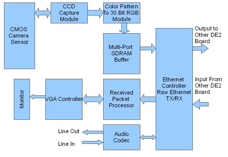
Figure 1. Proposed Hardware Configuration
Camera Module:
The hardware for the camera was provided by Terasic through their demonstration code.
CCDCAPTURE
The first module in the camera system is the CCDCAPTURE Module. This is the module that gets the raw data frames and pixels from the CMOS camera on the external board which is connected through the GPIO 1 On the DE2 Board. The CCD Capture module then sends the raw captured data to the RAW2RGB Module.
RAW2RGB
This is the second module in the camera system. It takes the raw camera pixel data and converts it into 30 bit Red, Green, and Blue Pixel Data. There are 10 bits for each color for each pixel in the frame. The Resolution of the camera image is 640x480 pixels. After converting to the 30 bit RGB, this module sends the data to the SDRAM Buffer.
SDRAM Buffer
The SDRAM buffer uses a custom interface designed by Terasic to take the pixel data and store it to an address relative to the defined pixel. It is a 4-port read/write simultaneous FIFO format. The VGA Controller can request pixel data at the same time the Pixel data is being written by the RAW2RGB module.
VGA Controller
In the example implementation, the VGA controller takes the RGB pixel data from the SDRAM FIFO and requests it pixel by pixel and displays the data on the corresponding monitor via the VGA port.
Possible Ethernet solutions
Hardware:
The Ethernet module was based on the Ethernet controller interface implemented by Adam Shapiro. This module includes a packet processor, a receive and transmit FIFO, and a controller. The packet processor is used for interpreting incoming packets and recovering the data from within the packet. The FIFO stored receive and transmit data and the controller issued commands to the Ethernet controller. Before this interface can be used, the transmit portion of the controller must be implemented. Once the transmit is complete the controller should be able to transmit at 100MHz.
Software interface:
This solution would use the sample code developed by Terasic for the dm9000a controller. This controller uses the NIOS as an interface to the hardware. The advantage to using this system would be that the hardware and software are already written and the interface to the controller would be easier to use than the hardware interface. However, since this controller relies on a NIOS, the speed of transmitting packets would be more restricted than that of the non-software based controller. Other projects teams reported speeds up to 1.2Mbps using a modified version of the Terasic code.
We initially decided to use the software interface because the code was easier to modify and adapt for use with our project. However, the speed was not adequate for our desired video transmission.
Custom Transmit State Machine:
The state machine in the top level DE2 file is used to send transmit packets to the Ethernet controller. When the state machine first executes the data, state, and counter variables are initialized to zero. The data variable is used to send data to the transmit FIFO and the counter is used to control the number of data bytes written to the FIFO. The FIFO write line is set to zero to prevent data from being written to the FIFO before valid data is present. If the transmit FIFO is full then the state machine cannot proceed to the next state until the FIFO has free space. If the FIFO is not full, then the packet is sent to the FIFO.
First the FIFO write line is set high to allow data to be written to the transmit FIFO, and then the size of the packet is inserted. This size represents the number of bytes in the data section of the packet. The bytes used by the address and length are accounted for in the controller. Next the six bytes of the MAC address are inserted 16 bits at a time. The next word that is inserted is the type of packet being sent. This word would have been used to differentiate between audio and video packets. Then the data is read using a counter to track the bytes that have been inserted into the FIFO. The last state is the end state that inserts a zero word to signal the end of a packet.
Ethernet Transmit:
The code for the Ethernet transmit driver routine was written by Adam Shapiro, but we debugged the code so that it would function with our project. There several errors that were identified and resolved by us and other students in the lab. The transmit routine follows the same pattern as the state machine implemented in the top level, but at a register transfer level for the hardware ethernet controller.
Data transfer:
Since the camera runs at 25MHz and the ethernet has a maximum speed of 100MHz, the video should be able to supply the VGA with real time or near real time images. If both boards are transmitting packets at the same frequency, then ethernet controller should be able to alternate between receiving and sending packets. The audio data will be sent at each sample of clock and will be sent in between the transmission of video packets. The transmission of audio may delay the delivery of video frames, but the delay should be minimal since the audio is sampled at 48Khz..
Results
Unexpected Issues
When we first began the development on the hardware Ethernet interface for the camera, we encountered numerous issues. Several of those were overcome by the code provided by Adam Shapiro for the Ethernet (DM9000A Controller) drivers. The main issue was that we were not able to transmit packets reliably. We spent a substantial amount of time debugging the Ethernet transmit and receive for larger and more complex packets, but in the end were not able to achieve the desired speed for video communication. We then made the decision to attempt the same concept as the video, but with audio in its place. We found this to be more practical with the remaining time after debugging the Ethernet, and were able to produce an audio transmitting/receiving Ethernet example for demo. We do think, however, that given more time for debugging several small Ethernet issues, that the transmitting of video could be accomplished.
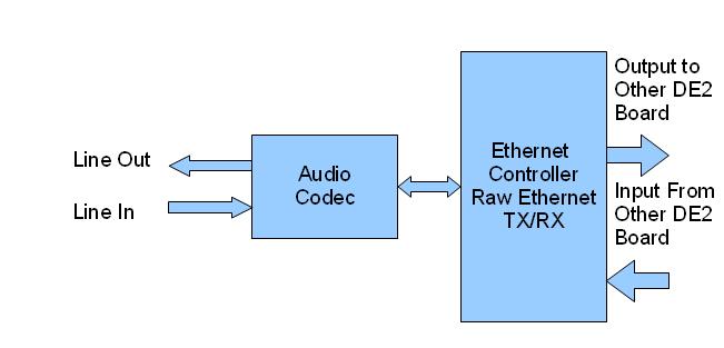
Figure 2. Actual Hardware implementation for Demo
Before the Ethernet controller was fully functioning, communication across the GPIO was considered as a safe alternative. Two DE2 boards would be able to communicate with each other if one of the GPIOs was used for the camera and the other port would send and receive video and audio. Our plan was to send and receive data on opposite clock cycles and audio data would be sent at every sample. A buffer would be used for the video data which could be delayed slightly whenever audio data needs to be sent. Since the audio data would have been sent at a frequency of 48kHz, the audio would be given priority over interrupting the video.
We were able to achieve a maximum ethernet transmit of about 48KHz, sending the minimum size of 60 byte packets. The actual maximum packet size was theoretically 1500 bytes of data per packet, not including the overheard. We were not able to transmit packets of this size, due to the bugs in the ethernet controller as discussed above.
Conclusion
When we began this project, we were not able to accurately predict the problems we would encounter. Due to these unforeseen issues, we were not able to produce a fully functional Video transmitting demo, we were only able to achieve the audio. In hindsight, there are several things that we could have done differently. First and foremost would have been to debug and attempt to test the Ethernet hardware much earlier. Had we done that, it would have been much closer to having the full results we were looking for. This project could also have benefited from video compression. Video transmission would be more effective if the data was more compact and took less Ethernet packets to transmit.
Our design takes several little parts from previously established designs. First of which is the Terasic CCD Camera demo hardware. This was the hardware that was used to capture and implement the small 1.3 megapixel CMOS camera. We were able to interface it somewhat with our custom hardware, but were not able to transmit the data over the Ethernet.
Another interface that we used was that of the Ethernet hardware provided by Adam Shapiro. He implemented both the transmit and receive protocols for the DM9000A Ethernet controller. Most of our time on that end was spent debugging and testing the provided hardware.
All in all, even though we did not achieve the most desirable outcome, we were able to learn a lot about the hardware interfaces at play here. We certainly have a lot more respect for the developers of Ethernet and its many complexities. Hopefully in the future someone can further refine our Ethernet hardware so that others may use it in future projects.
Appendix A: Verilog HDL Code
DE2_CCD Top Level - Includes our written state machine
DM9000A Controller - Written by Adam Shapiro - Debugged by Matt Kinne and Tim Sams
Packet Processor - Written by Adam Shapiro
Appendix B: Tasks
Ethernet Transmit Debugging – Tim
Audio Communication Optimization – Matt
Hardware Research – Tim and Matt
Nios II Software Testing and Integration – Tim and Matt
GPIO Debugging – Tim and Matt
References:
Adam Shapiro's Wiki DM9000A Documentation: http://gps.theengineersden.com/index.php/DM9000A
Davicom DM9000A Data sheet : http://www.davicom.com.tw/userfile/24247/DM9000A-DS-F01-101906.pdf
Davicom DM9000A Application Notes: http://www.dacomwest.de/pdf/dm9000a_application_note.pdf
ECE 5760 Website and Documentation by Bruce Land: http://instruct1.cit.cornell.edu/Courses/ece576/
Terasic Camera Reference Design: http://www.terasic.com.tw/attachment/archive/50/TRDB_DC2_UserGuide_061017.pdf