
Hardware/Software
Hardware
Video Capture
We used a Terasic 1.3 Mega Pixel Digital Camera Package to capture our video. This camera connects to the GPIO_1 expansion port on the DE2 board. Video frames captured by the camera were stored in an SDRAM buffer.
Face Detection
The face detection was performed on the FPGA. The specific algorithm we used was based on a paper published by S. Paschalakis and M. Bober at Mitsubishi. They proposed that only the red and green components of a pixel are required to determine whether that pixel could represent human skin. They defined two values L1 and L2 as the following:
L1 = L(G) + L(RGBmax)
L2 = L(R) – L(G) + L(RGBmax)
with the operator L(x) defined as
L(x) = log10(x+1) *106*2-15
and RGBmax equal to the maximum value that a single color component could take. In our implementation, we used 10 bits each for the red, green, and blue channels, so RGBmax = 1023.
In our design, we calculated the L1 and L2 values for each pixel in a video frame using a lookup table generated in MATLAB (see Appendix). If the L1 value was 128 or the L2 value was 100, then we labeled that pixel as skin and assigned that pixel to be white on our skin map. The values for L1 and L2 were determined by manually calibrating to our own skin in our lighting conditions in lab. From video frame to video frame, we found that even if the user was still, pixels in the background changed between meeting our skin color criteria and not meeting it, so we used an averaging module written by Professor Bruce Land (see Appendix) to remove these noise effects. This averaging module did a spatial average in the x direction. Our reasoning was that noise would be averaged away to darker shades of gray, while skin regions would still average to mostly white pixels. Next, we reduced the dimensions of our skin pixel map as suggested by Paschalakis and Bober. This was accomplished by first partitioning the 640x480 image into 16x16 blocks, each one corresponding to a single pixel on the 40x30 image. We set a threshold for the number of skin pixels in the 16x16 block required for the single pixel in the 40x30 image to be labeled as skin. We decreased the size of the image to reduce the effects of noise, and to average over details like glasses and moustaches that may not be skin tone. Finally, we calculated the centroid of the skin pixels on our 40x30 image and used it as the location of a face for a single frame.
Because each pixel on the 40x30 skin map represented a 16x16 block on the original 640x480 image, if the centroid only moved one block from frame to frame, it actually moved 16 pixels on the 640x480 VGA monitor. By modifying the Bresenham line drawing algorithm we determined the shortest path between the old centroid location and the new one. Whenever the centroid changed, we set the face location to travel along the shortest path between locations to smooth over these 16 pixel changes. The face’s offset from the center of the VGA screen was passed into the Nios II, along with the area of the skin region we calculated while determining the centroid.
VGA Display
The Nios II calculated the 8 corners of the projected cube to draw, and these corners were connected with 12 line segments in hardware using a Bresenham line drawing algorithm. These 12 line segments were stored in SRAM. By using SW[0], the VGA would switch between displaying the projected cube and displaying the skin pixel map with the centroid drawn as a red dot. The pixel map also showed a smaller green dot that represented the face’s location as it moved along the shortest path between changing centroid locations.
Software
We used a perspective projection algorithm that projects a point in 3D space onto a 2D surface based on the viewer’s location. In this algorithm, the following variables are used. Each variable is a 3x1 vector:
ax,y,z - the point in 3D space that is to be projected.
cx,y,z - the location of the camera.
θx,y,z - The rotation of the camera.
ex,y,z - the viewer's position relative to the display surface.
First, the vector c – a is found, and it is rotated using θ to give dx,y,z.
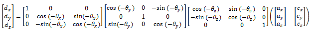
Finally, the projection, bx,y, is calculated:
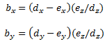
In our project, we defined a cube in 3D space, resulting in 8 different a vectors, one per corner. We defined the camera location as the origin so that a – c is simply equal to a. We defined the x and y components of e as the offsets from the user’s face to the center of the VGA screen in the x and y directions. We defined ez based on the size of the area of the skin region. The ez values added depth to our projections. To remove noise effects on the area input, we performed an integer division of the area by 20 before calculating ez. To remove the discrete steps in the z direction this introduced division introduced, we implemented a software version of Professor Land’s time averaging module.
The following picture shows the Nios II CPU we built:
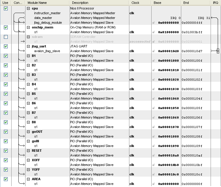
The B outputs each contain the x and y coordinate of one of the corners of the projected cube. XOFF and YOFF are used to input the x and y offset of the user's face from the center of the VGA screen's center. The AREA input is used for the area of the skin region determined when calculating the centroid. The goOUT and goIN PIO lines are used for flags between the FPGA and the Nios II.