Video: Program Demonstration
Abstract top
"Lattice gas automaton with mouse interaction in a DE1-SoC FPGA board"
Our program is a lattice gas automaton using the HPP model for the simulation of gases and liquids. We use FPGA to implement the lattice gas automation and use HPS to enable mouse interactions. With FPGA, the simulation speed will be much more faster; using HPS to handle mouse will avoid conflict on displaying the mouse cursor and the gas pixels.
High Level Design top
In this program, the fluid flow simulation mode that is used was the the first Lattice Boltzmann model. It was introduced by Hardy, Pomeau and de Pazzis in papers that were published in 1973 and 1976, so this model was also named HPP model. It is a 2-dimensional fluid particle interaction model. In HPP model, the lattice is square, and only move in four directions. This means the model is anisotropic, because it does not have much rotational invariance.More details will be provided in Program Design section.
We decided to implement the lattice gas automation in Verilog as opposed to the HPS in order to take advantage of the hardware to simulate as many nodes as possible (~2500) as fast as possible. We also decided to use the HPS for potential initial condition setup, mouse usage, cursor and text VGA display.
Program Design top
FPGA
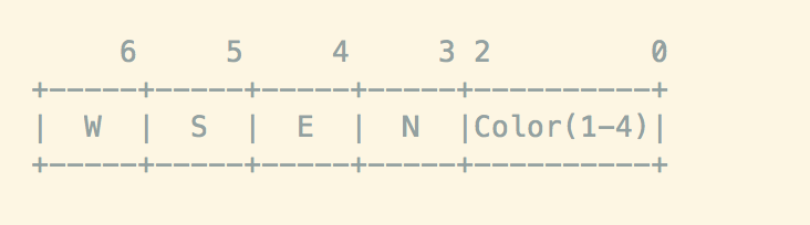
Fig.1 - Node 7-Bit Encoding
We model the square grid with a two-dimensional square array containing nodes. The color density is incremented when a particle occupies the node and each node can have a maximum of 4 particles (when there is a particle in each direction). If there is a particle going in the west direction, bit 7 will be set to high and likewise if there is a particle going in the east direction, bit 4 will be set to high. They are not mutually exclusive. We have a special color code for walls, with all three bits set to high (3’b111). Every iteration, we will check the three least significant bits to see if the node is a wall. If the node is a wall, we will update the wall accordingly.
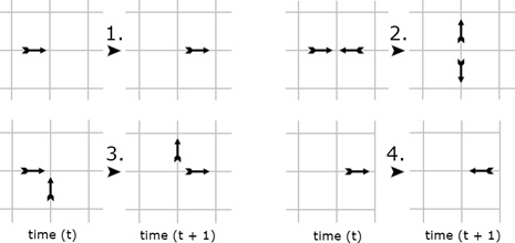
Fig.2 - Four Rules Governing the HPP Model (Source)
We create a node_update module that takes in the current node and its four surrounding nodes as inputs and then outputs an updated node. The following rules govern the model:
1. A single particle moves in a fixed direction until it experiences a collision.
2. Two particles experience a head-on collision are deflected perpendicularly.
3. Two particles experience a collision which isn’t head-on simply pass through each other and continue in the same direction.
4. When particles collide with the edges of a lattice, it rebounds.
The four rules are also shown in the figure above. There is a two-stage update process. We check and apply the four rules above if they satisfy the conditions, and then we move each particle one “square” step in the direction they are traveling.
VGA
The VGA bus master is responsible to write to the on-chip SRAM, which then provides data to be displayed on a monitor via the VGA port. We use a finite state machine to define the behavior of the bus master. When the FSM is reset, it sets initial values to registers such as bus write enable signal and x, y coordinates. Then the FSM begins with state 2, then alternates between state 2 and 1 in order to initialize the screen to be filled with black pixels. This is done to solve the problem when there is random data in the SRAM that causes the screen to display randomly. State 1 is responsible for finding when the bus acknowledgement signal is high, which indicates that another piece of data could be sent to the bus.
After the screen is initialized to be a black screen, we begin to alternate between state 0 and 1. State 0 calculates the x, y coordinates and pixel data to be displayed next. Since we actually simulate a 45x45 grid of gas particles, instead of displaying in a 45x45 area, we scale it up by 8 times, which would take up an area of 350x350 on the 640x480 monitor. We place the grid at the center of the screen.
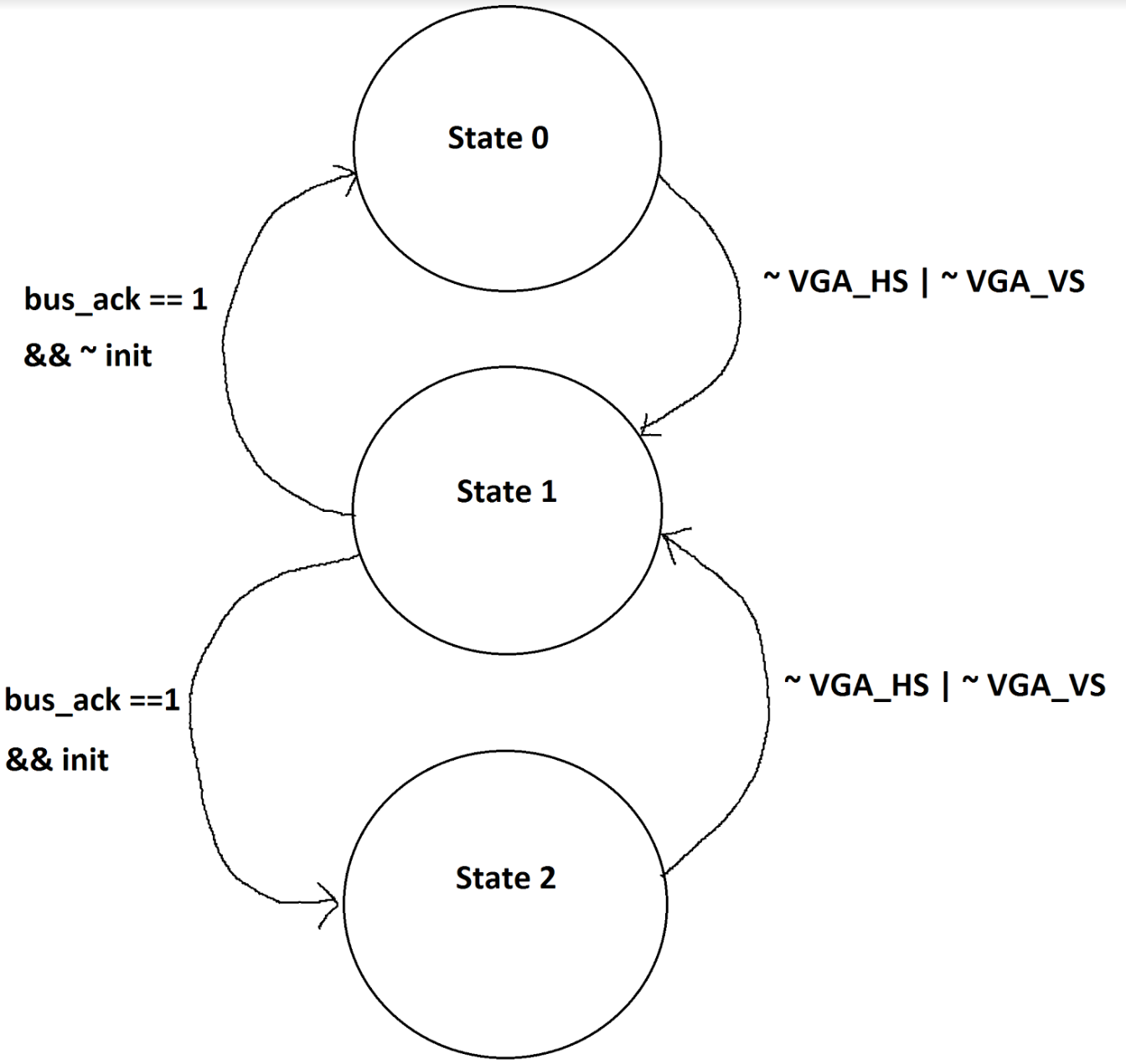
Fig.3 - Bus master FSM
HPS
HPS is used to control the mouse, and also updates pixels on the VGA display. The HPS program will draw the mouse cursor on the VGA display, and will also display texts on the VGA display. It overlaps the VGA updates from the FPGA, so there is no conflict between HPS and FPGA updates. This results in less lines of codes to execute and less registers to be used on the FPGA side. Thus, the FPGA will run faster, and able to handle more nodes.
The is a pio address wired up between FPGA and HPS. When a mouse button is clicked,the HPS will write data to the pio address. It is a 32-bit data. The most left significant bit was used to inform the FPGA to use the data. 0-9 bits are used to store the x-coordinate of the mouse, and 10-19 bits are used to store the y-coordinate of the mouse. With the mouse coordinates, once the left button on the mouse was clicked, the FPGA will change that pixel from free space to a wall.
There are still free bits, which can be used for future development.
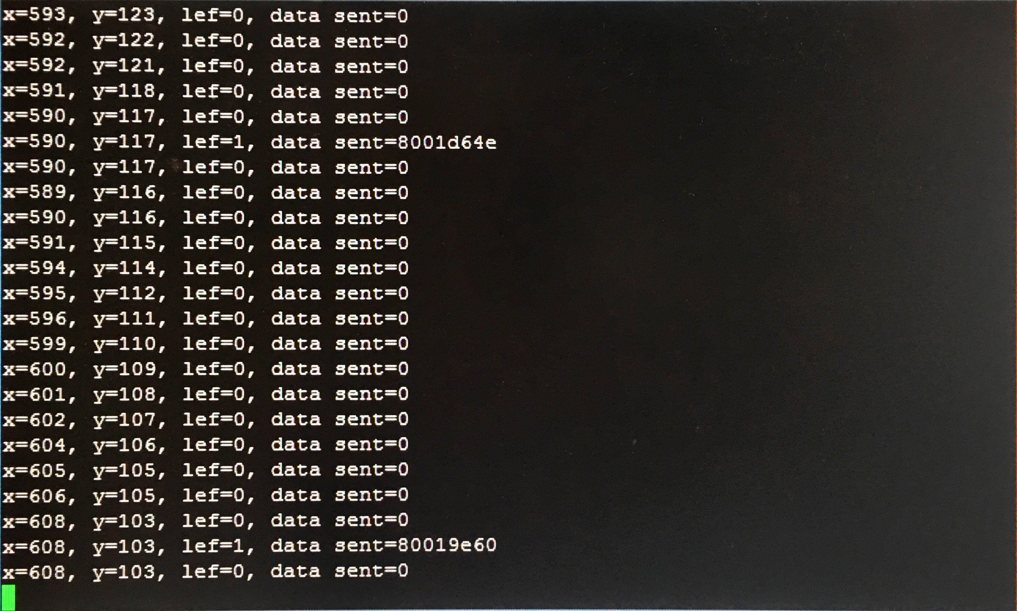
Fig.4 - Uart Output for the HPS
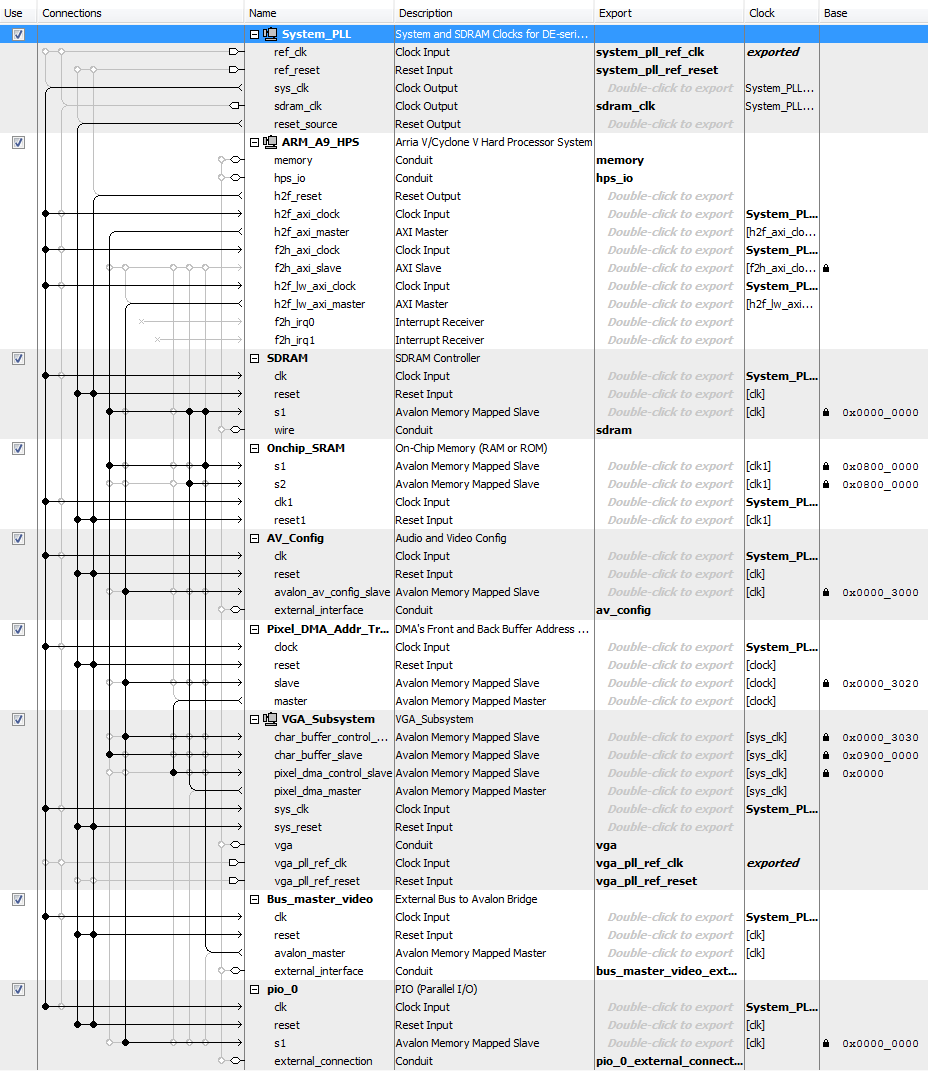
Fig.5 - Qsys Layout
Results top
We took an incremental design approach. We first created the node_update module and tested it in simulation with different surrounding node input. Once we confirmed the functionality of the node_update module, we created an outer module that instantiates the 2D node array grid. We started with a small 3x3 grid and gradually scaled it up to 45x45. Below are the following model-sim to test for the functionality of our code.
Two Cells Testing
We generated two cells, one moving from the left to the right, and the other one moves in the opposite. Here is the ModelSim simulation result:
Fig.6 - When two cells collide
Fig.7 - After two cells collide
From Fig.6 and Fig.7, we can see that when two cells collide, they will change their direction, rotate 90 degrees to its right.
Fig.8 - After one cell hit the wall
From Fig.8, we can see that when a cell hits the wall, it will change to the opposite direction.
Two Columns of Cells Testing
We generated two columns of cells, one moving from the left to the right, and the other one moves in the opposite. Here is the ModelSim simulation result:
Fig.9 - When a column of cells hits the wall
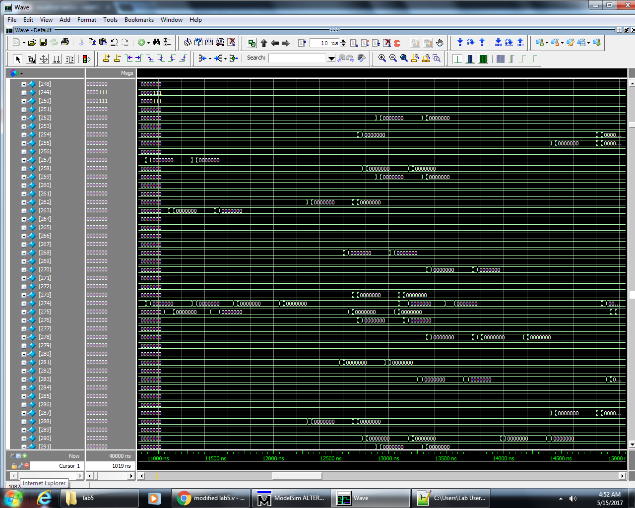
Fig.10 - After two columns of cells collide
From Fig.9 and Fig.10, we can see that in simulation, every pixel updates correctly with mutiple nodes.
Once we were confident with our simulation results, we start synthesizing our code onto the FPGA and attempt to get display onto the VGA. However, we had trouble getting the display correct. The particles on the display did not move in the way that we expected.
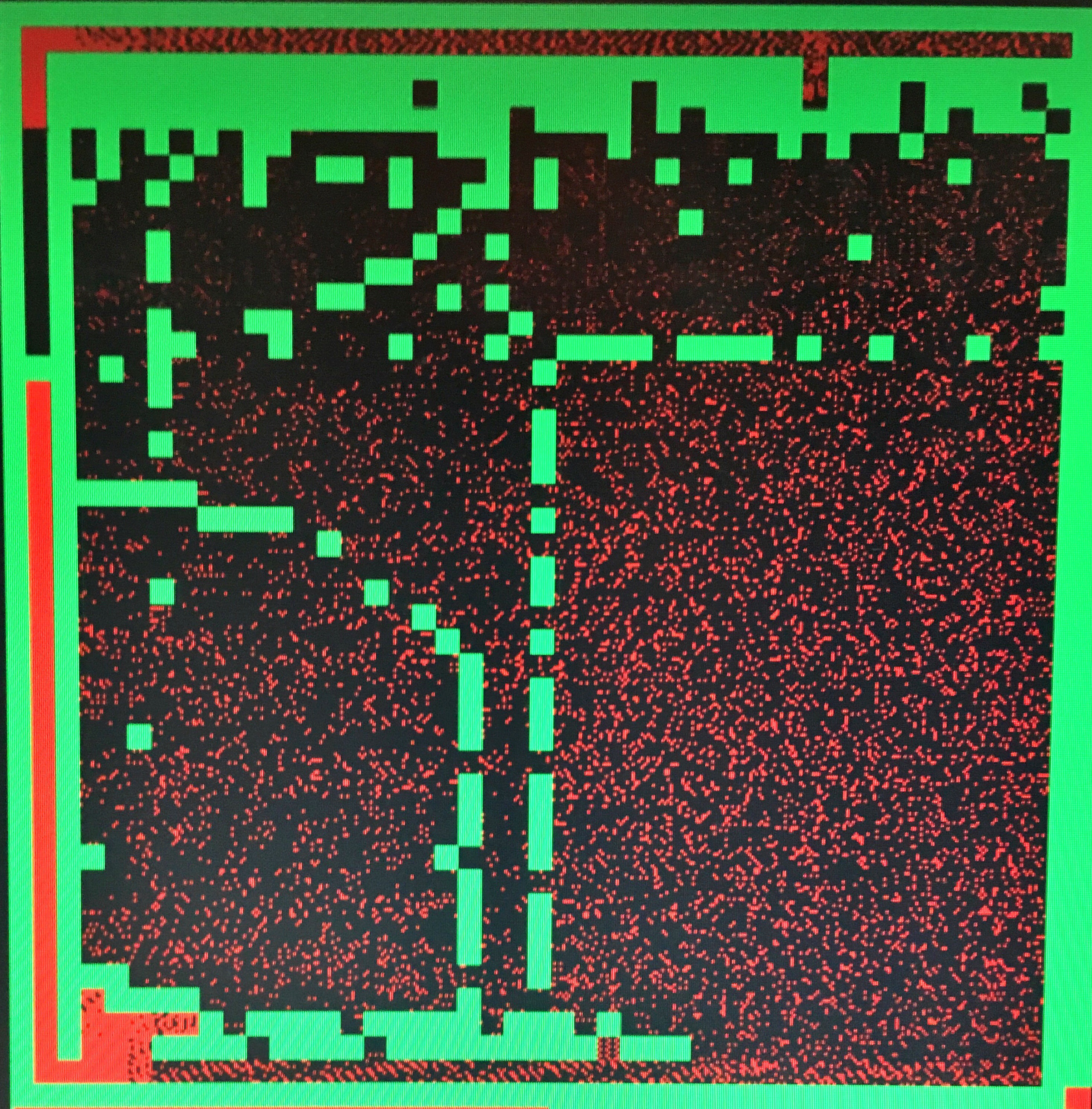
Fig.11 - Results for full program
In Fig.11 The Walls in the square frame are drawn by mouse. When cells hit those drawn wall, they will change their direction to the opposite. However, when we are drawing the walls, the new wall will "eat" some cells. The reason is because by the time we set those nodes to walls, the simulation of the cells is still running. If there are cells on the nodes that is being set to wall, those cells will be changed to walls.
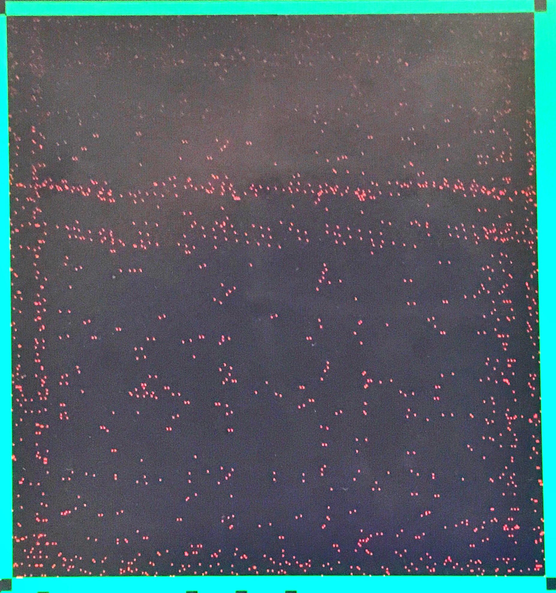
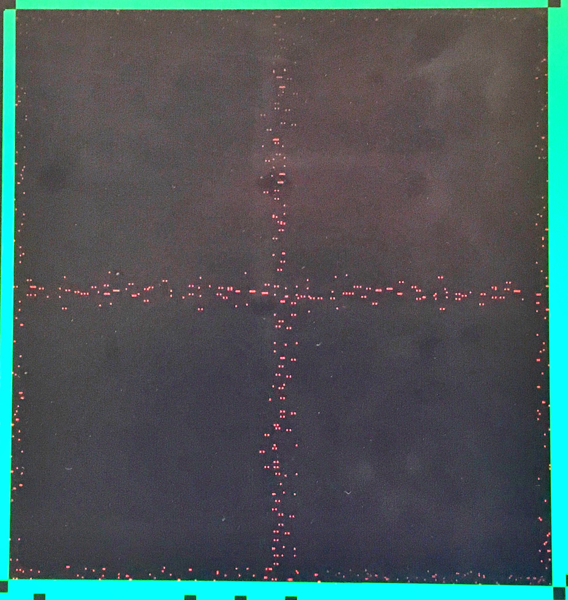
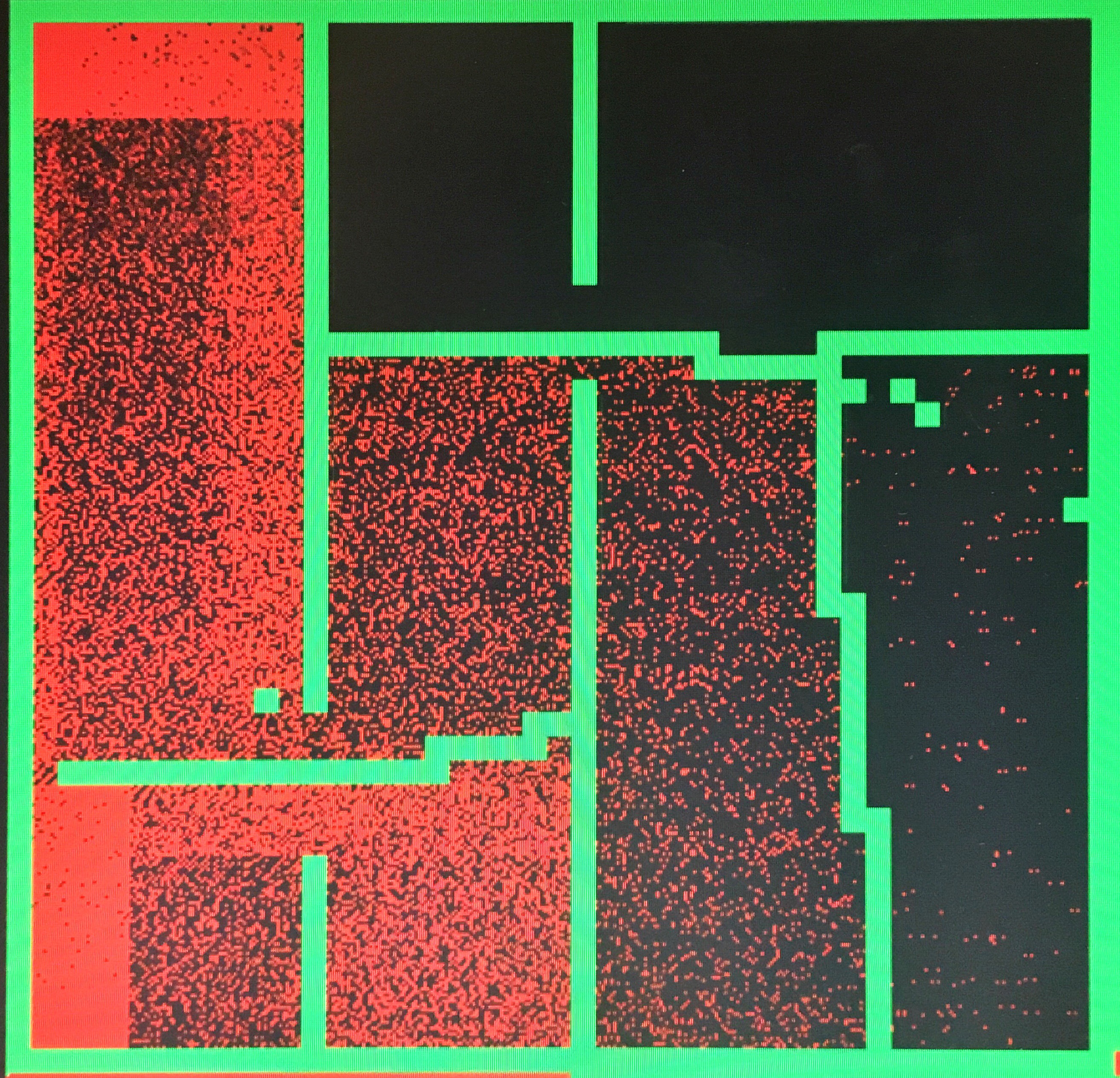
Fig.12 - Two Square Collide in the Middle of Screen(Left), Random Initial Condition (Right)
Fig.12 Left shows the result with an initial condition of two square collide with each other in the middle of the screen. Since HPP model is lack of rotational invariance, the result seems to be corret. Fig.12 Right has an relatively random initial condition, we can see that cells are everywhere, which matches what we are expecting.
Conclusions top
Our design is able to display particles on the monitor, and the particles were able to shift movement direction by 90 degrees after colliding with each other, also to bounce back after hitting the wall. However, our design somehow was not able to display the diffusion effect that gas particles gradually distribute evenly in a closed area. We worked hard to try to solve the problem, but unfortunately we ran out of time and did not fix it in time. We should have began with a simpler layout of walls and sources of particles that might help us realize the problem earlier. Also, we spent too much time to get the display working and it limited us from fixing the previous issue.
Intellectual Property Considerations
The result of our design is displayed onto a VGA screen with no wireless communication. As a result our design does not violate any applicable standard or legal restriction to our best knowledge.
Our HPP code was original and we followed the rules and outlines outlined from wikipedia. The bus master and HPS parts are modified from previous labs in the course. We used Altera’s parallel I/O port IP to enable the HPS to communicate with the FPGA and video IP core to get the VGA display.
This website was created by modifying the one created by Boling, Alberto, and Shaan for their ECE 4760 final project.
Appendices top
A. Program Listing
The group approves this report for inclusion on the course website.
The group approves the video for inclusion on the course youtube channel.
B. Program Listing
The source files for the program can be seen here. These files is not meant to be distributed and must be referenced when using all or portions of it.
C. Tasks
The work done for this project was evenly spread among team members. The contribution is even. Nathan focused more on nodes simulation. Boling focused more on HPS. Weier focused more on the VGA bus master. When there were difficulties, team members would group up to find out solutions.The contribution of all members was crucial for testing and optimizing the program.