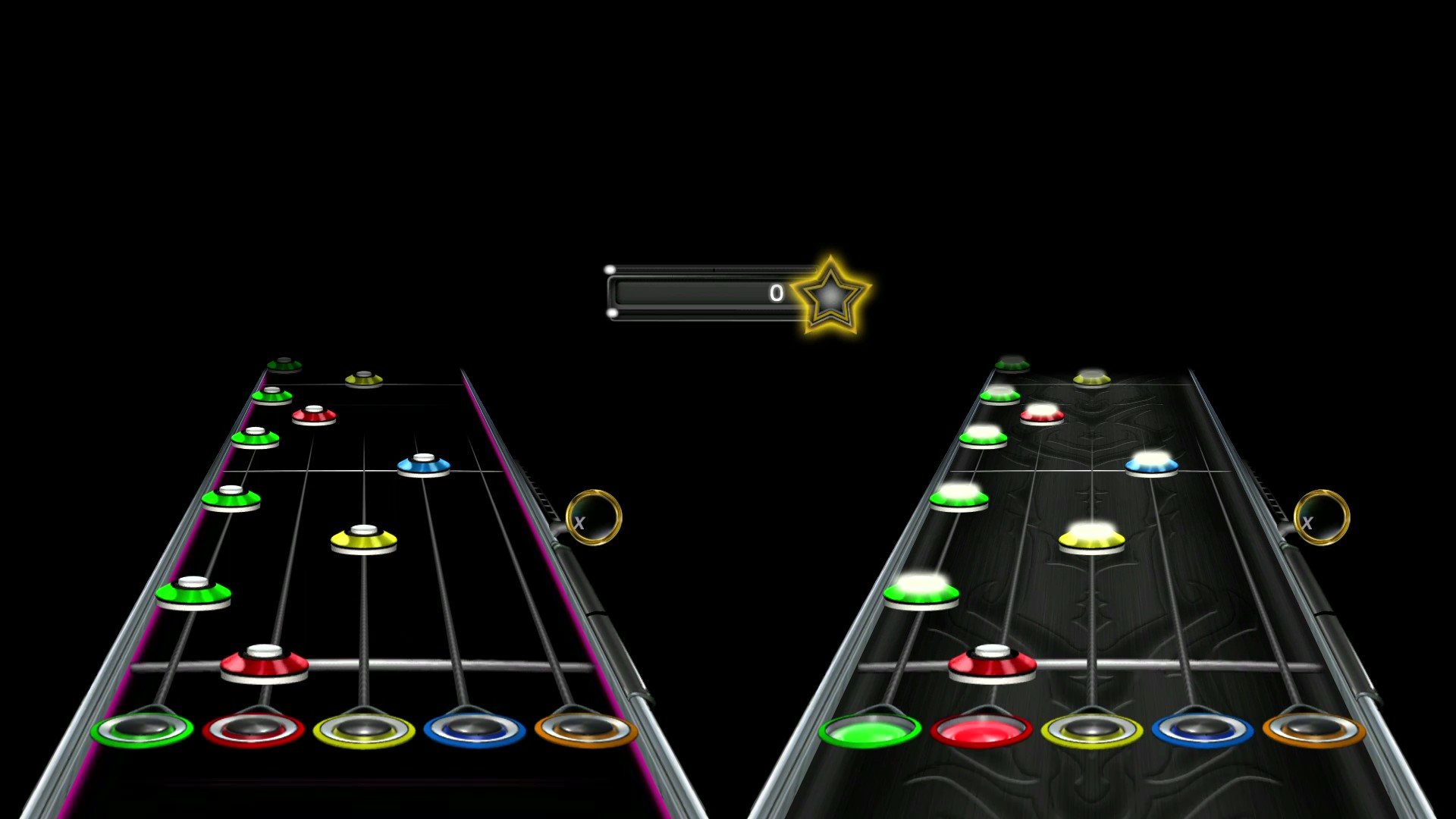
For our ECE 5760 final project, we created a system that would allow the DE1-SoC board to play the Clone Hero video game, which is a PC reboot of the popular game Guitar Hero. This game allows the user to play a “guitar” along with their favorite songs as accurately as possible to score the most points. The user-controller “guitar” consists of five keys: green, red, yellow, blue, and orange, as well as a bar with which to “strum” the note. While playing the game, colored notes descend toward the bottom of the screen and the user must strum at the correct time while pressing the corresponding notes. A few key qualifiers to this general rule is that there are some cases in which the game does not require you to play the exact notes coming down the chart highway. When playing single notes, only the note furthest to the right of the highway needs to be played to get the note, and the notes to the left of it are ignored (i.e. if they are pressed errantly it does not matter). This is intended to model a real guitar string, in which only the fret closest to where you are strumming dictates the note being played. This means that if there is an orange note, every color could be held down, and the note would still count, but if there was a green note, none of the other colors can be pressed when you strum. Outside of this scenario, all chords must be played precisely, with no errant colors pressed. Hitting only some of the notes in a chord also does not count.
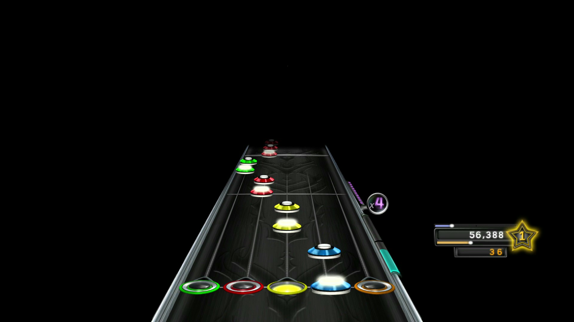
Figure 1. Clone Hero Song Track
The controller for this game is typically a plastic guitar with the buttons to press the notes and a bar to strum, located similarly to where they would be on a real guitar. Since Clone Hero is played on a PC, a keyboard can also be used to play the game, with different keys mapped to different buttons on the guitar.
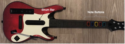
Figure 2. Clone Hero Guitar
A few different metrics can be used to determine how well a song is played. At the end of each song, a scoreboard is displayed indicating the score, the percentage of notes pressed correctly, the highest note streak, as well as some other metrics. To increase their score, a player must accurately play notes. If players correctly play multiple notes in a row, they will gain a multiplier. This will start by multiplying their score by 2, but will increase to 3 and 4 times as the player correctly plays more notes. If a player maintains a streak, their multiplier will remain at 4. Every time the player misses a note or plays a note when they shouldn’t (overstrums), the multiplier is reset to 1. Additionally, each song contains “star power phrases,” which consist of some number of star-shaped notes in a row. If the user correctly plays all the notes in the star power phrase, some of their star power bar is filled. Once the star power bar is filled, the user can choose to activate star power for a short time. While star power is on, the user’s multiplier is temporarily doubled, meaning that the user can have a maximum multiplier of 8.
Figure 3. Star Power
To play Clone Hero with the DE1-SoC, the board must be connected to the laptop running Clone Hero. The board receives the video input through the NTSC port. In this project, we used an HDMI to NTSC adapter which converted the HDMI output of the laptop into NTSC format. To press the keys, the board used optocouplers to interface with a USB keyboard plugged into the laptop through the GPIO pins.
Our project resulted in a design that can obtain an accuracy of over 97% on most songs. While this accuracy is typically not replicable by even the well above average player, hardware limitations and design choices leave some wiggle room in terms of beating the FPGA in actual song scores. The design also allows for one and two player modes, meaning the board can either play alone or play against a real user.
The goal of this project was to play the game of Guitar Hero as accurately and with as high of a score as possible. To do this, we needed to achieve three things: note detection, button scheduling, and button actuation, all in real time. The video input is 30 frames per second, therefore we needed to think critically about how to synchronize our hardware with the video input such that we would never miss frames. Aside from some minor challenges/hardware limitations, the high level design for this project was rather simple. We started by writing video input data into on-chip memory. This data would subsequently be read by a control FSM that fed this data into note detectors, which were looking for specific colors. When the colors were found, note detectors sent packets to a scheduler module which converted the packet into a number of cycles until the color was to be pressed. This cycle number was passed to the keyboard controller module, which was responsible for counting down the cycles, as well as pressing down a key for a given “press time” which we chose to be 20 milliseconds. Pressing the key, as far as the FPGA is concerned, was as easy as driving an output GPIO pin high. However, external to the FPGA, we needed to include a circuit with both resistors and optocouplers to act as a voltage-controlled switch for pressing a key on a keyboard. The optocoupler created a short whenever the GPIO pin went high. This was detected as a key press by the USB keyboard and sent to the Clone Hero game to hit the note.
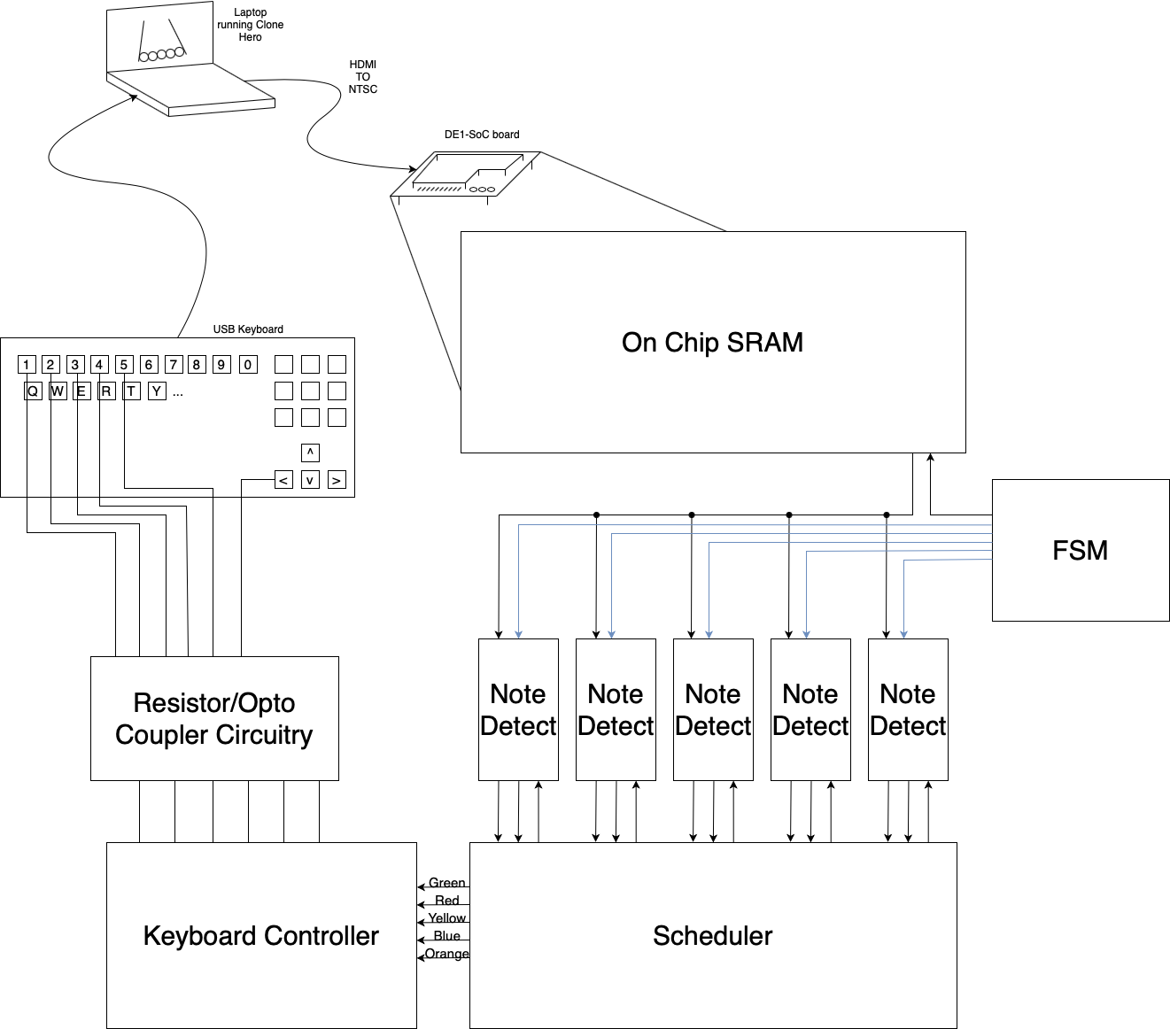
Figure 4. High Level Block Diagram of our Design
The hardware design fundamentally begins with the Qsys layout (see Appendix C). We begin by setting up the video-in subsystem to read the NTSC video into on-chip SRAM. We also configure 15 different PIO ports to allow for color detection adjustments, which will be described in greater detail below.
In order to facilitate straightforward design and debugging, we took a modular approach to coding the RTL for the project. The first module we wrote was the control FSM for the note detector module. The FSM handles setting the SRAM read address to access pixel data values. Additionally, it sets valid bits for each note detector to determine if the pixel data it receives is valid. The FSM is hardcoded to look in dedicated sections of memory for each color. This is because notes will always pass through the same section of memory, so it is enough to look at a small box in memory for each note. An important measurement we needed to consider was how high to make the box. In order to ensure that the same note was not detected more than once, we wanted the leading edge of a note to only show up in the box for one frame. Memory is updated at 30 FPS, meaning that each frame was replaced after 33 milliseconds. Thus, we needed to calculate how far each note moved down the screen in 33 milliseconds. To get this data, we took a frame-by-frame video of a song playing and measured the height difference between the note’s leading edge in back-to-back frames. On a 1080p laptop screen, this number was about 40 pixels. This corresponds to 10 pixels on the 320p video input we received on the FPGA, so we decided to make our box height 10 pixels.
![]()
Figure 6. Calculation of Box Height
The FSM is parameterized by the number of pixels in the box width, as well as the box height. Since we know exactly where the box begins in memory for each color, we used a lookup table to formulate the SRAM read address for each color’s starting pixel. We begin by starting at the top left corner of the box and then loop through the rest of the row, sending a number of read addresses equal to the number of pixels in the box width. Once an entire row of pixels is looped through, the FSM begins requesting the next row of pixels in the same manner. After each row in the box is read, the FSM jumps to the top left corner of the next box. Only one read address can be sent to the SRAM from the FPGA at a time, so the FSM reads all the memory locations for one box, then moves on to the next box. We designed the FSM so that it begins with the green box, then moves in order through the colors, so red, yellow, blue, and finally orange.
The FSM does not take the pixel data values that are outputted from memory as an input, but it does output valid bits to each of the note detectors. For example, if the FSM sets the read address for the first pixel in the green box, it must also tell the green note detector that the data it receives next cycle is valid. Since the SRAM has one cycle read latency, the valid signals must be carefully managed to make sure each note detector sees the valid bits when the correct data is outputted from memory. We handle this with 4 states in the FSM. The first state sets the read address for the top left corner in the green box, but does not send a valid bit to the green note detector. In the second state, we set read addresses and send valid bits to the correct note detector each cycle. We stay in this state until the cycle after we read the last pixel in the orange box. In the next state, we do not set a read address but do send a final valid bit to ensure the orange note detector receives its last pixel. Finally, we transition to the fourth state, which is the DONE state. Here, we do not send any valid bits and do not care about the read address sent to the SRAM. We stay in this state until the FSM is reset.
We used the NTSC TD_VS signal to synchronize the frame update and the FSM reset. The TD_VS signal goes to 1 at the start of every frame update, and goes to 0 halfway through the signal period. Thus, it has a period of 33 milliseconds and a duty cycle of 50%. We used the negedge of the signal as the FSM reset, because we needed to wait until all the memory was updated before we started reading data from it. In order to detect positive and negative edges of the TD_VS signal, we implemented a hardware synchronizer. The synchronizer is a 3-bit shift register that samples TD_VS every cycle. A negative edge is detected if the third bit of the shift register is 1 and the second bit is 0. A posedge is detected if the third bit is 0 and the second bit is 1.
The next module that we built is the note detector. The note detector module is the most complex module in our design, and required a significant amount of tweaking and data collection to get it right. The basic idea for the note detection scheme was to look at a rectangular box that was slightly less wide than a note itself (15 pixels) and was as tall as a note travels in one frame. The motivation behind this specific “box height” is to guarantee that the note detectors will only see the edge of a note once. This parameter is incredibly important, because if we make it too small, we will miss some notes, but if we make it too large, notes will be detected twice, and overstrums could occur.
In Clone Hero, the highway speed of notes is adjustable, with faster highway speeds resulting in notes traveling down the highway faster but also spaced further apart. The advantage of faster highway speeds is that we can support a faster maximum strum speed. This is due to the fact that at faster highway speeds there is greater separation between each note, meaning faster notes are less likely to overlap and not be detected. However, faster highway speeds also result in both a larger required box height and less time between note detection and keyboard actuation. We found that a highway speed of 10 (default is 7) worked best in practice.
Once we had acquired the correct box dimensions as described earlier, we needed to pinpoint where these boxes were located. To accomplish this, we utilized the VGA to draw a small box of the video input, and overlay our anticipated box locations to verify they were in the correct location. The details of how we drove the VGA are covered in more detail in the software section.
Video 1. Boxes drawn on VGA screen with notes passing through them
We proposed a simple algorithm to detect notes and provide this information to the scheduler module in the appropriate format. The data format of the video that was provided in on-chip SRAM is an 8-bit value, of which the three highest order bits correspond to red, the second set of three bits are for green, and the final two bits are for blue. Each time the FSM indicated to a note detector that its pixel data was valid, the note detector added the R, G, and B components of the data to three distinct accumulator registers. These accumulators kept track of how much red, green, and blue the note detector found in a given row. Given that there are three bits to represent red and green, 7*15=105 is the maximum amount of red or green that we can have in a particular row. For blue, two bits indicates that 3*15=45 is the maximum amount of blue that we can have in a given row. Once we get to the end of a row, we evaluate the accumulator registers to see if they satisfy the color constraints passed to this note detector from the software. If so, we update registers indicating that we detected a note, and we also indicate the row in which we detected it. Then, we reset the accumulators and move down to the next row. If we find that the following row also satisfies the color threshold requirements, then we update the row in which we found the note. In the figure below, we showcase how the note detector for a red note would handle the given input.
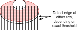
Figure 7. Note Detection Diagram
We choose to detect the lowest possible edge and send that to the scheduler, so that we are as consistent as possible in the timing that notes are played. Given that we determined a note travels roughly 10 pixels per frame, each pixel row that we are off by corresponds to roughly a 3.3 millisecond change in schedule time. We determined that being inconsistent by a margin of about 3 pixels would be consistent enough for the game to be playable, since the human ear only starts to discern that music isn’t in time with the game if the calibration is off by about 15-20 ms. When the entire box has been processed, the note detector tells the scheduler that its data is valid. The payload we sent to the scheduler consists of a press signal, and an edge height. When the scheduler is ready for our request, the valid bit will be reset the next cycle in the note detector.
The scheduler tells the note detectors that it is ready for a request every 33 milliseconds. This is handled by setting the ready signal on the positive edge of TD_VS. This ensures that note presses are scheduled at 30 FPS and that the whole design will be synchronized with frame updates from the NTSC input. When the posedge is detected, the scheduler looks at each of the valid press bits from the note detectors. If a detector says there is a valid press, then the scheduler will look at the edge height it received as well. The scheduler’s job is to translate the detected edge height into the number of cycles until the note should be pressed and strummed. Essentially, it calculates the number of cycles until the note will reach the bottom of the screen. This is done by multiplying the number of cycles that it takes for a note to move one pixel by the pixel edge height. Finally, a box offset parameter is added that accounts for the number of cycles it takes to hit the note from the bottom of the box. The scheduler then packages the press valid bit and the number of cycles until the note should be pressed into a struct and sends that data to the keyboard controller module.
The keyboard controller takes packets from the scheduler and when they are valid, enqueues them into a “countdown queue”. This queue decrements every entry in the queue each cycle to count down the number of cycles until the note should be pressed. Once the number of cycles reaches 0, it is time to dequeue the packet and to press the associated note. The controller “presses” the note and “strums” by setting the associated GPIO pins to 1 for a number of cycles dictated by some press time. Both the notes and the strum bar have a dedicated GPIO pin, so there are 6 in total. These GPIO signals are used to control the USB keyboard as detailed in the External Hardware section.
In the top-level RTL module, we instantiated our bot and hooked up the PIO ports, switches, LEDs, and GPIOs. In addition to the GPIO pins, we also connected the note presses to LEDs, allowing us to visually confirm that the FPGA was detecting and pressing notes. We used this to isolate problems when a note was missed. We attached switch 0 to the TD_RESET signal, so frames would only be updated when the switch was on. This was helpful if we wanted to freeze the video so that we could see how the FPGA behaved for a specific image. Switch 1 was attached to the player mode. This allowed us to minimize our recompiles, as the FPGA could play alone or with another person just by flipping the switch. Switches 8 through 2 were tied to the box offset. We tied this to the switches so that we could dynamically calibrate the detection-to-strum timing without recompiling the hardware.
Video 2. Cliffs of Dover with LEDs Flashing (FPGA is on the left side)
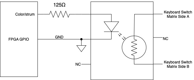
Although our FPGA is able to set GPIO pins to simulate button presses, we needed a way to have the USB keyboard detect that its keys were pressed. Thus, we designed a circuit that translated GPIO signals into key presses. For each note, we used an optocoupler as a voltage-controlled switch. The optocoupler has an internal LED and a photoresistor. We connect the terminals of the LED to ground and the GPIO pin. We also include a current-limiting resistor to decrease the voltage across the diode to 1.3 V. From the optocoupler datasheet, at 1.3 V the diode draws 16 mA. The logic level of the GPIO is 3.3V. Thus, we needed to drop 2 V over the resistor at 16 mA. From Ohm’s Law, R=VI=2.016=125. We then connect the two terminals of the photoresistor to the two matrix sheets of our keyboard. When the GPIO output is set to 1, current flows through the LED and turns it on. The light from the LED decreases the resistance of the photoresistor. The keyboard we used contains two sheets that together form a switch matrix in which we can conventionally record a press by pressing the pads from the two sheets together, creating a short. Once the LED turns on, the resistance of the photoresistor is low enough that the keyboard detects a short and presses the associated key. The USB keyboard is plugged into the laptop that Clone Hero is running on, so its key presses directly hit notes in-game.
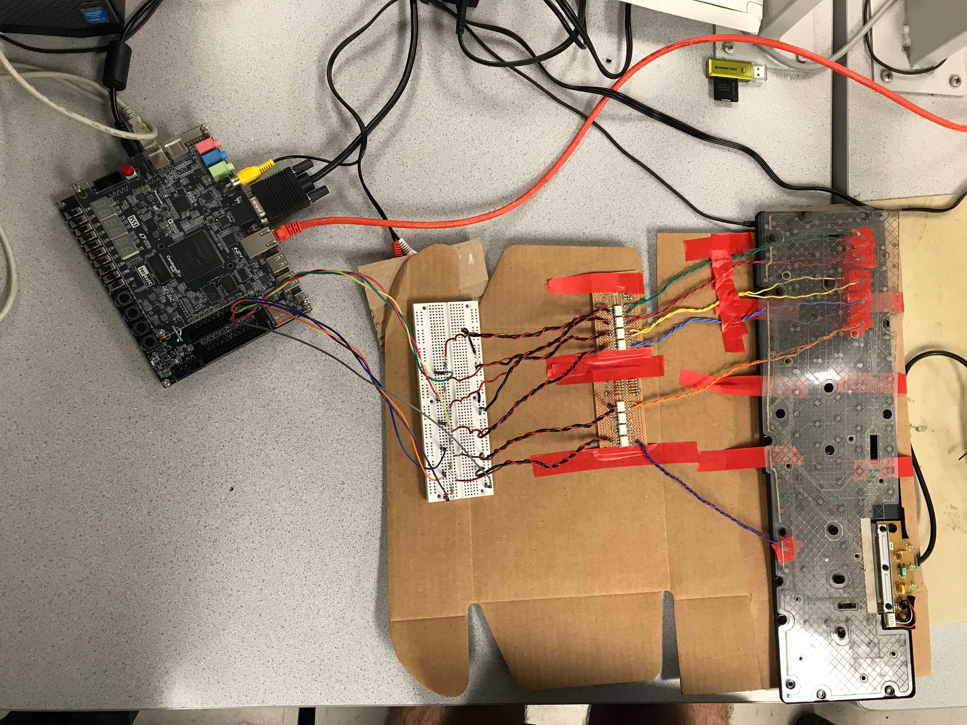
Figure 8. External Circuit to Actuate the Keyboard
The software for this project consists of a C program running on the HPS that moves the on-chip memory written to by the NTSC into two other memories. As with all peripherals interfacing with the HPS, this is done by reading to and writing from specified memory locations in C. The program begins by reading the on-chip SRAM written to by NTSC. It then writes this value to the SDRAM used by the VGA as well as another on-chip SRAM used by the FPGA. In addition to copying the NTSC data to the VGA memory, the program also draws boxes on the screen that show in which sections of the screen the FPGA is looking for notes. While the copying of data into the VGA memory is not necessary for the design to function, viewing the same data as seen by the FPGA is a useful debugging tool to ensure correct video input is being received. Since reading the entire NTSC display introduces additional latency in the design, only the small portion of the screen containing the notes is copied. To ensure the correct sections of the screen are copied in both one and two player modes, the program begins by asking the user in which mode the game is being played.
In order to speed up the process of determining which color thresholds should be used for checking each note, the thresholds were tied to PIO ports. This allows the thresholds for each of the five colors to be changed in C without having to recompile the Verilog each time they are changed.
We used the PyMTL3 framework in order to verify the Verilog modules that we wrote. PyMTL3 is an open-source Python-based hardware verification framework that is used in the ECE 4750 and ECE 5745 courses, as well as in Professor Christopher Batten’s research group at Cornell University. To test Verilog within PyMTL3, the Verilog module is contained inside a PyMTL3 wrapper. This wrapper connects to the Verilog module’s ports and transitions to the Python-domain. Then, the PyMTL3 wrapper is instantiated within a Python test harness and input stimuli can be applied to the module’s ports. Python syntax is accessible and simple to write, so writing tests in Python enables quick verification bringup. Additionally, it is easy to write random tests in Python, so we can run thousands of tests on our Verilog module to catch any potential bugs.
We used an incremental testing approach in this lab, aggressively unit-testing each Verilog module before integrating with other components. To simplify the creation of different tests for each module, we built a method-based test harness for each module. For the countdown queue used in the keyboard controller, the test harness included methods to enqueue a value indicating the number of cycles to countdown, a method to tick one cycle of the simulation, and a method to check when the countdown was done. We used this harness to quickly create multiple tests to ensure the queue behaved correctly during normal operation, as well as with edge cases such as when the queue was empty or full.
The keyboard controller module that contained the countdown queues for each of the five colors had similar methods. In order to write and check multiple colors at a time, the methods to enqueue and check the queue outputs took a mask which indicated for which colors a value should be enqueued and which countdowns should be finished in a certain cycle. The use of a mask allowed us to ensure correct behavior when multiple notes are played at the same time.
The note detector test harness included methods to simulate the reading of memory into the note detector. The tests for this module involved creating an image of a note and sending it pixel by pixel into the note detector. Once the entire image was loaded in, we could check both if a note was detected and at what row of the image it was detected. Test cases for this module included checking if a note was detected or not based on the given threshold values, as well as ensuring the note was detected at the correct height of the image.
The scheduler module tests had to check if the outputted number of cycles was correct for a given edge height. This was done by calculating the expected number of cycles for a given edge height in Python, then comparing the result with the output of the scheduler module. A similar strategy was used to test the module containing the FSM. In this case, a functional model was created in Python to determine which memory address should be sent each cycle and what color it corresponded to. The output of the functional model was compared to the FSM module each cycle to ensure correct behavior.
Once the RTL was unit tested, we were able to integrate the design and load it onto the FPGA. Although integration testing is typically first done in simulation, we decided it would be simpler to test on the board through the use of real video input. Since the external hardware had not been created yet, we tested the output of the design through the FPGA hex displays and LEDs. Each of the five colors, as well as strum, were mapped to a hex display and an LED which would flash whenever that color was pressed. This method allowed us to see what colors the design was seeing as well as when it thought the colors should be pressed and strummed.
Once the hardware was configured and we could begin testing the system on the real clone hero game, we quickly noticed a few unanticipated issues. One problem we encountered was that the countdown queues tracking how long until a note was played would occasionally lock up, preventing any other notes from being played. After observing the behavior and reviewing our code, we identified the problem as a result of underflow in the countdown queues. At the time, we had been pressing notes too late, due to unexpected hardware latency introduced by the GPIO-optocoupler and keyboard USB interface to the laptop. To remedy this, we tried enabling a negative box offset parameter that would subtract from the scheduler’s anticipated number of cycles. This resulted in underflow, allowing extremely high cycle counts to be passed to the countdown queues. As a result, the queues would wait nearly a minute and a half to play a note, locking up the queue. Another assumption we made when designing the queue is that each note would only appear in one frame, and as a result, would only be scheduled once. Since the exact note speed and detection window were difficult to calibrate, our design introduced the (rare) possibility of the same note being detected, and scheduled, more than once. Since the queue assumed each note could only be scheduled once, it would only check the single oldest entry to determine if it was finished and decrement the rest of the entries. In the case that two notes were scheduled for the same time, when the countdown hit 0 one entry would be dequeued and the other would be decremented, resulting in underflow and a seemingly very long time until the next note should be played. For this rare case, we allow both entries to be dequeued if they are scheduled for the same cycle, effectively collapsing a double detection back into one event.
Another problem we immediately discovered was that the board would often have false positive note detections. Our preliminary note detection scheme looked at a thin white line at the bottom of every note to determine if a note was present and where it was on the screen. The logic behind this method was that using the thin white bar would provide the best estimate of where the note was on the screen, and by extension, how long until it should be played. A problem we later realized was that white lines also appear on the highway at every downbeat. These white lines would appear to be notes to the note detectors, resulting in the board playing notes on every downbeat regardless of whether any were present. After attempting to remedy this problem by changing the threshold of white, we opted to change our note detection scheme to search for a given color range for each note instead of just white. Although we were worried about the potential loss of timing accuracy, this was resolved by searching from the top of the screen to the bottom in order to find the lowest bar of color signifying the bottom of the note.
To switch over to color detection instead of white detection, we needed to provide each note detector with 6 parameters controlling the acceptable ranges (min and max) for the three accumulators for red, green and blue. For each note color, we determined whether or not we wanted to detect a certain color (i.e for green we want to detect green, but not red or blue). In the case for green, we would then hardcode the maximum acceptable range for green to be the maximum value of 105 discussed in the hardware section, and we would also hardcode the acceptable minimum value of red and blue to be zero. Thus, for each note detector we only needed three PIO ports to specify a desired color to detect, one for R, G, and B respectively.
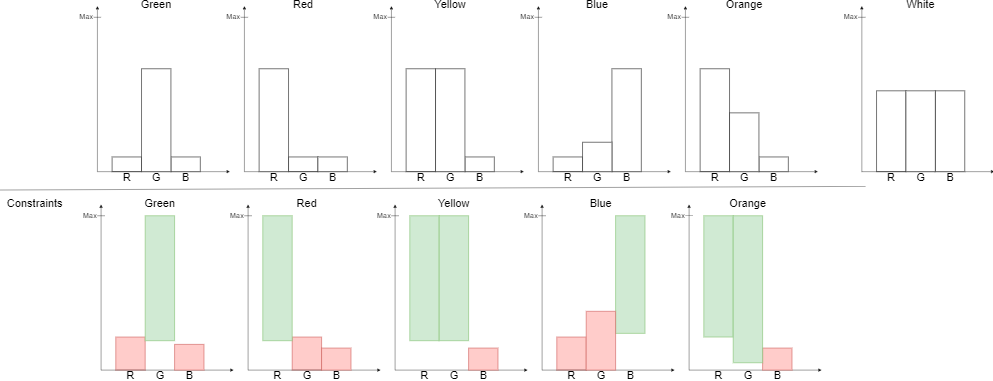
Figure 9. Thresholds used to detect different colored notes
In the image above, the top row specifies the color profiles we were trying to detect with each note detector, as well as the off-white color profile we were trying to reject, in the top right. Take green for example. In order to detect the green consistently, we make the minimum threshold for green rather small, but large enough so we do not detect when there are no notes in sight. The important part in rejecting the white bars is the maximum thresholds we set for red and blue. White contains all colors, so if we see white we will not detect it because it will exceed the allowable threshold for blue and red. We apply this principle for all 5 colors, noting that orange and blue are not purely on or off in terms of RGB components. The shade of blue we were trying to detect actually contained a bit of green in it, so we needed to raise the maximum amount of green allowed to detect blue, and needed to count on the maximum threshold for red to reject white.
Once we applied the proper thresholds as shown in the bottom row of the image above, our errant note detection was reduced significantly. We no longer saw errant strums on downbeats when no notes were present. This greatly increased our capacity for obtaining streaks, which improved overall score performance as well as note hit percentage.
The final calibration features we needed to tune were the box height as well as the highway speed and the box offset parameter. Recall that the box offset is the extra number of cycles that we would need to add to a note that was detected at the bottom of the box. In our original design, we noticed that notes were being pressed incredibly late. We realized that this was a result of external hardware latency taking roughly 30 milliseconds to actuate the keyboard from the time that GPIO pin was pulled high. In order to remedy this, we needed to move our video input boxes vertically higher in order to give us more time to actuate the keyboard. We had slowed down our highway speed from 10 (what we designed our system for) to 7, to try to accommodate for the delay in keyboard button presses before elevating our boxes. When we moved our boxes higher, we played a difficult song three times with increasing note speeds to see which performed the best. We noticed that at note speed 10, and a box offset of 0 cycles, we actually perfectly time note presses, and achieved the best result in terms of accuracy and score. As a result, we decided to go forward with note speed 10 and the full results of that experiment are shown below:
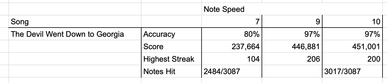
Figure 10. A comparison of board performance for different note speeds
Video 3. FPGA Hitting Cliffs of Dover Sequence (FPGA is on the left side)
Our bot was ultimately capable of playing Clone Hero with an average note accuracy of over 97%. The design is also extremely consistent across playthroughs, meaning it hits/misses almost exactly the same notes each time it plays a song. In order to characterize our design, we chose a set of songs of various technical difficulty and chart type. For example, we choose some songs with lots of single notes, some with lots of chords, and some with lots of extended, or sustained, notes. All songs were played in Expert Mode but even still, some songs are inherently far easier than others. In order to put into perspective how hard a song is for a human to play, all three members of our team played against the FPGA to contextualize the FPGA’s performance. We create three bar plots, one for the Note Accuracy, one for the Song Score, and one for the Maximum Note Streak, split by song.
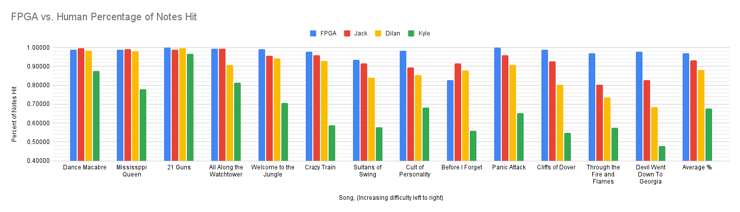
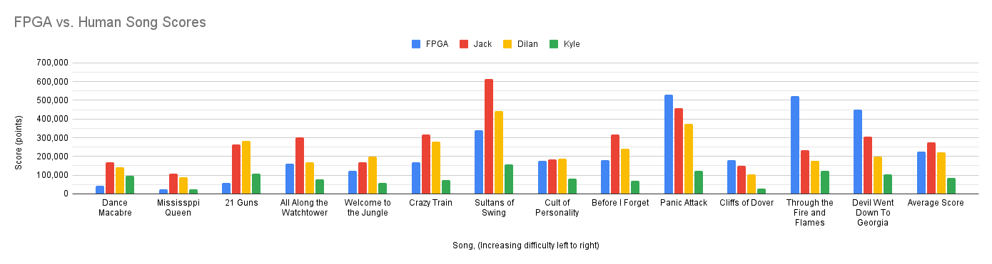
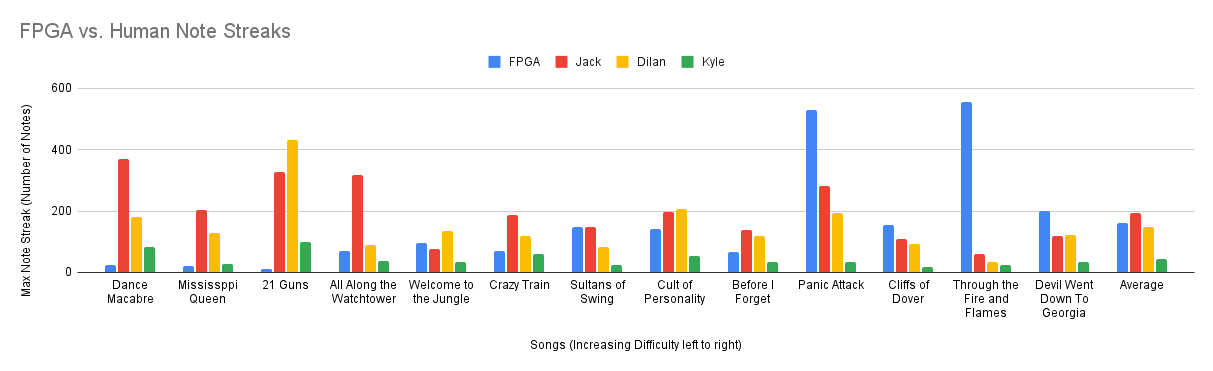
Figure 11. Accuracy, score, and highest streak graphs for the board and group members for different songs
As can be seen from the plots, the DE1-SoC is able to perform at a consistently high level percentage wise, even on difficult songs such as “Through the Fire and Flames'' and “The Devil Went Down to Georgia.” These songs are considered harder because the speed and arrangement of the notes make it difficult for a human to play. However, since the reaction speed of the board is on the order of microseconds, the speed of the chart does not inherently affect its accuracy, up to a point. The only case when the board might miss notes as a result of track speed is if the notes are overlapping on the chart. In this case, the board would only perceive one note when there are actually two. Difficulty as a result of finger orientation is also irrelevant to the board for obvious reasons.
Video 4. FPGA missing a few notes in a fast solo because notes overlap
One limitation of the board is that it double strums on sustained notes. Since the tail of a sustained note is a more pure color, the color is enough to meet the threshold of detecting a note. As a result, the note detector believes there is another note, resulting in the board strumming a second time. While this does not impact the accuracy as a percentage, it does break any streaks the board may have. This can prevent it from accumulating a large score multiplier compared to a human. Although it may seem easy to simply increase the minimum thresholds for colors we do want to detect, we found that this would result in missing some notes entirely, and therefore as a tradeoff we decided to sacrifice the ability to maintain streaks on sustains in order to support greater consistency and note accuracy. Another limitation is that the board is unable to activate star power. Upon activating star power, a user’s current multiplier is further multiplied by 2 and all the notes temporarily change color to a light blue. Since the note detectors use color to identify notes, this causes them to miss every note until the star power ends. In order to prevent this, the board never activates its star power. These two limitations are largely responsible for results such as “Crazy Train,” “Sultans of Swing,” and “Welcome to the Jungle,” where Jack and Dilan had lower accuracy than the board, but still obtained a higher score.
Another limitation of the design is a result of the USB keyboard used by the board to interface with the computer. One restriction of this keyboard is that only certain combinations of keys can be pressed at a time. Although the USB keyboard protocol allows for up to 6 keys to be pressed at once, some combinations are simply unsupported. As a result, the board is physically unable to hold some three note chords while also strumming. We were able to confirm this restriction through the use of the LED’s, with which we could see the correct chords being played. The effect of this can be seen in songs such as “Before I Forget” which contains many of these unplayable chords.
Video 5. FPGA missing chords unplayable by the keyboard
Despite these limitations, we are extremely pleased with the result of this project and the performance the design is able to achieve. The performance of the board is also not impacted by changing between one and two player modes, allowing for a human to play against the board. Since the board acts only as an additional player from the perspective of the game, the user experience while playing the game is not affected in any way by the board. Although the current limitations of the design are not ideal, they do make the competition between the board and a human much more achievable.
Video 6. Whole Hardware Setup with FPGA playing Panic Attack against Dilan (FPGA is on the left side)
This design exceeded our initial expectations in terms of both accuracy and consistency. With the exception of a few songs containing many chords unplayable with the current hardware, the board was able to achieve accuracy in the mid to high 90 percent range. The largest limitation of the current design is the overstrumming that occurs during sustained notes. It would likely be possible to remove this overstrumming by changing the section of each note viewed by the note detectors. Since the sustained note is represented by a thin bar in the center of the note, this problem could potentially be avoided by only checking the sections of the screen on the left and right side of each note. However, this would reduce the amount of color that could be seen by the note detector, and as a result, may decrease the overall note detection accuracy.
Another possible improvement would be to allow the board to use star power. As mentioned previously, the largest problem with this is that star power changes all the note colors to light blue. To support this, the entire color detection scheme would have to be changed to allow for notes to be detected even if they are not the color of the assigned note.
The other major limitation of the design was that the USB keyboard prevented some three chord notes from being played. This limitation is a result of the matrix used by the keyboard to determine when a key is pressed. A potential solution to this would be to find another keyboard that does not have this restriction. It may also be possible to overcome this limitation by mapping each button to a different key on the keyboard. While this is definitely possible on the software side of the game, we are unsure if this would resolve the limitation of the keyboard. Since we did not realize this restriction until after the wires were glued to the keyboard, it would have been extremely difficult to experiment with other combinations of keys.
In terms of the design process, our team greatly benefited from the use of aggressive unit testing as modules were designed. This testing allowed us to integrate the modules together and run the design on the board with almost no major bugs.
The group approves this report for inclusion on the course website.
The group approves the video for inclusion on the course Youtube channel.
Schematic of keyboard circuitry.
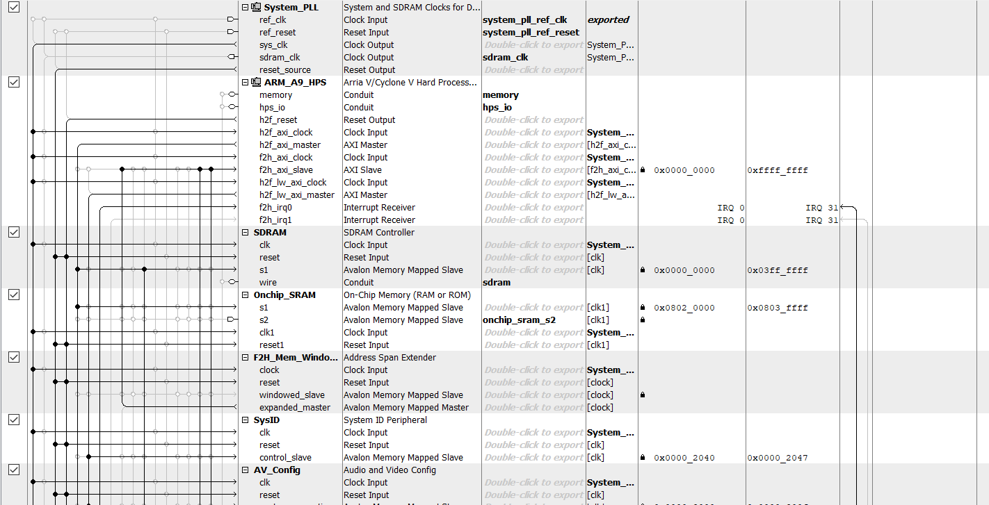
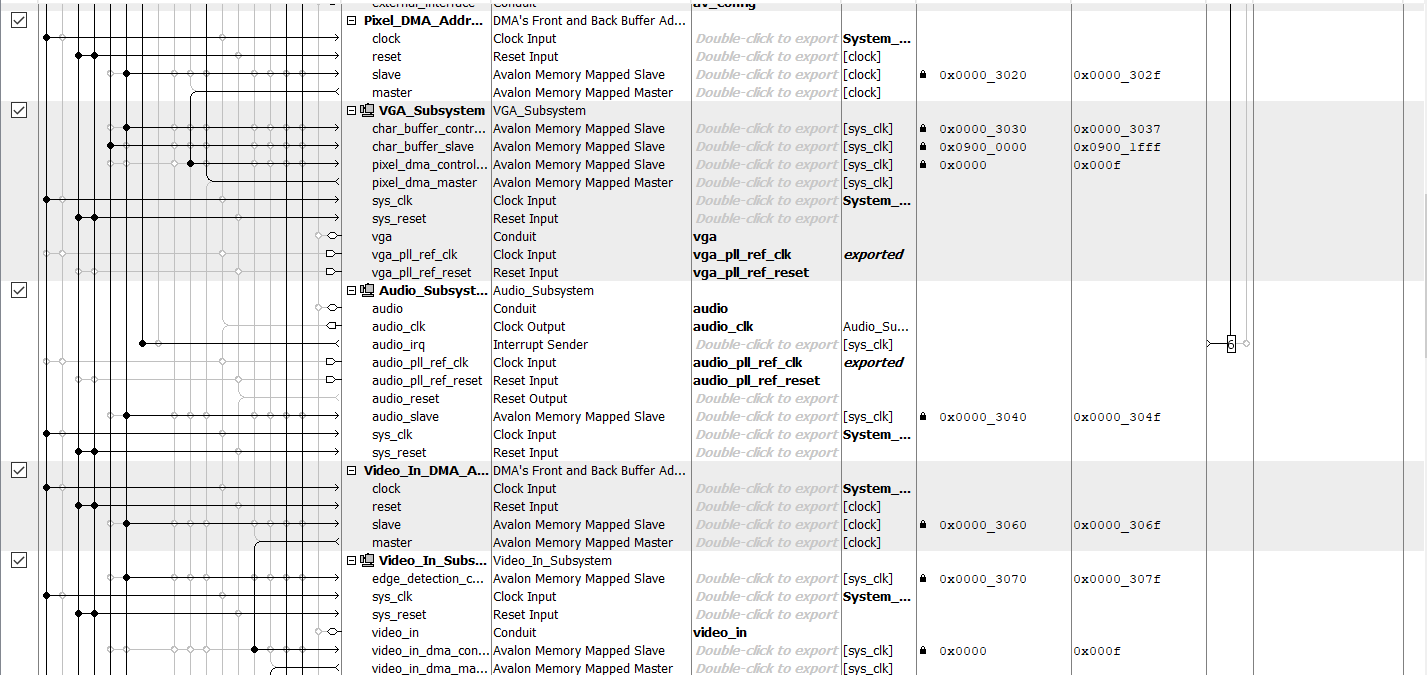
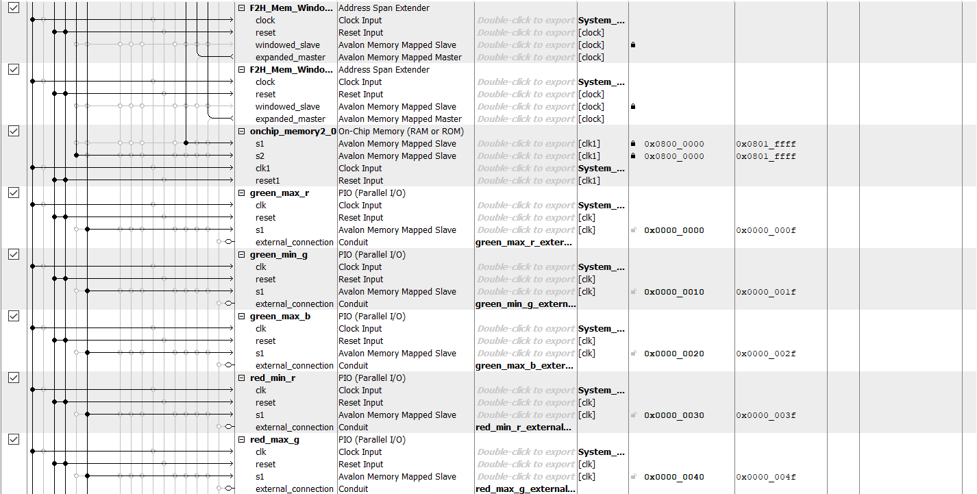
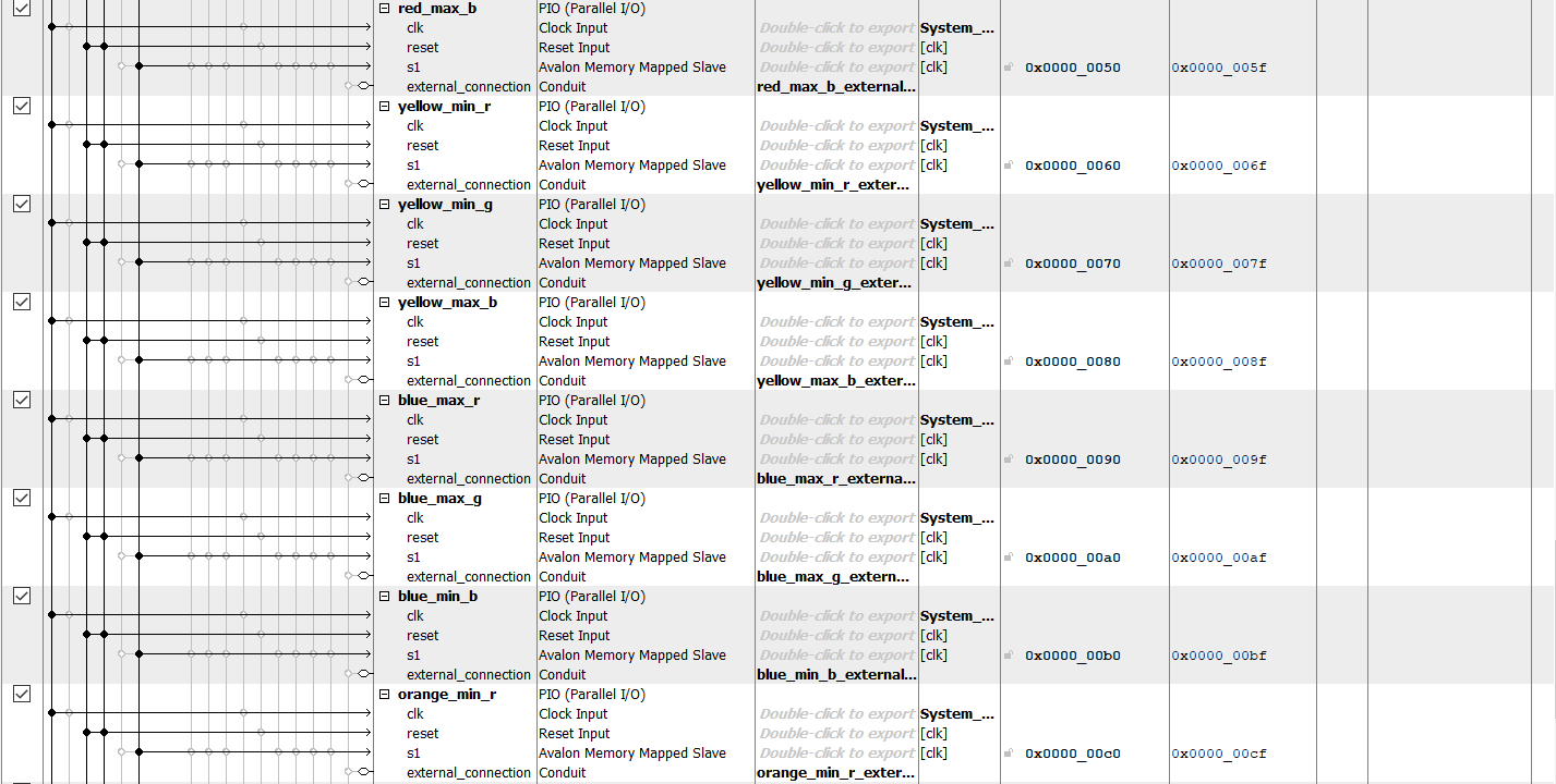
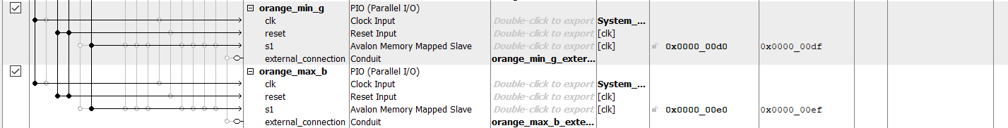
Qsys Configuration
We all have the same class schedule so we were almost always able to be in lab at the same times. We did not divide the work into sections for each of us to complete; instead, we planned and worked on each problem as a group to bounce ideas off each other and debug more easily.
Converting video to SDRAM 640x480 8-bit and 16-bit color starter code
Meet the team:

Jack is an MEng student studying ECE at Cornell University. His areas of interest include all things in digital ASIC design and FPGA development. He will be graduating in the Fall of 2022 and continuing on in the industry as a Design Verification Engineer. In his free time, Jack enjoys singing, as well as playing disc golf and guitar hero (shocking, we know) with his friends.
Dilan is an MEng student studying ECE at Cornell University. His areas of interest include ASIC design and verification. In his free time, Dilan likes to play the drums and hang out outdoors.
Kyle is an MEng student studying ECE at Cornell University. His interests include computer architecture and ASIC design. Kyle enjoys running in his free time