by Sam Cobado, Sofia Conte, Chris Chan
Our project, a simulated pinball machine, allows users to play a classic arcade pinball machine. Using the switches on the FPGA, the player is able to set the initial velocity of the ball which is illustrated via a power bar on the hex displays. The user will then press a button to release the ball into the cabinet, as displayed on a monitor, where it will interact with surrounding objects based on its current velocity and direction. Players can press two other buttons to control each of the two paddles, left and right, in order to try and keep the moving ball in the cabinet. Score is kept based on how long the ball is in play and the game ends when the ball exits the cabinet/display. In addition, the player can toggle a switch on the FPGA to enable/disable an art mode that lets the player draw on the cabinet via the path of the ball.
In order to do this, we have the monitor connected to the FPGA via VGA which displays the movement of the ball and paddles in order for the user to see and control. The FPGA is where all the math happens such as detecting collisions with objects and updating velocities accordingly, moving the paddles based on user input, and actually animating the movements since it has the ability to improve performance through parallel computations. It communicates with the HPS side which keeps track of the score and scoreboard as it is able to take in the name of the player as input after the game is over in order to add them to the current scoreboard.
We decided to pursue this project since we all wanted to be able to create something interactive that we, along with others, could play with. We also thought it would be an interesting challenge to try and simulate something that is inherently very mechanical using the programmable circuitry of the FPGA. Through this project, we were able to learn a lot more about the underlying physics involved with playing pinball. We also gained more experience in designing and programming in Verilog, helping us to also be able to adjust how we view a complex system solely using hardware elements.
For our project, we found inspiration through various classic arcade pinball machines. We all find the game very interesting, and so wanted to stay true to the game as much as possible when simulating on the FPGA. In order to do this, we needed to make sure we included elements such as variable velocity of the initial launch of the ball into the cabinet, the ball interacting with objects in the cabinet, and of course being able to move paddles to keep the ball in play.
The main mathematical considerations for this project has to do with the underlying physics of how the ball moves through the cabinet and interacts with the surrounding walls and objects. Our final implementation has the velocity broken down into its x and y components where the signs are based on how the pixels are labeled on the VGA. Meaning that a negative velocity indicates moving towards 0,0 on the display, or the top left of the screen. Positive velocity therefore means moving towards the bottom right of the screen.
When we launch the ball, we give it an initial velocity in the y-direction, but we do have to consider gravity’s affect on the ball. For example when playing an actual machine, if the ball doesn’t have enough velocity, it falls back onto the spring because of the angle of the cabinet. When considering the physics of a ball moving down an inclined plane without considering other factors such as friction, rolling, sliding, etc, the equation for acceleration is based on the degree of incline of the cabinet. As shown in the diagram below, the direction of acceleration is towards the bottom of the cabinet and is the value gravity * sin of the degree of incline. This means that we need to increment the velocity in the y-direction (as that is towards the bottom of the display) by 1 after a certain number of cycles. While originally we had done the math to determine the cycle threshold based on a 6 degree incline, as we added more and more complexity to our state machine, increasing the number of cycles, we adjusted that cycle threshold manually and stopped when we were satisfied with how it visually looked.
When the ball is then moving around the cabinet, the velocities change in the x and y direction when there is a collision with an object. When a ball bounces off of the stationary object, it leaves at the same angle it hits at with respect to the object.
To calculate this efficiently, all we need is the current velocity vector [x velocity, y velocity] and the unit normal vector of the object we are hitting. Then the new velocity vector is going to calculated using the following equation: v’ = 2*(n dot v)*n + v.
The logical structure of our project follows the logical structure of the game itself. After reset, it starts with setting the initial velocity of the ball using switches 7-0 on the FPGA (the magnitude of initial velocity can be found on our power bar using the hex displays on the FPGA) which represents pulling back the plunger by a certain aount before launching the ball into the cabinet. Then to release the ball, the player needs to press KEY1. Following this is the animation and calculations of how the ball is moving through the cabinet and interacting with the sides and various objects inside. While this is happening, the user is able to press KEY3 and KEY2 to move the left and right paddles respectively just as in the actual game. Holding the button down will keep the paddle in the up position and releasing it will keep it in the low position. The paddles are considered objects in the cabinet as well so the ball will interact with it based on which position it is in. Once the ball has exited the cabinet, the game is over and the HPS side asks the player for their username to add to the score board. The timing/scoring on the HPS side starts when the ball is released to the cabinet and then ends when the game has finished. The overall flow of the logical structure can be found in the block diagram below.
There is very little communication between the FPGA and HPS sides as they operate independently for the most part when the game is in play. Thus, the only signals sent are from the FPGA to the HPS where it indicates when the game starts (game is reset/when the ball is released into the cabinet) which lets the C code to know when to start the timer, and indicates when the game ends (when the ball falls out of the cabinet) telling it to stop the timer and handle the scoreboard.
As there are two different sides to the FPGA we are using, the FPGA side and the HPS side, there are some tradeoffs to consider between what is implemented on the FPGA side using verilog vs the HPS side using C programming. For most of this project, we decided to implement it using the hardware of the FPGA. There are two main reasons for this with the first being this is primarily an FPGA class, so we wanted to use it as much as possible and the second being the ability to perform various logic in parallel and higher clock frequency. For example, by doing collision detection on the FPGA, all the objects can be checked in parallel and we can write to the VGA faster on the FPGA than if we did the drawings on the HPS side.
While we could have chosen to implement timing/scoring on the FPGA side and send the final score to the HPS to display on the terminal, we figured that since we were continuing to change the total number of cycles to go through a single frame of the animation and the clock rate isn’t guaranteed to be exactly what we set it to be, we could have more stability in timing if we did it on the C side. In addition, we could take keyboard input more easily on the C side, display the scoreboard on the terminal, and save the current scoreboard to a file to be loaded in later which is something that FPGA is not capable of doing.
The primary purpose of the HPS in our final project was to create an interactive scoreboard that tracks the scores of the users who have played our pinball game. More specifically, our goal was to create a tracking system that could store scores even through power cycling the board. For this, we configured a scoreboard system that records names and scores to a text file in the same directory as our C code. When the program is loaded, it reads the contents of the text file into a list of entries. When new entries are created, the program writes the entire contents of the list back to the text file.
We have two PIO ports associated with our design:
Both of these are outputs from the FPGA, inputs to the HPS. The pio_reset signal is set HIGH when a ball is launched. The pio_done signal is set HIGH when the ball hits the ground. These two signals govern our score calculation.
The structure that represents each of our scoreboard entries stores a string representing the player’s name, and an integer representing the player’s score. Then the entire scoreboard is stored as an array of entry structs. Here are the data structures that store both of those elements:
When the reset signal is detected, we clock the system time using the gettimeofday() function. We also set a running flag to know that the pinball machine currently has a ball bouncing around. When the ball hits the ground, we clock the system time again. The difference between these two times (in milliseconds) is recorded as the player’s score.
Here is the primary loop that we use to read in scoreboard values from the text file:
We use the fgets() function to read one line of text from the file, and use sscanf() to parse that line into the name and score of the user. Then we create an entry struct to store those pieces of information and assign that entry to an index in the scoreboard array. We then increment the number of entries, which also serves as a pointer to the next free location in the entries array.
When a game has ended, we calculate the user’s score and prompt them to enter a username to be recorded with the score. We log that entry in the local (in program) version of the scoreboard, then we log that entry in the text file version of the scoreboard by writing the updated scoreboard back to the text file. Here is the primary loop that we use to write values back to the scoreboard:
Notice that this loop is almost the exact opposite of the input loop. For each entry in the scoreboard, we take the entry and use its contents to create a string that gets written back to the text file. We then write each string back to the text file using fputs(). After the game is over we also set a waiting flag, so that the game knows there is no ball running, and does not track the elapsed time. When a pinball game is not actively running, the scoreboard program idles until it detects another rising edge of the pio_reset signal.
We write the local and text file scoreboard every time a new entry is created to ensure that they are in sync. Since the text file exists in the file system even after a power cycle, our scoreboard is persistent through reboots meaning that anyone who played the game at any point in time will have their score permanently recorded. Note that the version of the scoreboard stored in the C program is limited to 100 entries, but could easily be expanded by changing the definition of the scoreboard array.
The FPGA side was responsible for performing all of the calculations of simulating the physics behind the game as well as storing the applicable colors to the appropriate location in the M10k block to then be sent to the monitor by the VGA driver. This is accomplished through four main files: collision detection (boundaries), ball properties, drawing and moving paddles, and the main DE1 SoC file.
In the collision detection file, all of the objects and edges of the cabinet are declared as modules that take in an x, y pixel as well as any values needed to determine where the object is located in the cabinet, and then returns a collision flag that is 1 the coordinate falls within the object or 0 if outside. For example, when checking a collision with the top wall, we also need to take in the height of the top wall, and the collision flag is raised only when y <= top wall height. In addition, there is a module used when drawing the initial cabinet. It instantiates the modules for each of the objects, aside from the paddles, and then ORs the collision flags so that it outputs 1 if there is any collision with an object, aside from paddles, and 0 otherwise. This way we can easily tell where objects lie in the cabinet based on the pixels of the display. This exploits the parallelism of the FPGA as the collisions are detected in parallel as opposed to if this was done on the HPS where each collision check would need to be sequential or threaded, posing timing issues when working to create a smooth animation.
Another file contains information about the ball properties which determines the norm of the collided object on collision and updates the x and y velocities accordingly. To determine the norm vectors of the collided object, we instantiate each of the boundary detection modules in the collision detection file. Once we detect a collision, we output the normal vector components for that particular object. For example, the top wall has a normal vector of positive 1 in the y direction and 0 in the x direction (pointing towards the bottom of the cabinet). However, once we see this initial detection, we clear a flag that indicates that we can update the normal vectors and thus, update the velocities. Since we don’t necessarily move the ball a pixel each time this is run, we want to ensure that the direction does not continue to change when the ball remains colliding for multiple steps before it actually moves in the intended direction. This update velocity flag is then only set again once we no longer detect a collision, meaning that we are continuing in the desired direction until the next collision. When we aren’t setting the normal vector to be a specific value, we are setting it to be [0,0] as the resulting calculations for updating velocities would be the current velocities.
The module for updating velocities is purely combinational, takes in the normal vectors and the current velocity, and outputs the resulting value from the equation v’ = 2*(n dot v)*n + v.
To detect collisions with the left and right paddles in their current position, there is a module created in the object boundaries file that takes in the current point, two pixels to check collisions with: one corresponding to the up position and one corresponding to the down position along the width of the paddle (as the collision will only happen with one of the two), and the current position of the paddle (up or down). It then returns if there is a collision with the pixel corresponding to the current position of the paddle. To use this in the normal vectors module, it is instantiated for each pixel along the paddle in a generate statement where the collision flag is a single bit of a wire. Each paddle has it’s own wire of collision bits. This way, if there is a collision with at least one of the pixels, the value of the unsigned wire will be greater than 0, detecting a collision with that specific paddle. The normal vector can then be set according to the current positon state of that paddle. The benefit of looking at the individual pixels as opposed to the paddle as a whole is that there is no simple equation to check if the point overlaps with the paddle that doesn’t involve requiring fixed point math, but using a generate statement allows us to do all the checks in parallel for each of the points while saving DSP blocks.
To draw the paddles themselves, there are two modules, the first is to draw a single paddle and the second is to first erase the paddle and then redraw it, using the first module. The first module is accomplished by taking in a starting point, whether or not we are drawing the left or right paddles, and the inverse slope, and then at each positive edge of the clock, moves to the next pixel of the paddle. It moves in the x-direction based on which paddle we are looking at, and it moves in the y direction after the inverse slope number of steps in the x-direction. If it is in the up position, we move in the -y direction and +y direction otherwise. It raises a flag after moving the specified width in the x direction. The output of the module is the current x and y position.
The second module takes in the current position (up or down) and the new position along with which of the two paddles we are working with. It starts with setting the color to be white and then resetting the draw paddle module taking in the current position as input. This effectively erases the previous paddle. Once the done flag is raised, this process is repeated with the color being black for the new position of the paddle, redrawing it in its new position. Once this is done, it raises a done flag, indicating that the paddle has been erased and redrawn. It outputs the current pixel as well as the current color as this will be used to store into the M10k block in the main verilog file.
The main DE1 SoC file is what contains all of the system information and is also what contains the bulk of our implementation and connects all of these modules together. The base of this was obtained from the course website through the custom VGA example code. We added our main pinball state machine on top of it.
On reset, the initial cabinet is generated. This includes looping through each individual pixel in the display and checking to see if there are any collisions aside from the paddles. If there is a collision, the pixel is colored black, otherwise the pixel is colored white and written to the M10k block. The M10k block is what holds the color for each pixel on the display which is then read by the VGA driver to draw on the monitor. Then the paddles are drawn in the down position (as that is the default position when the keys are not pressed) using the draw paddle module. The state machine then waits for the player to press KEY1 to launch the ball into the cabinet. While waiting, it initializes the ball properties such as the current position of the ball, the current velocity using bits 0-7 of the switches on the FPGA, etc. Once launched, the state machine continues looping through the following steps until the center y position of the ball exceeds the size of the display, i.e. the ball has fallen out of the cabinet. The velocity is updated in the y direction to account for gravity once we have hit a certain number of cycles in that state (the cycle count was adjusted to give the desired appearance when playing the game). The accumulator in the x and y directions are also incremented by the appropriate step. This step is determined by the current velocities in the x and y direction since the velocities are in units of pixels per second, meaning that we can use this value and the clock frequency (100 MHz) to calculate the fraction of a pixel that it is progressing per cycle using 10.10 fixed point representation. Once the accumulator exceeds the threshold, adjusted based on visual appearance, the pixel is either incremented or decremented depending on which direction the ball is moving. Next, the current velocities are updated with the new velocity values (based on the normal vectors determined by collisions).
When the accumulator reaches threshold, the FPGA enters the stages for erasing and redrawing a ball. The FPGA first erases the previous position of the ball, which is saved in a register, by redrawing those pixel locations white. Then, the FSM enters the drawing stage where it draws the turquoise ball at the new pixel location. The filled circle is formed by iterating x and y and writing the position if it's within the circle. Therefore, the FSM stays for 100(diameter squared) cycles in both the erasing and drawing stage. Due to remaining in these stages for many cycles, it was important to synchronize the FSM writing to the VGA with the norm vector updating. When erasing and redrawing, the FPGA should not detect a collision between the ball and walls. Therefore, a register was used as a flag to indicate when the FPGA could detect a collision. This flag was used in the module that found the norm. When this flag was low, the norm was set to zero no matter if the ball was colliding with the wall. When the FSM was in the erasing and drawing stage, this flag was set to low; hence, the norm set to 0. After these stages, the flag is set high, and a collision between a wall and ball can be detected. Another change from a pixel to a circle was that the modules detecting a collision between the ball and wall had to account for the radius of the ball. Setting switch 9 on the FPGA can be used to skip the step of erasing the previous position of the ball. This enables what we refer to as art mode since the player has the ability to draw on the cabinet using the path of the ball.
Once the ball is drawn, we store the previous positon of the paddle and check the state of KEY3 and KEY2 to determine the new position of the paddles. Both paddles are then redrawn accordingly. The described steps then continue to repeat.
The FPGA indicates to the HPS that the game is done when the ball has left the cabinet and then waits for KEY1 to be pressed again to launch another ball into the cabinet.
To display on the screen, we use a custom VGA driver that was provided in the course website for our second lab, meaning that we didn’t need to make any additional changes. It is still worth mentioning what it does though. It utilizes a phased lock loop that runs specifically at 25MHz as the VGA can only run at that maximum speed. When reset, it instantiates the control registers in the driver. At every rising edge of the clock, it indicates the next x and y pixel coordinates that it wants to draw on the VGA. By the next rising edge of the clock, it has the color of that pixel as input to the driver from the M10k block. This color is then connected to the appropriate module outputs that are directly connected to the VGA inputs/outputs. This will always continue to run until reset.
One of the main approaches that we tried, but did not work actually pertained to how we kept track of the velocities. Originally, we took the approach of keeping track of the velocity as a single register and the direction in degrees as a different one. In order to keep track of the x and y components, we used lookup sine and cosine tables that took in the direction, returned the corresponding value, and then we needed to use two multipliers to multiply by the current velocity value. In fact we were able to get initial collisions and movement around the cabinet to work, but when it came to adding in gravity, the problem became a lot more complicated as gravity only affects the y direction, where we would need to perform calculations to update both direction and velocity accordingly. Because of this, we decided to change our approach to the x and y velocities and removing direction register which worked significantly better. This also helped with our collision math because we originally were using the direction vector to determine how the direction as a whole would change on collision since as mentioned earlier, the angle going into the object is the same as leaving the object. However, the math would change based on which direction it was moving in with respect to the object itself, adding more logic for collision detection compared to what we are currently using.
Our other main design that we had to pivot away from was how we detected collisions with the paddles. Originally, we changed our M10k block to be dual ported so that we could read and write in parallel for both the ball logic and VGA driver. We checked the pixel color of the center of the ball to see if it was black. If it was, we knew that we had a collision with a paddle, and depending on which half of the cabinet it was in (when looking at the x-position of the ball), we knew which of the paddles it was hitting. The current position of the paddle determined what the resulting normal vector was for the new velocity calculations. While this actually worked great when we were working with the ball as a single pixel, it posed significantly more problems when we increased the radius of the ball. This resulted in bouncing off of the paddles when the ball appeared to be overlapping with them (since we were detecting at the center of the ball as opposed to the edges) as well as having weird edge cases of the ball passing right through depending on what angle it was travelling it. We believe this edge case was due to erasing the ball and missing the black pixel of the paddle. This is why we transitioned to treating the pixels of the paddles as objects since this would help fix the edge cases and also improve the appearance of the collision.
Most of our testing was accomplished through running the applicable code on the FPGA and looking at the display to see if we were able to achieve the desired results. Therefore, all our results were gained through looking at the VGA monitor and playing the game. Below shows incremental results as we progressed through our implementation.
This also helped us to check the speed of execution by checking to see if we noticed any flicker or lack of smoothness in our animation. Because our animations appeared smooth and the paddles’ responsiveness was almost immediate, it showed us that updating the M10k block with the current frame’s pixel values occurred fast enough that it didn’t seem like it was lagging behind but not too fast as to seem as if the ball was jumping around the screen. If we did notice issues along these lines, we would be able to adjust the frequency of the M10k pll (which is the main clock we used for our calculations and writing to the M10k block) in order to meet the desired timing requirements.
We also visually looked at the animation to see the accuracy of our calculations. For example, when we introduced gravity, we expected to see almost a parabolic shape as it moved across the screen which showed us that the math was done as desired. In addition, we watched the collisions to see visually if the entering angle was the same as the exiting angle with respect to the object collided with. We acknowledge that the calculations won’t be spot on due to fixed point representation and some estimations, but we wanted to make sure that visually, it seemed accurate and true to the original arcade game. However, because we were using visuals to adjust the calculations, this means that the physics is not exact compared to what we would normally see during a regular pinball game. In addition, leaving out some of the other factors such as rolling and friction adds in additional error.
To force stability in our scoring, we moved it from the FPGA to the HPS. This was due to the number of cycles changing in our hardware design and an unstable final clock frequency used on the FPGA. By adding this to the C code, this meant that we could use clock timing in order to determine final score, making it more stable and consistent between runs.
Overall, we feel like our project was a success and are very happy with the results! We were able to simulate the physics of a ball moving through the cabinet, have the player interact with the ball via the paddles controlled through buttons on the FPGA, update the scoreboard with the results from new games, and even add an additional feature of using the ball to create art within the cabinet. We also took time to ensure the quality of our work such as playing the game over and over again to catch any collision edge cases to fix along with continued testing to ensure the scoreboard lasts between game plays and even restarting the C code. In addition, we worked to ensure that the ball moved around the cabinet as expected based on the physics of the game and looked fairly realistic/true to the game. Not only that though, but we also created a project that anyone can play and enjoy. A link to our full demo video can be found below.
One aspect we love about our project is how usable the game is. Almost everyone is able to play it as the controls are fairly simple once the FPGA is set up and programmed since the user only needs to be aware of the switches and buttons on the FPGA and what they control. All feedback of how the game is progressing is found on the monitor including what positions the paddles are in based on user input. Since the response time is very quick between user input and displaying it on the monitor, the usability is quite high. However, those with visual impairments will have a very difficult time playing this game since all the responses and final scoring information is displayed via either the monitor with the cabinet or the terminal with the scoreboard.
Our project differed from our proposal by quite a bit. This was due to not initially realizing the difficulty in implementing this project in Verilog including going down different paths that did not work, resulting in needing to pivot our design and go with a different approach. In addition, we ran into some personal emergencies that resulted in us losing some lab time that could have been used for implementing additional features. For example, in our original proposal, one of the ways we wanted to show the power of the FPGA in being able to run parallel logic and computation is by launching multiple balls into the cabinet at once. Other than this, we accomplished our main goals in the proposal of being able to launch a ball into the cabinet, be able to interact with it using paddles, and use a scoreboard to keep track of all the players of the game. However, we did add an additional feature that was never in our proposal which was art mode. This is something that became apparent as a fun addition as we were working on it.
If given the opportunity to do this project again, we think it would be better to initially abstract the movement and drawing of the ball into a separate module. This way, when it would come time to try to add multiple balls into the cabinet, we could do this way more simply and efficiently. There are also many different avenues to take to expand upon this project in the future. For example, the angle of the cabinet could be changed in order to affect how much gravity affects the movement of the ball within the cabinet. Potentially, other objects of differing materials could be added in there such as a rubber bouncer which would add some velocity to the ball when it hits it, adding more complexity with different physics considerations.
We began our implementation with the custom VGA driver example provided on the course website, but other than that, we did not use any code from any external sources or any additional Altera IP and added/modified the example with our own design and implementation of the simulated pinball machine. Although the design of our cabinet was completely unique to us, there are some intellectual property considerations since there are many commercial games out there that might have a similar layout.
Decisions behind our project had only one main goal: to make the game more fun, easily playable, and more like the actual arcade game. This upholds the IEEE standards of ethics since our decisions were made to avoid injuring others, avoid conflicts of interest, avoid any form of harassment, and to treat all people fairly. In addition, we also sought feedback throughout the project, and were willing to admit our errors and room for improvement for the project which was discussed in this webpage.
/*
* File: Pinball Machine
* Authors: Chris Chan
* Sofia Conte
* Sam Cobado
*/
#include <fcntl.h>
#include <math.h>
#include <stdio.h>
#include <stdlib.h>
#include <string.h>
#include <sys/types.h>
#include <unistd.h>
// interprocess comm
#include <sys/ipc.h>
#include <sys/mman.h>
#include <sys/shm.h>
#include <sys/time.h>
#include <time.h>
// Idk
#include <netdb.h>
#include <netinet/in.h>
#include <sys/socket.h>
////////////////////////////////////////////////
// PIO
////////////////////////////////////////////////
/* Cyclone V FPGA devices */
#define HW_REGS_BASE 0xff200000
// #define HW_REGS_SPAN 0x00200000
#define HW_REGS_SPAN 0x00005000
// Variable drum row PIO port
#define PIO_RESET 0x00000000
#define PIO_DONE 0x00000010
#define PIO_SCORE 0x00000020
// the light weight buss base
void* h2p_lw_virtual_base;
// PIO input buffers
volatile signed int* pio_reset = NULL;
volatile signed int* pio_done = NULL;
int running = 0;
int waiting = 1;
// /dev/mem file id
int fd;
////////////////////////////////////////////////
// Scoreboard
////////////////////////////////////////////////
// Struct that stores one scoreboard entry
typedef struct
{
char name[20]; // Name
int score; // Score
} entry;
// Scoreboard as an array of structs
entry scoreboard[100];
int entries = 0;
/// @brief Print an entry
/// @param e The entry to be printed
void print_entry(entry e)
{
printf("%s - %d\n", e.name, e.score);
}
/// @brief Print out a scoreboard
/// @param scoreboard Pointer to an array of entries
/// @param length Length of the array of entries
void print_scoreboard(entry* scoreboard, int length)
{
int i;
for (i = 0; i < length; i++)
{
entry e = scoreboard[i];
print_entry(e);
}
}
/// @brief Print the welcome message
void print_message()
{
printf("WELCOME TO PINGBALL GAME!\n");
printf("Here are the rules: \n");
printf("A ball will be released on the bottom left "
"corner.\n");
printf("Try to keep the ball from falling and to have it "
"get as many points as possible.\n");
printf("The switchs on the FPGA board control the "
"inital speed of the ball\n");
printf("Press KEY 2 to control the right paddle and KEY3 "
"to control the left paddle\n");
printf("Don't press KEY0 because that resets the whole "
"game \n");
printf("Press KEY1 when you want to release the ball\n");
printf("When the ball falls and the game ends, your "
"score will be printed on the terminal\n");
printf("Just press KEY1 again to play another round\n");
printf("That's all you need to know! Good luck!\n\n");
}
////////////////////////////////////////////////
// Main
////////////////////////////////////////////////
// For timing how long you stay alive
typedef struct timeval timeval_t;
timeval_t start_time, finish_time;
int main(void)
{
////////////////////////////////////////////////
// FPGA Setup
////////////////////////////////////////////////
// === get FPGA addresses ==================
// Open /dev/mem
if ((fd = open("/dev/mem", (O_RDWR | O_SYNC))) == -1)
{
printf("ERROR: could not open \"/dev/mem\"...\n");
return (1);
}
// get virtual addr that maps to physical
h2p_lw_virtual_base = mmap(NULL, HW_REGS_SPAN, (PROT_READ | PROT_WRITE), MAP_SHARED, fd, HW_REGS_BASE);
if (h2p_lw_virtual_base == MAP_FAILED)
{
printf("ERROR: mmap1() failed...\n");
close(fd);
return (1);
}
// PIO Port Setup
pio_reset = (signed int*) (h2p_lw_virtual_base + PIO_RESET);
pio_done = (signed int*) (h2p_lw_virtual_base + PIO_DONE);
////////////////////////////////////////////////
// Scoreboard Setup
////////////////////////////////////////////////
// Print the welcome message
print_message();
// Obtain scoreboard file pointer
FILE* scoreboard_ptr = fopen("scoreboard.txt", "r");
// Input buffer
char line_buffer[100];
// While input from the file is not NULL
while (fgets(line_buffer, 100, scoreboard_ptr) != NULL)
{
// Parse information from the buffer into fields
char name[15];
int score;
sscanf(line_buffer, "%s %d", name, &score);
// Create a struct with those fields
entry e;
memcpy(e.name, name, sizeof(name));
e.score = score;
// Add the entry to the scoreboard
scoreboard[entries] = e;
entries++;
}
// Close the scoreboard file
fclose(scoreboard_ptr);
// Printout score board values
print_scoreboard(scoreboard, entries);
////////////////////////////////////////////////
// while (1)
////////////////////////////////////////////////
while (1)
{
// If reset detected and we are not running yet
if (*pio_reset == 1 && running == 0)
{
// printf("if (*pio_reset == 1 && running == 0)\n");
// Set running to true
running = 1;
waiting = 0;
// Get the starting time
gettimeofday(&start_time, NULL);
}
else if (*pio_done == 1 && waiting == 0)
{
// printf("else if (*pio_done == 1)\n");
// Set running to false
running = 0;
// Log the finish time
gettimeofday(&finish_time, NULL);
// Calculate elapsed time in ms as the score
double elapsed_ms = (finish_time.tv_sec - start_time.tv_sec) * 1e3 + (finish_time.tv_usec - start_time.tv_usec) * 1e-3;
int score = (int) elapsed_ms;
// Print score out to the console
printf("Your score:\t%d\n", score);
// Prompt for user name
char name[20];
printf("Enter New User Name: ");
scanf("%s", name);
// printf("Username: %s\t\tScore: %d\n", name, score);
// Log the entry
entry e;
memcpy(e.name, name, sizeof(name));
e.score = score;
// Add the entry to the scoreboard
scoreboard[entries] = e;
entries += 1;
// Open the scoreboard file again
scoreboard_ptr = fopen("scoreboard.txt", "w+");
// Output buffer
char output_buffer[100];
// Send entries back to scoreboard.txt
int i;
for (i = 0; i < entries; i++)
{
entry e_out = scoreboard[i];
sprintf(output_buffer, "%s %d\n", e_out.name, e_out.score);
fputs(output_buffer, scoreboard_ptr);
}
// Close the scoreboard file
fclose(scoreboard_ptr);
printf("\n++++++++++++++++++++++++++++++++++++++++++++++++\n");
print_scoreboard(scoreboard, entries);
printf("++++++++++++++++++++++++++++++++++++++++++++++++\n");
printf("\npress -> KEY1 <- on the FPGA to play again!\n\n");
waiting = 1;
}
}
}
module DE1_SoC_Computer (
////////////////////////////////////
// FPGA Pins
////////////////////////////////////
// Clock pins
CLOCK_50,
CLOCK2_50,
CLOCK3_50,
CLOCK4_50,
// ADC
ADC_CS_N,
ADC_DIN,
ADC_DOUT,
ADC_SCLK,
// Audio
AUD_ADCDAT,
AUD_ADCLRCK,
AUD_BCLK,
AUD_DACDAT,
AUD_DACLRCK,
AUD_XCK,
// SDRAM
DRAM_ADDR,
DRAM_BA,
DRAM_CAS_N,
DRAM_CKE,
DRAM_CLK,
DRAM_CS_N,
DRAM_DQ,
DRAM_LDQM,
DRAM_RAS_N,
DRAM_UDQM,
DRAM_WE_N,
// I2C Bus for Configuration of the Audio and Video-In Chips
FPGA_I2C_SCLK,
FPGA_I2C_SDAT,
// 40-Pin Headers
GPIO_0,
GPIO_1,
// Seven Segment Displays
HEX0,
HEX1,
HEX2,
HEX3,
HEX4,
HEX5,
// IR
IRDA_RXD,
IRDA_TXD,
// Pushbuttons
KEY,
// LEDs
LEDR,
// PS2 Ports
PS2_CLK,
PS2_DAT,
PS2_CLK2,
PS2_DAT2,
// Slider Switches
SW,
// Video-In
TD_CLK27,
TD_DATA,
TD_HS,
TD_RESET_N,
TD_VS,
// VGA
VGA_B,
VGA_BLANK_N,
VGA_CLK,
VGA_G,
VGA_HS,
VGA_R,
VGA_SYNC_N,
VGA_VS,
////////////////////////////////////
// HPS Pins
////////////////////////////////////
// DDR3 SDRAM
HPS_DDR3_ADDR,
HPS_DDR3_BA,
HPS_DDR3_CAS_N,
HPS_DDR3_CKE,
HPS_DDR3_CK_N,
HPS_DDR3_CK_P,
HPS_DDR3_CS_N,
HPS_DDR3_DM,
HPS_DDR3_DQ,
HPS_DDR3_DQS_N,
HPS_DDR3_DQS_P,
HPS_DDR3_ODT,
HPS_DDR3_RAS_N,
HPS_DDR3_RESET_N,
HPS_DDR3_RZQ,
HPS_DDR3_WE_N,
// Ethernet
HPS_ENET_GTX_CLK,
HPS_ENET_INT_N,
HPS_ENET_MDC,
HPS_ENET_MDIO,
HPS_ENET_RX_CLK,
HPS_ENET_RX_DATA,
HPS_ENET_RX_DV,
HPS_ENET_TX_DATA,
HPS_ENET_TX_EN,
// Flash
HPS_FLASH_DATA,
HPS_FLASH_DCLK,
HPS_FLASH_NCSO,
// Accelerometer
HPS_GSENSOR_INT,
// General Purpose I/O
HPS_GPIO,
// I2C
HPS_I2C_CONTROL,
HPS_I2C1_SCLK,
HPS_I2C1_SDAT,
HPS_I2C2_SCLK,
HPS_I2C2_SDAT,
// Pushbutton
HPS_KEY,
// LED
HPS_LED,
// SD Card
HPS_SD_CLK,
HPS_SD_CMD,
HPS_SD_DATA,
// SPI
HPS_SPIM_CLK,
HPS_SPIM_MISO,
HPS_SPIM_MOSI,
HPS_SPIM_SS,
// UART
HPS_UART_RX,
HPS_UART_TX,
// USB
HPS_CONV_USB_N,
HPS_USB_CLKOUT,
HPS_USB_DATA,
HPS_USB_DIR,
HPS_USB_NXT,
HPS_USB_STP
);
//=======================================================
// PARAMETER declarations
//=======================================================
//=======================================================
// PORT declarations
//=======================================================
////////////////////////////////////
// FPGA Pins
////////////////////////////////////
// Clock pins
input CLOCK_50;
input CLOCK2_50;
input CLOCK3_50;
input CLOCK4_50;
// ADC
inout ADC_CS_N;
output ADC_DIN;
input ADC_DOUT;
output ADC_SCLK;
// Audio
input AUD_ADCDAT;
inout AUD_ADCLRCK;
inout AUD_BCLK;
output AUD_DACDAT;
inout AUD_DACLRCK;
output AUD_XCK;
// SDRAM
output [12: 0] DRAM_ADDR;
output [ 1: 0] DRAM_BA;
output DRAM_CAS_N;
output DRAM_CKE;
output DRAM_CLK;
output DRAM_CS_N;
inout [15: 0] DRAM_DQ;
output DRAM_LDQM;
output DRAM_RAS_N;
output DRAM_UDQM;
output DRAM_WE_N;
// I2C Bus for Configuration of the Audio and Video-In Chips
output FPGA_I2C_SCLK;
inout FPGA_I2C_SDAT;
// 40-pin headers
inout [35: 0] GPIO_0;
inout [35: 0] GPIO_1;
// Seven Segment Displays
output [ 6: 0] HEX0;
output [ 6: 0] HEX1;
output [ 6: 0] HEX2;
output [ 6: 0] HEX3;
output [ 6: 0] HEX4;
output [ 6: 0] HEX5;
// IR
input IRDA_RXD;
output IRDA_TXD;
// Pushbuttons
input [ 3: 0] KEY;
// LEDs
output [ 9: 0] LEDR;
// PS2 Ports
inout PS2_CLK;
inout PS2_DAT;
inout PS2_CLK2;
inout PS2_DAT2;
// Slider Switches
input [ 9: 0] SW;
// Video-In
input TD_CLK27;
input [ 7: 0] TD_DATA;
input TD_HS;
output TD_RESET_N;
input TD_VS;
// VGA
output [ 7: 0] VGA_B;
output VGA_BLANK_N;
output VGA_CLK;
output [ 7: 0] VGA_G;
output VGA_HS;
output [ 7: 0] VGA_R;
output VGA_SYNC_N;
output VGA_VS;
////////////////////////////////////
// HPS Pins
////////////////////////////////////
// DDR3 SDRAM
output [14: 0] HPS_DDR3_ADDR;
output [ 2: 0] HPS_DDR3_BA;
output HPS_DDR3_CAS_N;
output HPS_DDR3_CKE;
output HPS_DDR3_CK_N;
output HPS_DDR3_CK_P;
output HPS_DDR3_CS_N;
output [ 3: 0] HPS_DDR3_DM;
inout [31: 0] HPS_DDR3_DQ;
inout [ 3: 0] HPS_DDR3_DQS_N;
inout [ 3: 0] HPS_DDR3_DQS_P;
output HPS_DDR3_ODT;
output HPS_DDR3_RAS_N;
output HPS_DDR3_RESET_N;
input HPS_DDR3_RZQ;
output HPS_DDR3_WE_N;
// Ethernet
output HPS_ENET_GTX_CLK;
inout HPS_ENET_INT_N;
output HPS_ENET_MDC;
inout HPS_ENET_MDIO;
input HPS_ENET_RX_CLK;
input [ 3: 0] HPS_ENET_RX_DATA;
input HPS_ENET_RX_DV;
output [ 3: 0] HPS_ENET_TX_DATA;
output HPS_ENET_TX_EN;
// Flash
inout [ 3: 0] HPS_FLASH_DATA;
output HPS_FLASH_DCLK;
output HPS_FLASH_NCSO;
// Accelerometer
inout HPS_GSENSOR_INT;
// General Purpose I/O
inout [ 1: 0] HPS_GPIO;
// I2C
inout HPS_I2C_CONTROL;
inout HPS_I2C1_SCLK;
inout HPS_I2C1_SDAT;
inout HPS_I2C2_SCLK;
inout HPS_I2C2_SDAT;
// Pushbutton
inout HPS_KEY;
// LED
inout HPS_LED;
// SD Card
output HPS_SD_CLK;
inout HPS_SD_CMD;
inout [ 3: 0] HPS_SD_DATA;
// SPI
output HPS_SPIM_CLK;
input HPS_SPIM_MISO;
output HPS_SPIM_MOSI;
inout HPS_SPIM_SS;
// UART
input HPS_UART_RX;
output HPS_UART_TX;
// USB
inout HPS_CONV_USB_N;
input HPS_USB_CLKOUT;
inout [ 7: 0] HPS_USB_DATA;
input HPS_USB_DIR;
input HPS_USB_NXT;
output HPS_USB_STP;
//=======================================================
// REG/WIRE declarations
//=======================================================
///inital velocity
reg [9:0] dx = 0;
wire signed [9:0] dy_init;
assign dy_init = SW;
wire [3:0] h1;
wire [3:0] h2;
wire [3:0] h3;
wire [3:0] h4;
wire [3:0] h5;
wire [3:0] h6;
assign h1 = SW[7:0] >10'd_0 ? (SW[7:0] >10'd_1 ? 4'd_8 : 4'd_1) : 4'h_f;
assign h2 = SW[7:0] >10'd_2 ? (SW[7:0] >10'd_4 ? 4'd_8: 4'd_1):4'h_f ;
assign h3 = SW[7:0] >10'd_8 ? (SW[7:0] >10'd_16 ? 4'd_8: 4'd_1):4'h_f ;
assign h4 = SW[7:0] >10'd_32 ? (SW[7:0] >10'd_64 ? 4'd_8: 4'd_1):4'h_f ;
assign h5 = SW[7:0] >10'd_128 ? (SW[7:0] >10'd_256 ? 4'd_8: 4'd_1):4'h_f ;
assign h6 = 4'h_f ;
HexDigit Digit0(HEX0, h1);
HexDigit Digit1(HEX1, h2);
HexDigit Digit2(HEX2, h3);
HexDigit Digit3(HEX3, h4);
HexDigit Digit4(HEX4, h5);
HexDigit Digit5(HEX5, h6);
// VGA clock and reset lines
wire vga_pll_lock;
wire vga_pll;
reg vga_reset;
localparam TRI_W = 10'd_40;
localparam R_WALL = 10'd_531, L_WALL = 10'd_107, T_WALL = 10'd_25;
localparam WALL_W = 10'd_5;
localparam SEC_PER_CYCLE = 29'sd_1;
localparam radius = 10'sd_5;
localparam radius_square = 10'sd_30;
// M10k memory control and data
wire [7:0] M10k_out;
reg [7:0] color_reg;
wire [18:0] write_address;
reg [18:0] read_address;
reg write_enable;
// M10k memory clock
wire M10k_pll;
wire M10k_pll_locked;
// Wires for connecting VGA driver to memory
wire [9:0] next_x;
wire [9:0] next_y;
// wires for connecting iterator to memory
reg [9:0] write_x;
reg [9:0] write_y;
reg [7:0] cur_pixel_color;
wire [7:0] read_color;
wire cabinet_wall;
// details of pinball location and movement
reg [9:0] hold_x, hold_y, ball_x, ball_y;
wire signed [28:0] step_x, step_y;
reg signed [28:0] accum_x, accum_y;
// calculate next pinball velocity
reg signed [19:0] vel_x, vel_y;
wire signed [19:0] next_vel_x, next_vel_y;
wire signed [19:0] norm_x, norm_y;
reg [19:0] cycle_count;
//circle variables
reg signed [9:0] xc;//circle iterators
reg signed [9:0] yc;
wire signed [9:0] xc2;
wire signed [9:0] yc2;
reg signed [9:0] xc_clear;
reg signed [9:0] yc_clear;
wire signed [9:0] xc2_clear;
wire signed [9:0] yc2_clear;
reg [9:0] center_x_clear, center_y_clear;//starting point for clearing
wire [9:0] circle_x;
wire [9:0] circle_y;
wire [9:0] circle_x_clear;
wire [9:0] circle_y_clear;
reg detect_coll;//used to ensure not detecting collision when drawing
reg init;
reg no_update;//b/c unable to detect coll in drawing, need to make sure that if drawing
//is when colliding, don't reenter collision but enter ~update_vell
wire ball_colide;//used to know what to set no_update
reg draw_x;//used to indicate whether to draw new ball
reg draw_y;
assign circle_x = xc + ball_x ;
assign circle_y = (hold_y + yc > 10'd_479)? 10'd_479 : ball_y + yc ;
assign circle_x_clear = xc_clear + center_x_clear ;
assign circle_y_clear = (center_y_clear + yc_clear > 10'd_479)? 10'd_479 : center_y_clear + yc_clear ;
update_velocities up_vel (
.vel_x(vel_x),
.vel_y(vel_y),
.norm_x(norm_x),
.norm_y(norm_y),
.next_vel_x(next_vel_x),
.next_vel_y(next_vel_y)
);
norm_vector find_norm (
.reset(~KEY[0]),
.clk(M10k_pll),
.x(write_x),
.y(write_y),
.l_move_up(l_old_pos),
.r_move_up(r_old_pos),
.R_WALL(R_WALL),
.L_WALL(L_WALL),
.T_WALL(T_WALL),
.TRI_W(TRI_W),
.WALL_W(WALL_W),
.radius(radius),
.detect_coll(detect_coll),
.no_update(no_update),
.norm_x(norm_x),
.norm_y(norm_y)
);
// state of
reg [7:0] state, debug_state;
reg game_over;
// drawing the paddles of the game
wire [9:0] l_paddle_x, l_paddle_y, r_paddle_x, r_paddle_y;
wire l_paddle_done, r_paddle_done;
reg l_reset_paddle, r_reset_paddle;
reg l_old_pos, r_old_pos, l_cur_pos, r_cur_pos;
reg l_update, r_update;
wire [7:0] left_color, right_color;
redraw_paddle redraw_left (
.clk(M10k_pll),
.reset(l_reset_paddle),
.update(l_update),
.left_paddle(1'd_1),
.old_pos(l_old_pos),
.new_pos(l_cur_pos),
.start_x(L_WALL + TRI_W),
.start_y(10'd_480 - TRI_W),
.slope(10'd_4),
.width(10'd_99),
.cur_x(l_paddle_x),
.cur_y(l_paddle_y),
.color_reg(left_color),
.done(l_paddle_done)
);
redraw_paddle redraw_right (
.clk(M10k_pll),
.reset(r_reset_paddle),
.update(r_update),
.left_paddle(1'd_0),
.old_pos(r_old_pos),
.new_pos(r_cur_pos),
.start_x(R_WALL - TRI_W - TRI_W),
.start_y(10'd_480 - TRI_W),
.slope(10'd_4),
.width(10'd_99),
.cur_x(r_paddle_x),
.cur_y(r_paddle_y),
.color_reg(right_color),
.done(r_paddle_done)
);
always@(posedge M10k_pll) begin
if (~KEY[0]) begin // Zero everything in reset
state <= 8'd_1;
vga_reset <= 1'b_1;
write_enable <= 1'd_0;
write_x <= 10'd_0;
write_y <= 10'd_0;
vel_x <= 20'sd_0;
vel_y <= {~{2'd_0, SW[7:0]} + 10'sd_1, 10'd_0};
game_over <= 1'd_0;
cycle_count <= 20'd_0;
r_reset_paddle <= 1'd_1;
l_reset_paddle <= 1'd_1;
l_old_pos <= 1'd_0;
r_old_pos <= 1'd_0;
l_cur_pos <= 1'd_0;
r_cur_pos <= 1'd_0;
r_update <= 1'd_0;
l_update <= 1'd_0;
cur_pixel_color <= 8'b_111_111_11;
debug_state <= 8'd_0;
no_update <= 1'd0;
detect_coll <= 1'd1;
ball_y <= 10'd_479;
ball_x <= (TRI_W - WALL_W)/2 + (R_WALL - TRI_W + WALL_W);
draw_x <= 1'b0;
draw_y <= 1'b0;
center_x_clear <= (TRI_W - WALL_W)/2 + (R_WALL - TRI_W + WALL_W);
center_y_clear <= 10'd_479;
xc <= -radius;
yc <= -radius;
xc_clear <= -radius;
yc_clear <= -radius;
end else begin
// initial drawing of cabinet
if (state == 8'd_1) begin
vga_reset <= 1'b_0;
write_enable <= 1'd_1;
if (cabinet_wall) color_reg <= 8'b_000_000_00; // walls of cabinet are black
else color_reg <= 8'b_111_111_11; // background of cabinet is white
state <= 8'd_2;
end
// in initial drawing, move to next pixel coordinate and repeat process
if (state == 8'd_2) begin
write_enable <= 1'd_0;
if (write_y == 10'd_479) begin
write_y <= 10'd_0;
if (write_x == 10'd_639) begin
write_x <= 10'd_0;
end else begin
write_x <= write_x + 10'd_1;
end
end else begin
write_y <= write_y + 10'd_1;
end
r_reset_paddle <= 1'd_1;
l_reset_paddle <= 1'd_1;
if (write_y == 10'd_479 && write_x == 10'd_639) state <= 8'd_3; // done with initial drawing
else state <= 8'd_1; // repeat
end
if (state == 8'd_3) begin
write_enable <= 1'd_1;
write_x <= l_paddle_x;
write_y <= l_paddle_y;
color_reg <= left_color;
l_reset_paddle <= 1'd_0;
state <= 8'd_4;
end
if (state == 8'd_4) begin // initial drawing of left paddle
color_reg <= left_color;
write_x <= l_paddle_x;
write_y <= l_paddle_y;
r_reset_paddle <= 1'd_1;
if (l_paddle_done) state <= 8'd_5;
else state <= 8'd_4;
end
if (state == 8'd_5) begin
r_reset_paddle <= 1'd_0;
color_reg <= right_color;
write_x <= r_paddle_x;
write_y <= r_paddle_y;
state <= 8'd_6;
end
if (state == 8'd_6) begin // initial drawing of right paddle
write_x <= r_paddle_x;
write_y <= r_paddle_y;
color_reg <= right_color;
if (r_paddle_done) state <= 8'd_7;
else state <= 8'd_6;
end
// intialize ball properties
if (state == 8'd_7) begin
write_enable <= 1'd_0;
color_reg <= 8'b_010_100_10;
write_y <= 10'd_479;
write_x <= (TRI_W - WALL_W)/2 + (R_WALL - TRI_W + WALL_W);
ball_y <= 10'd_479;
ball_x <= (TRI_W - WALL_W)/2 + (R_WALL - TRI_W + WALL_W);
accum_x <= 29'd_0;
accum_y <= 29'd_0;
vel_x <= 20'sd_0;
vel_y <= {~{2'd_0, SW[7:0]} + 10'sd_1, 10'd_0};
cur_pixel_color <= 8'b_111_111_11;
if (~KEY[1]) state <= 8'd_8;
else state <= 8'd_7;
end
if (state == 8'd_8) begin
game_over <= 1'd_0;
write_enable <= 1'd_0;
vel_x <= next_vel_x;
if (cycle_count == 20'd_24) begin
cycle_count <= 20'd_0;
vel_y <= next_vel_y + 20'sd_5;
end else begin
vel_y <= next_vel_y;
cycle_count <= cycle_count + 20'd_1;
end
if (accum_y >= 29'sd_167772) begin
accum_y <= accum_y - 29'd_167772 + step_y;
write_y <= write_y + 10'd_1;
ball_y <= ball_y + 10'd_1;
draw_y <= 1'b1;
end else if (accum_y <= -29'sd_167772) begin
accum_y <= accum_y + 29'd_167772 + step_y;
write_y <= write_y - 10'd_1;
ball_y <= ball_y - 10'd_1;
draw_y <= 1'b1;
end else begin
accum_y <= accum_y + step_y;
draw_y <= 1'b0;
end
if (accum_x >= 29'sd_167772) begin
accum_x <= accum_x - 29'd_167772 + step_x;
write_x <= write_x + 10'd_1;
ball_x <= ball_x + 10'd_1;
draw_x <= 1'b1;
end else if (accum_x <= -29'sd_167772) begin
accum_x <= accum_x + 29'd_167772 + step_x;
write_x <= write_x - 10'd_1;
ball_x <= ball_x - 10'd_1;
draw_x <= 1'b1;
end else begin
accum_x <= accum_x + step_x;
draw_x <= 1'b0;
end
l_reset_paddle <= 1'd_1;
xc <= -radius;//reset iterators for drawing circles
yc <= -radius;
xc_clear <= -radius;
yc_clear <= -radius;
if (accum_y >= 29'sd_167772 && write_y == 10'd_479)begin
state <= 8'd_21;
end
else begin
state <= 8'd_9;
end
detect_coll <= 1'b0;
end
if (state == 8'd_9) begin
write_enable <= 1'd_1;
vel_x <= next_vel_x;
vel_y <= next_vel_y;
write_x <= ball_x;
write_y <= ball_y;
if(draw_x || draw_y) begin//draw new ball position
state <= 8'd_17;
end
else begin
state <= 8'd_10;
end
end
if (state == 8'd_10) begin
hold_x <= write_x;
hold_y <= write_y;
l_reset_paddle <= 1'd_1;
l_cur_pos <= ~KEY[3];
l_update <= ~(~KEY[3] == l_old_pos);
state <= 8'd_13;
end
if (state == 8'd_13) begin
write_x <= l_paddle_x;
write_y <= l_paddle_y;
color_reg <= left_color;
l_reset_paddle <= 1'd_0;
state <= 8'd_14;
end
if (state == 8'd_14) begin
color_reg <= left_color;
write_x <= l_paddle_x;
write_y <= l_paddle_y;
r_reset_paddle <= 1'd_1;
r_cur_pos <= ~KEY[2];
r_update <= ~(~KEY[2] == r_old_pos);
if (l_paddle_done) begin
l_old_pos <= l_cur_pos;
state <= 8'd_15;
end else state <= 8'd_14;
end
if (state == 8'd_15) begin
r_reset_paddle <= 1'd_0;
color_reg <= right_color;
write_x <= r_paddle_x;
write_y <= r_paddle_y;
state <= 8'd_16;
end
if (state == 8'd_16) begin
if (r_paddle_done) begin
r_old_pos <= r_cur_pos;
write_x <= hold_x;
write_y <= hold_y;
color_reg <= 8'b_010_100_10;
write_enable <= 1'd_0;
detect_coll <= 1'd1; //set to 1 so that in stage 8 detects collisions
state <= 8'd_8;
end else begin
write_x <= r_paddle_x;
write_y <= r_paddle_y;
color_reg <= right_color;
state <= 8'd_16;
end
end
//transition state
if(state == 8'd17) begin
if (SW[9]) begin
state <= 8'd18;//change to 18 to skip clearing
write_x <= ball_x;
write_y <= ball_y;
color_reg <= 8'b_010_100_10;
end else begin
state <= 8'd19;//change to 19 if you want to clear before writing
color_reg <= 8'b_111_111_11;
end
end
//draw ball
if(state == 8'd_18)begin
color_reg <= 8'b_010_100_10;
draw_y <= 1'b0;
draw_x <= 1'b0;
center_y_clear <= ball_y;
center_x_clear <= ball_x;
if(xc2 + yc2 <= radius_square)begin
write_x <= circle_x;
write_y <= circle_y;
end
if(xc == radius) begin
xc <= -radius;
yc <= yc + 10'sd_1;
end
else begin
xc <= xc + 10'sd_1;
yc <= yc;
end
if((xc == radius) & (yc == radius)) begin
state <= 8'd_9;
end
else begin
state <= 8'd_18;
end
end
//clear ball
if(state == 8'd_19)begin
color_reg <= 8'b_111_111_11;
if(xc2_clear + yc2_clear <= radius_square)begin
write_x <= circle_x_clear;
write_y <= circle_y_clear;
end
if(xc_clear == radius) begin
xc_clear <= -radius;
yc_clear <= yc_clear + 10'sd_1;
end
else begin
xc_clear <= xc_clear + 10'sd_1;
yc_clear <= yc_clear;
end
if((xc_clear == radius) & (yc_clear == radius)) begin
state <= 8'd18;
write_x <= ball_x;
write_y <= ball_y;
end
else begin
state <= 8'd_19;
end
end
if (state == 8'd_21) begin
game_over <= 1'd_1;
cycle_count <= 20'd_0;
r_reset_paddle <= 1'd_1;
l_reset_paddle <= 1'd_1;
l_old_pos <= 1'd_0;
r_old_pos <= 1'd_0;
l_cur_pos <= 1'd_0;
r_cur_pos <= 1'd_0;
r_update <= 1'd_0;
l_update <= 1'd_0;
cur_pixel_color <= 8'b_111_111_11;
debug_state <= 8'd_0;
detect_coll <= 1'd1;
draw_x <= 1'b0;
draw_y <= 1'b0;
center_x_clear <= (TRI_W - WALL_W)/2 + (R_WALL - TRI_W + WALL_W);
center_y_clear <= 10'd_479;
xc <= -radius;
yc <= -radius;
xc_clear <= -radius;
yc_clear <= -radius;
write_enable <= 1'd_0;
color_reg <= 8'b_010_100_10;
write_y <= 10'd_479;
write_x <= (TRI_W - WALL_W)/2 + (R_WALL - TRI_W + WALL_W);
ball_y <= 10'd_479;
ball_x <= (TRI_W - WALL_W)/2 + (R_WALL - TRI_W + WALL_W);
accum_x <= 29'd_0;
accum_y <= 29'd_0;
vel_x <= 20'sd_0;
vel_y <= {~{2'd_0, SW[7:0]} + 10'sd_1, 10'd_0};
cur_pixel_color <= 8'b_111_111_11;
if (~KEY[1]) state <= 8'd_8;
else state <= 8'd_21;
end
end
end
detect_collision init_cabinet (
.x(write_x),
.y(write_y),
.TRI_W(TRI_W),
.R_WALL(R_WALL),
.L_WALL(L_WALL),
.T_WALL(T_WALL),
.WALL_W(WALL_W),
.collision(cabinet_wall)
);
signed_mult calc_step_y (
.out(step_y),
.a(SEC_PER_CYCLE),
.b(vel_y)
);
signed_mult calc_step_x (
.out(step_x),
.a(SEC_PER_CYCLE),
.b(vel_x)
);
circle_signed_mult cx (
.out(xc2),
.a(xc),
.b(xc)
);
circle_signed_mult cy (
.out(yc2),
.a(yc),
.b(yc)
);
circle_signed_mult cx_clear (
.out(xc2_clear),
.a(xc_clear),
.b(xc_clear)
);
circle_signed_mult cy_clear (
.out(yc2_clear),
.a(yc_clear),
.b(yc_clear)
);
M10K_1000_8 pixel_data(
.data_a(color_reg), // a is for pixel writing
.q_a(read_color),
.addr_a((19'd_640*write_y) + write_x),
.we_a(write_enable),
.data_b(8'd_0), // b is for the VGA controls
.q_b(M10k_out),
.addr_b((19'd_640*next_y) + next_x),
.we_b(1'd_0),
.clk(M10k_pll)
);
// Instantiate VGA driver
vga_driver driver(
.clock(vga_pll),
.reset(vga_reset),
.color_in(M10k_out), // Pixel color (8-bit) from memory
.next_x(next_x), // This (and next_y) used to specify memory read address
.next_y(next_y), // This (and next_x) used to specify memory read address
.hsync(VGA_HS),
.vsync(VGA_VS),
.red(VGA_R),
.green(VGA_G),
.blue(VGA_B),
.sync(VGA_SYNC_N),
.clk(VGA_CLK),
.blank(VGA_BLANK_N)
);
//=======================================================
// Structural coding
//=======================================================
// From Qsys
Computer_System The_System (
////////////////////////////////////
// FPGA Side
////////////////////////////////////
.vga_pio_locked_export (vga_pll_lock), // vga_pio_locked.export
.vga_pio_outclk0_clk (vga_pll), // vga_pio_outclk0.clk
.m10k_pll_locked_export (M10k_pll_locked), // m10k_pll_locked.export
.m10k_pll_outclk0_clk (M10k_pll), // m10k_pll_outclk0.clk
// Global signals
.system_pll_ref_clk_clk (CLOCK_50),
.system_pll_ref_reset_reset (1'b0),
////////////////////////////////////
// HPS Side
////////////////////////////////////
// DDR3 SDRAM
.memory_mem_a (HPS_DDR3_ADDR),
.memory_mem_ba (HPS_DDR3_BA),
.memory_mem_ck (HPS_DDR3_CK_P),
.memory_mem_ck_n (HPS_DDR3_CK_N),
.memory_mem_cke (HPS_DDR3_CKE),
.memory_mem_cs_n (HPS_DDR3_CS_N),
.memory_mem_ras_n (HPS_DDR3_RAS_N),
.memory_mem_cas_n (HPS_DDR3_CAS_N),
.memory_mem_we_n (HPS_DDR3_WE_N),
.memory_mem_reset_n (HPS_DDR3_RESET_N),
.memory_mem_dq (HPS_DDR3_DQ),
.memory_mem_dqs (HPS_DDR3_DQS_P),
.memory_mem_dqs_n (HPS_DDR3_DQS_N),
.memory_mem_odt (HPS_DDR3_ODT),
.memory_mem_dm (HPS_DDR3_DM),
.memory_oct_rzqin (HPS_DDR3_RZQ),
// Ethernet
.hps_io_hps_io_gpio_inst_GPIO35 (HPS_ENET_INT_N),
.hps_io_hps_io_emac1_inst_TX_CLK (HPS_ENET_GTX_CLK),
.hps_io_hps_io_emac1_inst_TXD0 (HPS_ENET_TX_DATA[0]),
.hps_io_hps_io_emac1_inst_TXD1 (HPS_ENET_TX_DATA[1]),
.hps_io_hps_io_emac1_inst_TXD2 (HPS_ENET_TX_DATA[2]),
.hps_io_hps_io_emac1_inst_TXD3 (HPS_ENET_TX_DATA[3]),
.hps_io_hps_io_emac1_inst_RXD0 (HPS_ENET_RX_DATA[0]),
.hps_io_hps_io_emac1_inst_MDIO (HPS_ENET_MDIO),
.hps_io_hps_io_emac1_inst_MDC (HPS_ENET_MDC),
.hps_io_hps_io_emac1_inst_RX_CTL (HPS_ENET_RX_DV),
.hps_io_hps_io_emac1_inst_TX_CTL (HPS_ENET_TX_EN),
.hps_io_hps_io_emac1_inst_RX_CLK (HPS_ENET_RX_CLK),
.hps_io_hps_io_emac1_inst_RXD1 (HPS_ENET_RX_DATA[1]),
.hps_io_hps_io_emac1_inst_RXD2 (HPS_ENET_RX_DATA[2]),
.hps_io_hps_io_emac1_inst_RXD3 (HPS_ENET_RX_DATA[3]),
// Flash
.hps_io_hps_io_qspi_inst_IO0 (HPS_FLASH_DATA[0]),
.hps_io_hps_io_qspi_inst_IO1 (HPS_FLASH_DATA[1]),
.hps_io_hps_io_qspi_inst_IO2 (HPS_FLASH_DATA[2]),
.hps_io_hps_io_qspi_inst_IO3 (HPS_FLASH_DATA[3]),
.hps_io_hps_io_qspi_inst_SS0 (HPS_FLASH_NCSO),
.hps_io_hps_io_qspi_inst_CLK (HPS_FLASH_DCLK),
// Accelerometer
.hps_io_hps_io_gpio_inst_GPIO61 (HPS_GSENSOR_INT),
//.adc_sclk (ADC_SCLK),
//.adc_cs_n (ADC_CS_N),
//.adc_dout (ADC_DOUT),
//.adc_din (ADC_DIN),
// General Purpose I/O
.hps_io_hps_io_gpio_inst_GPIO40 (HPS_GPIO[0]),
.hps_io_hps_io_gpio_inst_GPIO41 (HPS_GPIO[1]),
// I2C
.hps_io_hps_io_gpio_inst_GPIO48 (HPS_I2C_CONTROL),
.hps_io_hps_io_i2c0_inst_SDA (HPS_I2C1_SDAT),
.hps_io_hps_io_i2c0_inst_SCL (HPS_I2C1_SCLK),
.hps_io_hps_io_i2c1_inst_SDA (HPS_I2C2_SDAT),
.hps_io_hps_io_i2c1_inst_SCL (HPS_I2C2_SCLK),
// Pushbutton
.hps_io_hps_io_gpio_inst_GPIO54 (HPS_KEY),
// LED
.hps_io_hps_io_gpio_inst_GPIO53 (HPS_LED),
// SD Card
.hps_io_hps_io_sdio_inst_CMD (HPS_SD_CMD),
.hps_io_hps_io_sdio_inst_D0 (HPS_SD_DATA[0]),
.hps_io_hps_io_sdio_inst_D1 (HPS_SD_DATA[1]),
.hps_io_hps_io_sdio_inst_CLK (HPS_SD_CLK),
.hps_io_hps_io_sdio_inst_D2 (HPS_SD_DATA[2]),
.hps_io_hps_io_sdio_inst_D3 (HPS_SD_DATA[3]),
// SPI
.hps_io_hps_io_spim1_inst_CLK (HPS_SPIM_CLK),
.hps_io_hps_io_spim1_inst_MOSI (HPS_SPIM_MOSI),
.hps_io_hps_io_spim1_inst_MISO (HPS_SPIM_MISO),
.hps_io_hps_io_spim1_inst_SS0 (HPS_SPIM_SS),
// UART
.hps_io_hps_io_uart0_inst_RX (HPS_UART_RX),
.hps_io_hps_io_uart0_inst_TX (HPS_UART_TX),
// USB
.hps_io_hps_io_gpio_inst_GPIO09 (HPS_CONV_USB_N),
.hps_io_hps_io_usb1_inst_D0 (HPS_USB_DATA[0]),
.hps_io_hps_io_usb1_inst_D1 (HPS_USB_DATA[1]),
.hps_io_hps_io_usb1_inst_D2 (HPS_USB_DATA[2]),
.hps_io_hps_io_usb1_inst_D3 (HPS_USB_DATA[3]),
.hps_io_hps_io_usb1_inst_D4 (HPS_USB_DATA[4]),
.hps_io_hps_io_usb1_inst_D5 (HPS_USB_DATA[5]),
.hps_io_hps_io_usb1_inst_D6 (HPS_USB_DATA[6]),
.hps_io_hps_io_usb1_inst_D7 (HPS_USB_DATA[7]),
.hps_io_hps_io_usb1_inst_CLK (HPS_USB_CLKOUT),
.hps_io_hps_io_usb1_inst_STP (HPS_USB_STP),
.hps_io_hps_io_usb1_inst_DIR (HPS_USB_DIR),
.hps_io_hps_io_usb1_inst_NXT (HPS_USB_NXT),
// inputs to ARM from FPGA
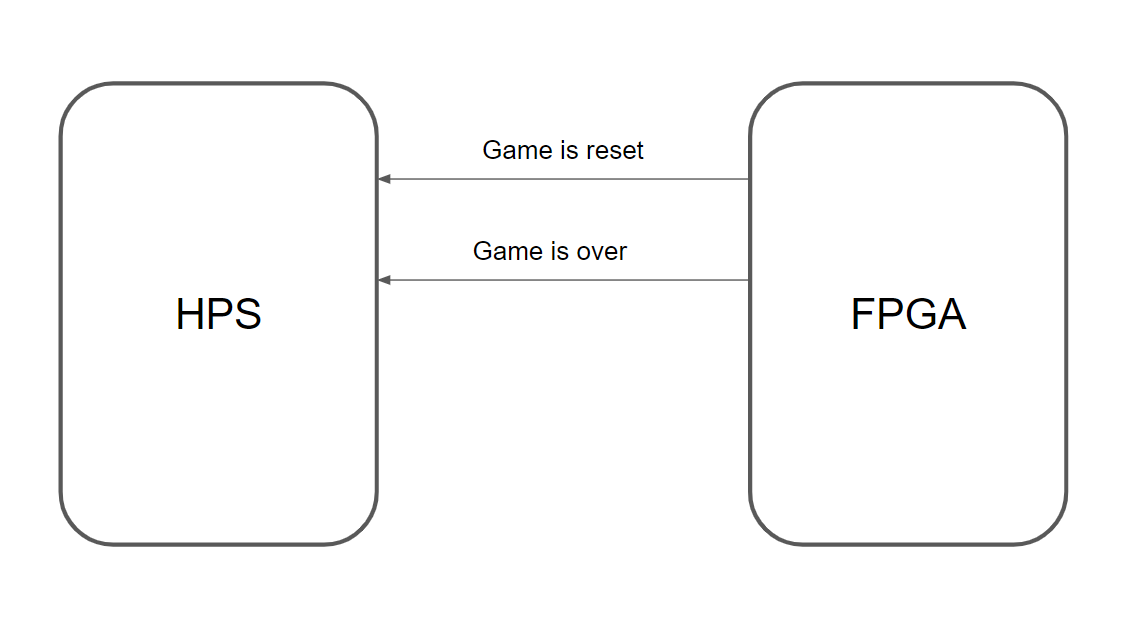
.reset_game_export({31'd_0, (~KEY[0] | ~KEY[1])}),
.game_done_export({31'd_0, game_over}),
.score_export(32'd_0)
);
endmodule // end top level
// Declaration of module, include width and signedness of each input/output
module vga_driver (
input wire clock,
input wire reset,
input [7:0] color_in,
output [9:0] next_x,
output [9:0] next_y,
output wire hsync,
output wire vsync,
output [7:0] red,
output [7:0] green,
output [7:0] blue,
output sync,
output clk,
output blank
);
// Horizontal parameters (measured in clock cycles)
parameter [9:0] H_ACTIVE = 10'd_639 ;
parameter [9:0] H_FRONT = 10'd_15 ;
parameter [9:0] H_PULSE = 10'd_95 ;
parameter [9:0] H_BACK = 10'd_47 ;
// Vertical parameters (measured in lines)
parameter [9:0] V_ACTIVE = 10'd_479 ;
parameter [9:0] V_FRONT = 10'd_9 ;
parameter [9:0] V_PULSE = 10'd_1 ;
parameter [9:0] V_BACK = 10'd_32 ;
// // Horizontal parameters (measured in clock cycles)
// parameter [9:0] H_ACTIVE = 10'd_9 ;
// parameter [9:0] H_FRONT = 10'd_4 ;
// parameter [9:0] H_PULSE = 10'd_4 ;
// parameter [9:0] H_BACK = 10'd_4 ;
// parameter [9:0] H_TOTAL = 10'd_799 ;
//
// // Vertical parameters (measured in lines)
// parameter [9:0] V_ACTIVE = 10'd_1 ;
// parameter [9:0] V_FRONT = 10'd_1 ;
// parameter [9:0] V_PULSE = 10'd_1 ;
// parameter [9:0] V_BACK = 10'd_1 ;
// Parameters for readability
parameter LOW = 1'b_0 ;
parameter HIGH = 1'b_1 ;
// States (more readable)
parameter [7:0] H_ACTIVE_STATE = 8'd_0 ;
parameter [7:0] H_FRONT_STATE = 8'd_1 ;
parameter [7:0] H_PULSE_STATE = 8'd_2 ;
parameter [7:0] H_BACK_STATE = 8'd_3 ;
parameter [7:0] V_ACTIVE_STATE = 8'd_0 ;
parameter [7:0] V_FRONT_STATE = 8'd_1 ;
parameter [7:0] V_PULSE_STATE = 8'd_2 ;
parameter [7:0] V_BACK_STATE = 8'd_3 ;
// Clocked registers
reg hysnc_reg ;
reg vsync_reg ;
reg [7:0] red_reg ;
reg [7:0] green_reg ;
reg [7:0] blue_reg ;
reg line_done ;
// Control registers
reg [9:0] h_counter ;
reg [9:0] v_counter ;
reg [7:0] h_state ;
reg [7:0] v_state ;
// State machine
always@(posedge clock) begin
// At reset . . .
if (reset) begin
// Zero the counters
h_counter <= 10'd_0 ;
v_counter <= 10'd_0 ;
// States to ACTIVE
h_state <= H_ACTIVE_STATE ;
v_state <= V_ACTIVE_STATE ;
// Deassert line done
line_done <= LOW ;
end
else begin
//////////////////////////////////////////////////////////////////////////
///////////////////////// HORIZONTAL /////////////////////////////////////
//////////////////////////////////////////////////////////////////////////
if (h_state == H_ACTIVE_STATE) begin
// Iterate horizontal counter, zero at end of ACTIVE mode
h_counter <= (h_counter==H_ACTIVE)?10'd_0:(h_counter + 10'd_1) ;
// Set hsync
hysnc_reg <= HIGH ;
// Deassert line done
line_done <= LOW ;
// State transition
h_state <= (h_counter == H_ACTIVE)?H_FRONT_STATE:H_ACTIVE_STATE ;
end
// Assert done flag, wait here for reset
if (h_state == H_FRONT_STATE) begin
// Iterate horizontal counter, zero at end of H_FRONT mode
h_counter <= (h_counter==H_FRONT)?10'd_0:(h_counter + 10'd_1) ;
// Set hsync
hysnc_reg <= HIGH ;
// State transition
h_state <= (h_counter == H_FRONT)?H_PULSE_STATE:H_FRONT_STATE ;
end
if (h_state == H_PULSE_STATE) begin
// Iterate horizontal counter, zero at end of H_FRONT mode
h_counter <= (h_counter==H_PULSE)?10'd_0:(h_counter + 10'd_1) ;
// Set hsync
hysnc_reg <= LOW ;
// State transition
h_state <= (h_counter == H_PULSE)?H_BACK_STATE:H_PULSE_STATE ;
end
if (h_state == H_BACK_STATE) begin
// Iterate horizontal counter, zero at end of H_FRONT mode
h_counter <= (h_counter==H_BACK)?10'd_0:(h_counter + 10'd_1) ;
// Set hsync
hysnc_reg <= HIGH ;
// State transition
h_state <= (h_counter == H_BACK)?H_ACTIVE_STATE:H_BACK_STATE ;
// Signal line complete at state transition (offset by 1 for synchronous state transition)
line_done <= (h_counter == (H_BACK-1))?HIGH:LOW ;
end
//////////////////////////////////////////////////////////////////////////
///////////////////////// VERTICAL ///////////////////////////////////////
//////////////////////////////////////////////////////////////////////////
if (v_state == V_ACTIVE_STATE) begin
// increment vertical counter at end of line, zero on state transition
v_counter <= (line_done==HIGH)?((v_counter==V_ACTIVE)?10'd_0:(v_counter + 10'd_1)):v_counter ;
// set vsync in active mode
vsync_reg <= HIGH ;
// state transition - only on end of lines
v_state <= (line_done==HIGH)?((v_counter==V_ACTIVE)?V_FRONT_STATE:V_ACTIVE_STATE):V_ACTIVE_STATE ;
end
if (v_state == V_FRONT_STATE) begin
// increment vertical counter at end of line, zero on state transition
v_counter <= (line_done==HIGH)?((v_counter==V_FRONT)?10'd_0:(v_counter + 10'd_1)):v_counter ;
// set vsync in front porch
vsync_reg <= HIGH ;
// state transition
v_state <= (line_done==HIGH)?((v_counter==V_FRONT)?V_PULSE_STATE:V_FRONT_STATE):V_FRONT_STATE ;
end
if (v_state == V_PULSE_STATE) begin
// increment vertical counter at end of line, zero on state transition
v_counter <= (line_done==HIGH)?((v_counter==V_PULSE)?10'd_0:(v_counter + 10'd_1)):v_counter ;
// clear vsync in pulse
vsync_reg <= LOW ;
// state transition
v_state <= (line_done==HIGH)?((v_counter==V_PULSE)?V_BACK_STATE:V_PULSE_STATE):V_PULSE_STATE ;
end
if (v_state == V_BACK_STATE) begin
// increment vertical counter at end of line, zero on state transition
v_counter <= (line_done==HIGH)?((v_counter==V_BACK)?10'd_0:(v_counter + 10'd_1)):v_counter ;
// set vsync in back porch
vsync_reg <= HIGH ;
// state transition
v_state <= (line_done==HIGH)?((v_counter==V_BACK)?V_ACTIVE_STATE:V_BACK_STATE):V_BACK_STATE ;
end
//////////////////////////////////////////////////////////////////////////
//////////////////////////////// COLOR OUT ///////////////////////////////
//////////////////////////////////////////////////////////////////////////
red_reg <= (h_state==H_ACTIVE_STATE)?((v_state==V_ACTIVE_STATE)?{color_in[7:5],5'd_0}:8'd_0):8'd_0 ;
green_reg <= (h_state==H_ACTIVE_STATE)?((v_state==V_ACTIVE_STATE)?{color_in[4:2],5'd_0}:8'd_0):8'd_0 ;
blue_reg <= (h_state==H_ACTIVE_STATE)?((v_state==V_ACTIVE_STATE)?{color_in[1:0],6'd_0}:8'd_0):8'd_0 ;
end
end
// Assign output values
assign hsync = hysnc_reg ;
assign vsync = vsync_reg ;
assign red = red_reg ;
assign green = green_reg ;
assign blue = blue_reg ;
assign clk = clock ;
assign sync = 1'b_0 ;
assign blank = hysnc_reg & vsync_reg ;
// The x/y coordinates that should be available on the NEXT cycle
assign next_x = (h_state==H_ACTIVE_STATE)?h_counter:10'd_0 ;
assign next_y = (v_state==V_ACTIVE_STATE)?v_counter:10'd_0 ;
endmodule
//============================================================
// M10K module for testing
//============================================================
// See example 12-16 in
// http://people.ece.cornell.edu/land/courses/ece5760/DE1_SOC/HDL_style_qts_qii51007.pdf
//============================================================
module M10K_1000_8 (
input [7:0] data_a, data_b,
input [18:0] addr_a, addr_b,
input we_a, we_b, clk,
output reg [7:0] q_a, q_b
);
// Declare the RAM variable
reg [7:0] ram[307200:0]; /* synthesis ramstyle = "no_rw_check, M10K" */
// Port A
always @ (posedge clk)
begin
if (we_a)
begin
ram[addr_a] = data_a;
end
q_a <= ram[addr_a];
end
// Port B
always @ (posedge clk)
begin
if (we_b)
begin
ram[addr_b] = data_b;
end
q_b <= ram[addr_b];
end
endmodule
module signed_mult (out, a, b);
output signed [28:0] out;
input signed [28:0] a;
input signed [19:0] b;
// intermediate full bit length
wire signed [48:0] mult_out;
assign mult_out = a * b;
// select bits for 2.27 fixed point
assign out = {mult_out[48], mult_out[37:10]};
endmodule
module calc_vel (out, a, b);
output signed [19:0] out;
input signed [19:0] a;
input signed [10:0] b;
// intermediate full bit length
wire signed [29:0] mult_out;
assign mult_out = a * b;
// select bits for 2.27 fixed point
assign out = {mult_out[29], mult_out[18:0]};
endmodule
//used when drawing circle
module circle_signed_mult (out, a, b);
output signed [9:0] out;
input signed [9:0] a;
input signed [9:0] b;
// intermediate full bit length
wire signed [19:0] mult_out;
assign mult_out = a * b;
// select bits for 2.27 fixed point
assign out = {mult_out[19], mult_out[8:0]};
endmodule
//
// Detect collision with any object based on current position
//
module detect_collision (x, y, TRI_W, R_WALL, L_WALL, T_WALL, WALL_W, collision);
input [9:0] x, y;
input [9:0] TRI_W, R_WALL, L_WALL, T_WALL, WALL_W;
output collision;
// detect collision with right wall
wire col_r_wall;
collide_r_wall crw (
.x(x),
.y(y),
.R_WALL(R_WALL),
.collision(col_r_wall)
);
// detect collision with left wall
wire col_l_wall;
collide_l_wall clw (
.x(x),
.y(y),
.L_WALL(L_WALL),
.collision(col_l_wall)
);
// detect collision with top wall
wire col_t_wall;
collide_t_wall ctw (
.x(x),
.y(y),
.T_WALL(T_WALL),
.collision(col_t_wall)
);
// detect collision with top right triangle
wire col_tr_tri;
collide_tr_tri ctrt (
.x(x),
.y(y),
.R_WALL(R_WALL),
.TRI_W(TRI_W),
.T_WALL(T_WALL),
.collision(col_tr_tri)
);
// detect collision with top left triangle
wire col_tl_tri;
collide_tl_tri ctlt (
.x(x),
.y(y),
.L_WALL(L_WALL),
.TRI_W(TRI_W),
.T_WALL(T_WALL),
.collision(col_tl_tri)
);
// detect collision with shoot wall
wire col_shoot_wall;
collide_shoot_wall csw (
.x(x),
.y(y),
.R_WALL(R_WALL),
.TRI_W(TRI_W),
.T_WALL(T_WALL),
.WALL_W(WALL_W),
.collision(col_shoot_wall)
);
// detect collision with bottom left wall
wire col_bl_wall;
collide_bl_wall cblw (
.x(x),
.y(y),
.L_WALL(L_WALL),
.TRI_W(TRI_W),
.collision(col_bl_wall)
);
// detect collision with bottom right wall
wire col_br_wall;
collide_br_wall cbrw (
.x(x),
.y(y),
.R_WALL(R_WALL),
.TRI_W(TRI_W),
.collision(col_br_wall)
);
// detect collision with bottom left wall
wire col_bl_tri;
collide_bl_tri cblt (
.x(x),
.y(y),
.L_WALL(L_WALL),
.TRI_W(TRI_W),
.collision(col_bl_tri)
);
// detect collision with bottom right wall
wire col_br_tri;
collide_br_tri cbrt (
.x(x),
.y(y),
.R_WALL(R_WALL),
.TRI_W(TRI_W),
.collision(col_br_tri)
);
// detect collision with middle left top triangle
wire col_ml_tri;
collide_ml_tri cmlt(
.x(x),
.y(y),
.L_WALL(L_WALL),
.TRI_W(TRI_W),
.collision(col_ml_tri)
);
// detect collision with middle left bottom triangle
wire col_mlb_tri;
collide_ml_tri_bottom cmlb(
.x(x),
.y(y),
.L_WALL(L_WALL),
.TRI_W(TRI_W),
.collision(col_mlb_tri)
);
wire col_mr_tri;
collide_mr_tri cmrt(
.x(x),
.y(y),
.R_WALL(R_WALL),
.TRI_W(TRI_W),
.collision(col_mr_tri)
);
wire col_mrb_tri;
collide_mr_tri_bottom cmrb(
.x(x),
.y(y),
.R_WALL(R_WALL),
.TRI_W(TRI_W),
.collision(col_mrb_tri)
);
// raise collision flag if collide with any of the objects
assign collision = col_r_wall | col_l_wall | col_t_wall | col_tr_tri | col_tl_tri | col_shoot_wall | col_bl_wall | col_br_wall | col_bl_tri | col_br_tri |col_ml_tri | col_mlb_tri | col_mrb_tri | col_mr_tri ;
endmodule
//
// Raises flag on collision with right wall
//
module collide_r_wall (x, y, R_WALL, collision);
input [9:0] x, y;
input [9:0] R_WALL;
output collision;
assign collision = (x >= R_WALL);
endmodule
//
// Raises flag on collision with left wall
//
module collide_l_wall (x, y, L_WALL, collision);
input [9:0] x, y;
input [9:0] L_WALL;
output collision;
assign collision = (x <= L_WALL);
endmodule
//
// Raises flag on collision with top wall
//
module collide_t_wall (x, y, T_WALL, collision);
input [9:0] x, y;
input [9:0] T_WALL;
output collision;
assign collision = (y <= T_WALL);
endmodule
//
// Raises flag on collision with top right triangle
//
module collide_tr_tri (x, y, R_WALL, TRI_W, T_WALL, collision);
input [9:0] x, y;
input [9:0] R_WALL, TRI_W, T_WALL;
output collision;
assign collision = ((x >= (R_WALL - TRI_W)) & (y <= (T_WALL + TRI_W)) & (y >= T_WALL) & ((x - (R_WALL - TRI_W)) >= (y - T_WALL)));
endmodule
//
// Raises flag on collision with top left triangle
//
module collide_tl_tri (x, y, L_WALL, TRI_W, T_WALL, collision);
input [9:0] x, y;
input [9:0] L_WALL, TRI_W, T_WALL;
output collision;
assign collision = ((x <= (L_WALL + TRI_W)) & (y <= (T_WALL + TRI_W)) & (y >= T_WALL) & (((x - L_WALL) + (y - T_WALL)) <= TRI_W));
endmodule
//
// Raises flag on collision with initial ball shoot wall
//
module collide_shoot_wall (x, y, R_WALL, TRI_W, T_WALL, WALL_W, collision);
input [9:0] x, y;
input [9:0] R_WALL, TRI_W, T_WALL, WALL_W;
output collision;
assign collision = ((y >= (T_WALL + TRI_W + TRI_W/2)) & (x <= (R_WALL - TRI_W + WALL_W)) & (x >= (R_WALL - TRI_W)));
endmodule
//
// Raises flag on collision with bottom left wall
//
module collide_bl_wall (x, y, TRI_W, L_WALL, collision);
input [9:0] x, y;
input [9:0] TRI_W, L_WALL;
output collision;
assign collision = ((x <= TRI_W + L_WALL) & (y >= 10'd_480 - TRI_W));
endmodule
//
// Raises flag on collision with bottom right wall
//
module collide_br_wall (x, y, TRI_W, R_WALL, collision);
input [9:0] x, y;
input [9:0] TRI_W, R_WALL;
output collision;
assign collision = ((x >= R_WALL - TRI_W - TRI_W) & (x <= R_WALL - TRI_W) & (y >= (10'd_480 - TRI_W)));
endmodule
//
// Raises flag on collision with bottom right triangle
//
module collide_br_tri (x, y, TRI_W, R_WALL, collision);
input [9:0] x, y;
input [9:0] TRI_W, R_WALL;
output collision;
assign collision = (x >= R_WALL - TRI_W - TRI_W) & (x <= R_WALL - TRI_W) & (y >= 10'd_480 - TRI_W - TRI_W) & (y <= 10'd_480 - TRI_W) & ((x - (R_WALL - TRI_W - TRI_W)) + (y - (10'd_480 - TRI_W - TRI_W)) >= TRI_W);
endmodule
//
// Raises flag on collision with bottom left triangle
//
module collide_bl_tri (x, y, TRI_W, L_WALL, collision);
input [9:0] x, y;
input [9:0] TRI_W, L_WALL;
output collision;
assign collision = (x <= TRI_W + L_WALL) & (x >= L_WALL) & (y >= 10'd_480 - TRI_W - TRI_W) & (y <= 10'd_480 - TRI_W) & (x - L_WALL <= y - (10'd_480 - TRI_W - TRI_W));
endmodule
//
// Raises flag on collision with middle left top triangle
//
module collide_ml_tri (x, y, TRI_W, L_WALL, collision);
input [9:0] x, y;
input [9:0] TRI_W, L_WALL;
output collision;
assign collision = (x <= TRI_W + L_WALL) & (x >= L_WALL) & (y >= 10'd_240 - TRI_W - TRI_W) & (y <= 10'd_240 - TRI_W) & (x - L_WALL <= y - (10'd_240 - TRI_W - TRI_W));
endmodule
//
// Raises flag on collision with middle left bottom triangle
//
module collide_ml_tri_bottom (x, y, TRI_W, L_WALL, radius, collision);
input [9:0] x, y;
input [9:0] TRI_W, L_WALL, radius;
output collision;
assign collision = (x <= TRI_W + L_WALL) & (x >= L_WALL) & (y >= 10'd_240 - TRI_W) & (y <= 10'd_240) & ((x - L_WALL + y + TRI_W - 10'd_240 ) <= TRI_W);
endmodule
//
// Raises flag on collision with bottom right triangle
//
module collide_mr_tri (x, y, TRI_W, R_WALL, collision);
input [9:0] x, y;
input [9:0] TRI_W, R_WALL;
output collision;
// & (y >= 10'd_240 - TRI_W - TRI_W) & (y <= 10'd_240 - TRI_W)
assign collision = (x >= R_WALL - TRI_W - TRI_W) & (x <= R_WALL - TRI_W) & (y >= 10'd_240 - TRI_W - TRI_W) & (y <= 10'd_240 - TRI_W) & ((x - (R_WALL - TRI_W - TRI_W)) + (y - (10'd_240 - TRI_W - TRI_W)) >= TRI_W);
endmodule
//
// Raises flag on collision with top right triangle
//
module collide_mr_tri_bottom (x, y, R_WALL, TRI_W, collision);
input [9:0] x, y;
input [9:0] R_WALL, TRI_W;
output collision;
assign collision = ((x >= ( R_WALL - TRI_W - TRI_W)) & (x <= ( R_WALL - TRI_W)) & (y >= 10'd240 - TRI_W) & (y <= 10'd240) & ((x - (R_WALL - TRI_W - TRI_W)) >= (y - 10'd240 + TRI_W)));
endmodule
//
// Raises flag on collision with top right triangle taking into account ball radius
//
module collide_paddle (x, y, radius, point_x, point_y_up, point_y_down, is_up, collision);
input [9:0] x, y, radius;
input [9:0] point_x, point_y_up, point_y_down;
input is_up;
output collision;
wire collision_up, collision_down;
assign collision_up = (point_x <= x + radius) & (point_x >= x - radius) & (point_y_up <= y + radius) & (point_y_up >= y - radius);
assign collision_down = (point_x <= x + radius) & (point_x >= x - radius) & (point_y_down <= y + radius) & (point_y_down >= y - radius);
assign collision = is_up ? collision_up : collision_down;
endmodule
//
// Calculate updated velcity based on norm
//
module update_velocities (vel_x, vel_y, norm_x, norm_y, next_vel_x, next_vel_y);
input signed [19:0] vel_x, vel_y;
input signed [19:0] norm_x, norm_y;
output signed [19:0] next_vel_x, next_vel_y;
wire signed [19:0] nv_x, nv_y, nv, nv_n_x, nv_n_y;
velocity_mult n_mul_v_x (
.a(vel_x),
.b(norm_x),
.out(nv_x)
);
velocity_mult n_mul_v_y (
.a(vel_y),
.b(norm_y),
.out(nv_y)
);
assign nv = nv_x + nv_y;
velocity_mult nv_mul_n_x (
.a(nv + nv),
.b(norm_x),
.out(nv_n_x)
);
velocity_mult nv_mul_n_y (
.a(nv + nv),
.b(norm_y),
.out(nv_n_y)
);
assign next_vel_x = vel_x - nv_n_x;
assign next_vel_y = vel_y - nv_n_y;
endmodule
//
// Determine resulting norm vector based on collisions
//
module norm_vector (clk, reset, x, y, l_move_up, r_move_up, R_WALL, L_WALL, T_WALL, TRI_W, WALL_W, radius, detect_coll, no_update, norm_x, norm_y);
input clk, reset, detect_coll, no_update;
input l_move_up, r_move_up;
input [9:0] x, y;
input [9:0] R_WALL, L_WALL, T_WALL, TRI_W, WALL_W, radius;
output reg signed [19:0] norm_x, norm_y;
reg update_vel;
// flags for collision with each object in cabinet
wire col_r_wall, col_t_wall, col_l_wall, col_tr_tri, col_tl_tri, col_shoot_wall, col_shoot_wall2, col_shoot_wall3, col_br_wall, col_bl_wall;
wire col_bl_tri, col_br_tri, col_ml_tri, col_ml_tri2, col_ml_tri_bottom, col_ml_tri_bottom2, col_mr_tri, col_mr_tri2, col_mr_tri_bottom, col_mr_tri_bottom2;
wire collision;
assign collision = col_r_wall | col_t_wall | col_l_wall | col_tr_tri | col_tl_tri | col_shoot_wall | col_shoot_wall2 | col_shoot_wall3 | col_br_wall
| col_bl_wall | col_bl_tri | col_br_tri | col_ml_tri | col_ml_tri_bottom | col_mr_tri | col_mr_tri_bottom | col_l_paddle | col_r_paddle;
always @(posedge clk) begin
if (reset) begin
update_vel <= 1'd_1;
norm_x <= 20'sd_0;
norm_y <= 20'sd_0;
end else if(~detect_coll)begin
update_vel <= update_vel;
norm_x <= 20'sd_0;
norm_y <= 20'sd_0;
end else if (~collision) begin
update_vel <= 1'd_1;
norm_x <= 20'sd_0;
norm_y <= 20'sd_0;
end else if (~update_vel) begin
update_vel <= 1'd_0;
norm_x <= 20'sd_0;
norm_y <= 20'sd_0;
end else if (col_tr_tri) begin
update_vel <= 1'd_0;
norm_x <= -20'sd_724;
norm_y <= 20'sd_724;
end else if (col_tl_tri) begin
update_vel <= 1'd_0;
norm_x <= 20'sd_724;
norm_y <= 20'sd_724;
end else if (col_t_wall) begin
update_vel <= 1'd_0;
norm_x <= 20'sd_0;
norm_y <= 20'sd_1024;
end else if (col_shoot_wall3) begin
update_vel <= 1'd_0;
norm_x <= 20'sd_0;
norm_y <= -20'sd_1024;
end else if (col_r_wall || col_shoot_wall || col_br_wall || col_mr_tri2 || col_mr_tri_bottom2) begin
update_vel <= 1'd_0;
norm_x <= -20'sd_1024;
norm_y <= 20'sd_0;
end else if (col_l_wall || col_shoot_wall2 || col_bl_wall || col_ml_tri2 || col_ml_tri_bottom2) begin
update_vel <= 1'd_0;
norm_x <= 20'sd_1024;
norm_y <= 20'sd_0;
end else if (col_bl_tri) begin
update_vel <= 1'd_0;
norm_x <= 20'sd_724;
norm_y <= -20'sd_724;
end else if (col_br_tri) begin
update_vel <= 1'd_0;
norm_x <= -20'sd_724;
norm_y <= -20'sd_724;
end else if (col_r_paddle && r_move_up) begin
update_vel <= 1'd_0;
norm_x <= 20'sd_248;
norm_y <= -20'sd_993;
end else if (col_r_paddle && ~r_move_up) begin
update_vel <= 1'd_0;
norm_x <= -20'sd_248;
norm_y <= -20'sd_993;
end else if (col_l_paddle && l_move_up) begin
update_vel <= 1'd_0;
norm_x <= -20'sd_248;
norm_y <= -20'sd_993;
end else if (col_l_paddle && ~l_move_up) begin
update_vel <= 1'd_0;
norm_x <= 20'sd_248;
norm_y <= -20'sd_993;
end else if(col_ml_tri)begin
update_vel <= 1'd_0;
norm_x <= 20'sd_724;
norm_y <= -20'sd_724;
end else if(col_ml_tri_bottom)begin
update_vel <= 1'd_0;
norm_x <= 20'sd_724;
norm_y <= 20'sd_724;
end else if(col_mr_tri) begin
update_vel <= 1'd_0;
norm_x <= -20'sd_724;
norm_y <= -20'sd_724;
end else if(col_mr_tri_bottom) begin
update_vel <= 1'd_0;
norm_x <= -20'sd_724;
norm_y <= 20'sd_724;
end else begin
update_vel <= 1'd_0;
norm_x <= 20'sd_0;
norm_y <= 20'sd_0;
end
end
// detect collision with right wall
collide_r_wall crw (
.x(x + radius + 1'd_1),
.y(y),
.R_WALL(R_WALL),
.collision(col_r_wall)
);
// detect collision with left wall
collide_l_wall clw (
.x(x - radius - 1'd_1),
.y(y),
.L_WALL(L_WALL),
.collision(col_l_wall)
);
// detect collision with top wall
collide_t_wall ctw (
.x(x),
.y(y - radius - 1'd_1),
.T_WALL(T_WALL),
.collision(col_t_wall)
);
// detect collision with top right triangle
collide_tr_tri ctrt (
.x(x + radius + 1'd_1),
.y(y - radius - 1'd_1),
.R_WALL(R_WALL),
.TRI_W(TRI_W),
.T_WALL(T_WALL),
.collision(col_tr_tri)
);
// detect collision with top left triangle
collide_tl_tri ctlt (
.x(x - radius - 1'd_1),
.y(y - radius - 1'd_1),
.L_WALL(L_WALL),
.TRI_W(TRI_W),
.T_WALL(T_WALL),
.collision(col_tl_tri)
);
// detect collision with shoot wall
collide_shoot_wall csw (
.x(x + radius + 1'd_1),
.y(y),
.R_WALL(R_WALL),
.TRI_W(TRI_W),
.T_WALL(T_WALL),
.WALL_W(WALL_W),
.collision(col_shoot_wall)
);
// detect collision with shoot wall
collide_shoot_wall csw2 (
.x(x - radius - 1'd_1),
.y(y),
.R_WALL(R_WALL),
.TRI_W(TRI_W),
.T_WALL(T_WALL),
.WALL_W(WALL_W),
.collision(col_shoot_wall2)
);
// detect collision with top of shoot wall
collide_shoot_wall csw3 (
.x(x),
.y(y + radius + 1'd_1),
.R_WALL(R_WALL),
.TRI_W(TRI_W),
.T_WALL(T_WALL),
.WALL_W(WALL_W),
.collision(col_shoot_wall3)
);
// detect collision with bottom left wall
collide_bl_wall cblw (
.x(x - radius - 1'd_1),
.y(y),
.L_WALL(L_WALL),
.TRI_W(TRI_W),
.collision(col_bl_wall)
);
// detect collision with bottom right wall
collide_br_wall cbrw (
.x(x + radius + 1'd_1),
.y(y),
.R_WALL(R_WALL),
.TRI_W(TRI_W),
.collision(col_br_wall)
);
// detect collision with bottom left wall
collide_bl_tri cblt (
.x(x - radius - 1'd_1),
.y(y + radius + 1'd_1),
.L_WALL(L_WALL),
.TRI_W(TRI_W),
.collision(col_bl_tri)
);
// detect collision with bottom right wall
collide_br_tri cbrt (
.x(x + radius + 1'd_1),
.y(y + radius + 1'd_1),
.R_WALL(R_WALL),
.TRI_W(TRI_W),
.collision(col_br_tri)
);
// detect collision with middle left top traingle
collide_ml_tri cbmlt (
.x(x - radius - 1'd_1),
.y(y + radius + 1'd_1),
.L_WALL(L_WALL),
.TRI_W(TRI_W),
.collision(col_ml_tri)
);
// detect collision with middle left traingle point
collide_ml_tri cbmlt2 (
.x(x - radius - 1'd_1),
.y(y),
.L_WALL(L_WALL),
.TRI_W(TRI_W),
.collision(col_ml_tri2)
);
// detect collision with middle left bottom traingle
collide_ml_tri_bottom cbmltb (
.x(x - radius - 1'd_1),
.y(y - radius - 1'd_1),
.L_WALL(L_WALL),
.TRI_W(TRI_W),
.collision(col_ml_tri_bottom)
);
// detect collision with middle left triangle point
collide_ml_tri_bottom cbmltb2 (
.x(x - radius - 1'd_1),
.y(y),
.L_WALL(L_WALL),
.TRI_W(TRI_W),
.collision(col_ml_tri_bottom2)
);
// detect collision with middle right top triangle
collide_mr_tri mrt(
.x(x + radius + 1'd_1),
.y(y + radius + 1'd_1),
.R_WALL(R_WALL),
.TRI_W(TRI_W),
.collision(col_mr_tri)
);
// detect collision with middle right triangle point
collide_mr_tri mrt2(
.x(x + radius + 1'd_1),
.y(y),
.R_WALL(R_WALL),
.TRI_W(TRI_W),
.collision(col_mr_tri2)
);
// detect collision with middle right bottom triangle
collide_mr_tri_bottom mrtb(
.x(x + radius + 1'd_1),
.y(y - radius - 1'd_1),
.R_WALL(R_WALL),
.TRI_W(TRI_W),
.collision(col_mr_tri_bottom)
);
// detect collision with middle right triangle point
collide_mr_tri_bottom mrtb2(
.x(x + radius + 1'd_1),
.y(y),
.R_WALL(R_WALL),
.TRI_W(TRI_W),
.collision(col_mr_tri_bottom2)
);
// generate collision detection for left paddle
wire [0:98] collide_left_paddle;
wire col_l_paddle;
assign col_l_paddle = collide_left_paddle > 99'd_0;
generate
genvar i;
for (i = 0; i < 99; i = i + 1) begin : col_l
collide_paddle clp (
.x(x),
.y(y),
.point_x(L_WALL + TRI_W + i),
.point_y_down(10'd_480 - TRI_W + (i/4)),
.point_y_up(10'd_480 - TRI_W - (i/4)),
.is_up(l_move_up),
.radius(radius),
.collision(collide_left_paddle[i])
);
end
endgenerate
// generate collision detection for right paddle
wire [0:98] collide_right_paddle;
wire col_r_paddle;
assign col_r_paddle = collide_right_paddle > 99'd_0;
generate
for (i = 0; i < 99; i = i + 1) begin : col_r
collide_paddle crp (
.x(x),
.y(y),
.point_x(R_WALL - TRI_W - TRI_W - i),
.point_y_down(10'd_480 - TRI_W + (i/4)),
.point_y_up(10'd_480 - TRI_W - (i/4)),
.is_up(r_move_up),
.radius(radius),
.collision(collide_right_paddle[i])
);
end
endgenerate
endmodule
//
// Signed multiplication of 10.10 2'comp value
//
module velocity_mult (out, a, b);
output signed [19:0] out;
input signed [19:0] a;
input signed [19:0] b;
// intermediate full bit length
wire signed [39:0] mult_out;
assign mult_out = a * b;
// select bits for 10.10 fixed point
assign out = mult_out[29:10];
endmodule
// erase current position of paddle and draw new position
module redraw_paddle(clk, reset, update, left_paddle, old_pos, new_pos, start_x, start_y, slope, width, cur_x, cur_y, color_reg, done);
input clk, reset, left_paddle, old_pos, new_pos, update;
input [9:0] start_x, start_y, slope, width;
output [9:0] cur_x, cur_y;
output reg done;
output reg [7:0] color_reg;
reg [7:0] state;
reg move_up, reset_paddle;
wire paddle_done;
always @(posedge clk) begin
if (reset) begin
reset_paddle <= 1'd_1;
done <= 1'd_0;
color_reg <= update ? 8'b_111_111_11 : 8'b_000_000_00;
move_up <= old_pos;
state <= 8'd_1;
end else if (state == 8'd_1) begin // erase paddle
reset_paddle <= 1'd_0;
color_reg <= update ? 8'b_111_111_11 : 8'b_000_000_00;
if (paddle_done) state <= 8'd_2;
else state <= 8'd_1;
end else if (state == 8'd_2) begin
reset_paddle <= 1'd_1;
color_reg <= 8'b_000_000_00;
move_up <= new_pos;
state <= 8'd_3;
end else if (state == 8'd_3) begin
state <= 8'd_4;
end else if (state == 8'd_4) begin // draw new paddle
reset_paddle <= 1'd_0;
color_reg <= 8'b_000_000_00;
if (paddle_done) state <= 8'd_5;
else state <= 8'd_4;
end else if (state == 8'd_5) begin // finished updating paddle
done <= 1'd_1;
end
end
draw_paddle draw (
.clk(clk),
.reset(reset_paddle),
.left_paddle(left_paddle),
.move_up(move_up),
.slope(slope),
.start_x(start_x),
.start_y(start_y),
.width(width),
.cur_x(cur_x),
.cur_y(cur_y),
.done(paddle_done)
);
endmodule
// draw the full paddle
module draw_paddle(clk, reset, left_paddle, move_up, start_x, start_y, slope, width, cur_x, cur_y, done);
input clk, reset, left_paddle, move_up;
input [9:0] start_x, start_y, slope, width;
output reg [9:0] cur_x, cur_y;
output reg done;
reg [9:0] accum;
reg [7:0] state;
always @(posedge clk) begin
if (reset) begin
cur_x <= start_x;
cur_y <= start_y;
accum <= 10'd_0;
done <= 1'd_0;
state <= 8'd_1;
end else if (state == 8'd_1) begin
if ((left_paddle && cur_x == start_x + width) || (~left_paddle && cur_x == start_x - width)) state <= 8'd_2;
else state <= 8'd_1;
if (accum >= slope) begin
accum <= 10'd_0;
cur_y <= move_up ? cur_y - 10'd_1 : cur_y + 10'd_1;
cur_x <= cur_x;
end else begin
accum <= accum + 10'd_1;
cur_y <= cur_y;
cur_x <= left_paddle ? cur_x + 10'd_1 : cur_x - 10'd_1;
end
end else if (state == 8'd_2) done <= 1'd_1;
end
endmodule