ECE 5760 Final Report: Gravity Simulator
By Zilin Wang (zw543),
Yilu Zhou (yz2797), and Haolin Li (hl992)
Project Introduction
This project aims to develop a 2D gravitation simulator that uses FPGA technology to simulate gravitational interactions between objects with different masses. The main objective is to create a highly scalable simulator capable of simulating as many objects as possible with gravitation interaction as accurately as possible. The project also aims to develop a user-friendly interface where users can see information on certain objects. The resulting simulator will provide a valuable tool for understanding and visualizing the complex dynamics of gravitational interactions.
High-Level Design
Rationale and Sources of Project Idea
This project aims to develop a 2D gravitational simulator that utilizes FPGA technology to provide a highly scalable, accurate, and user-friendly platform for simulating gravitational interactions between objects with different masses. The simulator will be versatile and can be used for various purposes, such as an educational tool for physics or astronomy courses or a career development opportunity for students interested in FPGA programming, simulation modeling, and user interface design.
The simulator will incorporate this basic law of gravity to accurately simulate the interactions between multiple objects with varying masses. Users can interact with the simulator through a user-friendly interface that provides information about the simulated objects, their masses, and their interactions. Overall, this project has the potential to significantly contribute to the fields of physics and astronomy by providing a powerful and accurate simulation tool that can aid in understanding the complex dynamics of gravitational interactions.
Background Math
The
simulator's underlying design is based on Newton's Law of Gravity, which states
that the force of gravity between two objects is proportional to the product of
their masses and inversely proportional to the square of the distance between
them. The gravitational constant 'G' is a fundamental constant that determines
the strength of the gravitational force between two objects. The mathematical
expression for Newton’s Law of Gravity is ![]() , where m1 and m2 are the
masses of the objects, and r is the distance between the objects.
, where m1 and m2 are the
masses of the objects, and r is the distance between the objects.
Logical Structure
The 2D gravitational simulator has been specifically designed to operate with the DE1-SoC platform. The simulator incorporates custom 27-bit floating-point hardware to power the Gravity Computation Engines, which perform gravitational calculations between objects. The simulation relies on Newton's Law of Gravity algorithm to calculate the gravitational forces between groups of objects. The Euler integration algorithm integrates the forces from different objects to generate net velocity.
The Gravity Computation Engines consist of eight modules, each of which can accept one external object as input to calculate its force applied on another object preloaded into the compute module. This means that the computation module can simultaneously calculate eight pairs of objects. The Gravity Engine preloads one object to all eight computation modules and passes eight different external objects to calculate the acceleration applied to this object. Once the calculations are complete, the acceleration is sent to the HPS side for integration. A new set of eight external objects is sent to all modules for further calculations until all external objects have been used. Then, the second object is preloaded to eight computing modules to repeat the previous processes.
The simulator has been optimized for the DE1-SoC platform, incorporating custom 27-bit floating-point hardware to power the Gravity Computation Engines. The simulator leverages Newton's Law of Gravity and Euler integration algorithms to calculate gravitational forces and generate net velocity. The Gravity Computation Engines consist of eight modules, each capable of simultaneously calculating eight pairs of objects. These are preloaded with one object and used to calculate the acceleration applied to another object. The process is repeated until all external objects have been used. Below is the high-level logical structure of the system.
Figure 1.
High-level logical structure diagram
Hardware/Software Trade-Offs
The complex nature of gravitational simulations, which require the calculation of interactions between multiple objects, demands significant computational resources. Traditional software-based solutions cannot efficiently perform these calculations in parallel, leading to significant performance bottlenecks. This is where FPGA technology comes in, providing a highly scalable and efficient platform for parallel computing.
By using FPGA technology, we can calculate accelerations between objects at an unprecedented speed due to the parallel advantage of the FPGA. However, since the software runs on the HPS side and the hardware is on the FPGA, the communication between them via BUS limits the speed of calculations. To mitigate this, we have designed the simulator to run gravity calculations on the hardware and software integration parts. This trade-off allows us to take advantage of the speed of hardware acceleration for complex calculations while retaining the ease of software for simpler tasks, such as integration.
It is true that while putting everything on the hardware side would result in faster calculations, it would also significantly increase the complexity of the implementation, making it more challenging to debug. Nonetheless, our design aims to balance speed and ease of development, resulting in a highly scalable and efficient 2D gravitational simulator.
Existing Patents, Copyrights, and Trademarks
No known existing patents, copyrights, or trademarks are relevant to the design of the FPGA gravitational simulator.
Program/hardware design
Software Details
We wrote the C code so that it could complete the following tasks:
- Maintain a list of particles with information such as mass, particle location, and particle acceleration. This is achieved through a dynamic memory allocation by using calloc(). We also designed a structure called “particle” to store the particle number, the x and y coordinates, the x and y velocities, the particle color, the particle radius, and the old x and y display coordinates.
- Generate random initial conditions for all the particles except the three stars in the system. This is achieved by using the rand() functions for all the particles.
- Assign the same particle as object 1 to all compute modules. Assign different particles sequentially to each of the compute modules as object 2. This is achieved by assigning values to output ports on the AXI bus.
- Get the return values from each of the compute modules and add them together to get the new acceleration values. This is achieved by reading values from input ports on the AXI bus.
- Repeat the process until particles run out. Increment all accelerations together to calculate a new next velocity and location. Remove the old particle from the screen and draw the new one on the VGA display.
- Then assign a new object 1 to each compute module and repeat the whole process for another particle.
The C program was designed to control the compute module via a reset signal. At the positive edge of the reset signal, the compute module will save the values from the AXI bus to the registers inside the compute module.
We also implemented some other features on the HPS side. We followed the same software design as in Lab 1 to use Pthread to read keyboard input. We changed the simulation speed on the VGA display by using the keyboard input. The user could trade between the simulation speed and simulation accuracy by selecting different simulation speeds. More specifically, if the user wanted to simulate a smaller time step, the particles would move slower because of the formula:
![]()
If the user increases the time step, the software will take a shorter time to get the calculation result for the same period t. The result is a loss of accuracy.
Moreover, the user can get the relative location and velocity for any pair of particles on the VGA display using the particle number. This is possible because we put all the particle information on the HPS side. The user could also track any one particle by entering the particle number. The software design's most tricky part was ensuring that the correct memory address was used for each compute module. We double-checked the memory mapping to ensure that the correct addresses were used.
Hardware Details
Floating Point Implementation
We used the 27-bit floating point module developed and tested by previous groups [1]. Because of the limitation of the hardware, a 32-bit floating point module will waste resources. Therefore, the 27-bit floating point will be the best alternative since it balances resource utilization and accuracy. We used the following 27-bit floating point computation modules:
● FpNegate: Change the sign of the floating point number.
● FpInvSqrt: Calculate the inverse square root using the fast inverse square root method.
● FpMul: Calculate the product of 2 floating point numbers.
● FpAdd: Calculate the sum of 2 floating point numbers.
Gravitation Compute Module
The gravitational compute module
in this project has been fully implemented on the DE1-SoC board. The
fundamental design of our compute module is based on the GRAPE-6, a specialized
and massively-parallel computer used for astrophysical N-body simulations [2].
Our module implements the calculation of the acceleration of object i due to
the gravitational interaction with object j using the equation ![]() . Here, the parameter r
denotes the distance between the two objects, and
. Here, the parameter r
denotes the distance between the two objects, and ![]() is a minute value introduced to prevent the
denominator from approaching zero. With this module, we can accurately compute
the acceleration of object i resulting from the gravitational interaction with
object j. It is important to note that our simulation is a 2D simulation, thus
requiring the calculation of two acceleration vectors, i.e., x and y. Below, we
provide a detailed implementation diagram of our hardware implementation of
this equation.
is a minute value introduced to prevent the
denominator from approaching zero. With this module, we can accurately compute
the acceleration of object i resulting from the gravitational interaction with
object j. It is important to note that our simulation is a 2D simulation, thus
requiring the calculation of two acceleration vectors, i.e., x and y. Below, we
provide a detailed implementation diagram of our hardware implementation of
this equation.
Figure 2.
Implementation of acceleration between two objects due to gravitational
interaction.
Compute Module State Machine
Figure 3.
Gravitational Compute Module State Machine
The gravitational compute module comprises 17 states, each with its designated function. The first state, State 0, is the reset state, where object 1 and object 2's properties are inputted, and the adder clock is set to 0. States 1 through 14 control the adder clock to perform adding operations. The 15th state is designated for computing the inverse square root, which takes five cycles to complete. Finally, states 16 to 17 are responsible for writing the results to the register and preparing for the next cycle of operations. Below is the RTL view of one gravitation compute module.
Figure 4.
RTL view for one gravitation compute module.
VGA
This project involves the implementation of a VGA video display at a resolution of 640x480, using SDRAM as a frame buffer to facilitate 16-bit color representation. The top-level Verilog contains only the connections between the Qsys exported signals and the I/O pins, with no additional logic.
Figure 5:
VGA Implementation.
Modifications in Qsys Layout:
Inside the VGA subsystem, the vga_pixel_dma module address is set to the SDRAM base, 0x00000000. The address mode is set to consecutive, and the color space is changed to 16-bit.
The dual-clock fifo module's color bits are changed to 16-bits. The RGB resampler is updated to support 16-bit input. The VGA DMA controller's output in the top-level Qsys is disconnected from the on-chip SRAM and linked exclusively to SDRAM. The AXI-bus, HPS master stays connected to SDRAM, enabling the HPS to read/write the VGA screen.
AXI-bus Configurations:
The AXI-bus master base address is set to C000_0000, which the HPS C-program uses for high-speed I/O to the FPGA. The light-weight AXI-bus base address is FF20_0000, which the HPS C-program uses for low-speed control I/O to the FPGA.
Graphics Routines and Macro:
Graphics routines are defined as follows:
● VGA_text: Displays text at specified positions.
● VGA_text_clear: Clears the text buffer but not graphics.
● VGA_box: Draws a box with specified corners and color.
● VGA_line: Draws a line between two specified points with a specified color.
● VGA_disc: Draws a disc with specified center, radius, and color.
A pixel writing macro is modified to allow 16-bit writes to the bus using the consecutive format.
Qsys Layout
The Qsys design layout depicts the communication setup between the HPS and FPGA sides. The process involves preloading the properties of different objects on the HPS side and sending them to the FPGA side to calculate the x and y acceleration of one object acting on another object. The resulting acceleration values are then returned to the HPS side for integration into the net velocity.
To achieve this, the HPS sends the mass, x coordinates, y coordinates, and object numbers of the first and second objects to the FPGA side as inputs for one of the eight compute modules. After all properties have been updated, the compute module begins the calculation upon receiving a reset signal. Once the calculation is completed, the corresponding complete signal from the compute module is sent back to the HPS side, along with the x and y acceleration values calculated by the module. The HPS side receives this signal and identifies which of the eight compute modules sent it. It then integrates the acceleration values and sends new properties to the module for the next computation. All eight compute modules simultaneously receive data and compute the acceleration. Below is one compute module sample Qsys connection.
Figure 6. Qsys layout for one compute module.
Unsuccessful Attempts
We first tried to implement the whole design entirely on the FPGA side so that there would be no bottleneck in the AXI bus. To achieve this goal, the compute module on the FPGA side needed to compute the next location and the next velocity and modify the content in the VGA memory. We integrated all the float computing modules into one compute module to get the computed values from the output ports. We also designed a complex state machine with around 30 states to implement the data fetching, generating clock signals for the float point adder, and M10K writing back functions. To eliminate the waiting time for memory writing, we also implemented a linked list in Verilog so that each compute module would generate results at different times. One major challenge for this design was that the debugging was hard because of the complex design. The waveforms generated by the models were hard to verify. Despite the challenge, we managed to integrate one compute module in the design to verify that the design was actually synthesizable. After synthesizing, we abandoned the design because a single compute module would consume around 35% of all available logic elements. This indicated that the design would not necessarily be the most efficient one because we could only put three complete compute modules in the design.
After the first attempt, we decided to simplify each compute module so that we could put more simplified modules. Instead of using the FPGA side to store all the information on the particles, we decided to use the HPS side to store all the particle information. We developed a C program on the HPS to control the linked list. On the positive edge of the control clock, the linked list would append the new value to the head of the linked list. Then, the compute module would compute the new location, velocity, and acceleration and output these back to the HPS side via the AXI bus. Although the new design introduced a bottleneck on the AXI bus, we could potentially put more compute modules on the FPGA side to improve the parallelism of the design. However, later we found that the linked list was limiting computation speed because only a new value could be assigned to the linked list simultaneously. We simplified the design to eliminate the linked list to solve this problem. The new design connected each compute module directly to the AXI bus so that a new value could be sent directly to each module with improved throughput.
Results of the design
Based on the hardware and software co-design described earlier, the DE1-SoC development board can synthesize a maximum of eight compute modules. A compilation report was generated to analyze the resource utilization of the design. The report showed that all 87 DSP blocks were utilized due to the large number of floating-point calculations required for the simulation. Therefore, the number of available DSP blocks on the board is the main constraint for our gravitation simulator. The simulation is capable of updating 72 particles at a rate of 8 frames per second, which meets our expectations. This is due to the complexity of the calculation, which has a time complexity of O(n^2).
Figure 7: Quartus Compilation Report.
VGA Display

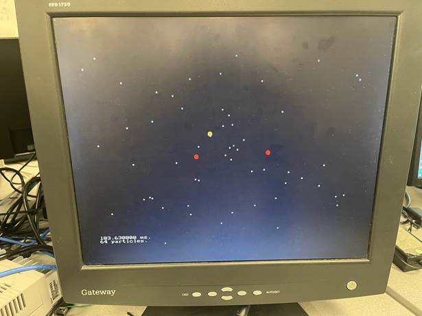
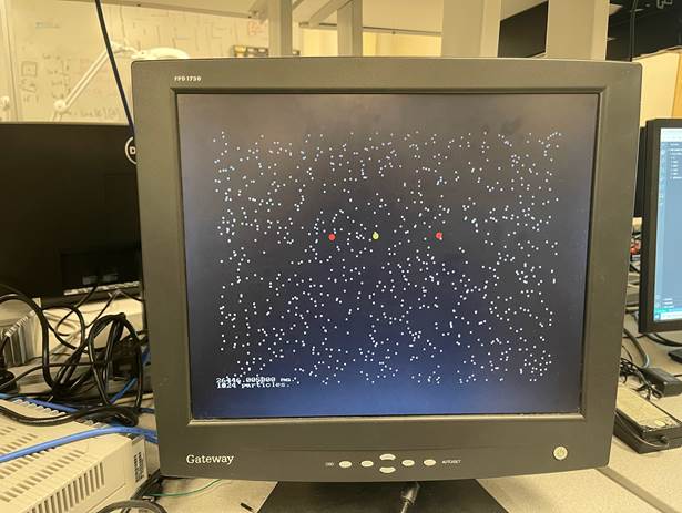
Figure 8:
VGA Display.
Testing
To test the functionality of the compute module, we utilized ModelSim, a simulation and verification tool. Since the hardware uses a 27-bit floating point, we modified the input and output ports to accommodate a 32-bit floating point for easy viewing and analysis in ModelSim. The testing process involved defining the initial conditions and comparing the calculated results with those obtained from a calculator to ensure the accuracy and correctness of the compute module.
Figure 9:
ModelSim Result.
Speed of Execution
|
Number of particles |
Frame Time[ms] |
|
16 |
6.6 |
|
32 |
26 |
|
64 |
103 |
|
72 |
130 |
|
128 |
413 |
|
1024 |
26446 |
Table 1: Frame Time vs. Number of
Particles Table.
Figure 10:
Frame Time vs. Number of Particles Chart.
To optimize the frame time, we attempted to incorporate as many compute modules as possible on the FPGA. Initially, we aimed to integrate 20 compute modules; however, we soon realized that this led to an exhaustion of logic elements on the hardware. Consequently, we had to reduce the number of compute modules to eight to fit within the available resources.
Accuracy
Since we used the 27-bit floating point on the FPGA side, we expect the accuracy to be smaller than that of the 32-bit floating point. Considering that we are dealing with large masses and distances, we could ignore the loss of accuracy because of the large magnitude of numbers we are dealing with.
Usability
Users can interact with the command line by following the action prompts displayed. They have several options available: they can either speed up or slow down the animation, achieved by adjusting the time step in integration. Additionally, they can choose to pause the animation. If users want to compare the relative speed and position of two specific particles, they can do so by entering the respective particle's ID numbers, which will then be highlighted within a circle. Users also have the ability to display the position, velocity, and mass of a selected particle. This is done by entering the particle's ID number, which will consequently be accentuated within a circle for easy viewing. All commands have text prompts, which are straightforward and easy to understand for the user.
Conclusions
To conclude, the development of the gravitational simulator was a successful endeavor, leading to a functional and user-friendly software tool that enables individuals to simulate and visualize gravitational interactions between objects. The project aimed to offer an educational and interactive platform for understanding the concepts of gravity and its impacts on celestial bodies, and it has achieved this objective.
Throughout the project, different components were designed and implemented, including the software architecture, the user interface, the gravitational compute module, and the visualization capabilities using the VGA display. These components were integrated perfectly to create a cohesive and robust gravitational simulator. We used the floating point calculation modules provided by previous groups who worked on a similar project. Our design is impossible without them. We also used Altera's VGA subsystem to implement the output to the display. We also used the SDRAM and SRAM on the SoC to accelerate the frame time to store the pixel color information. Although our design did not follow the GRAPE design, the GRAPE design proved to us that using FPGA to accelerate the gravitational simulation was possible.
The project's outcomes have shown the efficiency and functionality of the simulator. Users had the ability to easily interact with the software, simulate gravitational scenarios, and observe the resulting effects. Feedback from users suggested a high level of satisfaction with the software's performance, interface design, and user-friendly controls.
Furthermore, the project discovered optimizations to enhance the simulator's efficiency and accuracy. By executing efficient algorithms and leveraging hardware acceleration techniques, the simulator attained real-time simulation abilities despite a large number of objects.
While
the job was successful in meeting its goals, there are potential areas for
future improvement. This consists of expanding the simulator's abilities by
incorporating extra physics simulations and interactions, such as gravitational
slingshots and orbital mechanics. Additional improvements might also be made to
the visualization aspects, providing more advanced rendering methods and
customizable visual effects.
Appendix A: Permissions
The group approves this report for inclusion on the course website. The group approves the video for inclusion on the course youtube channel.
Appendix B: Work Distribution
Throughout the entire duration of the project, we ensured an equitable distribution of work. Although the following breakdown provides an approximate distribution, each member participated in all tasks.
|
Zilin Wang |
Haolin Li |
Yilu Zhou |
|
Gravitational module design |
Bus communication design |
VGA graph implementation |
|
HPS side C implementation |
HPS side C implementation |
HPS side C implementation |
|
FPGA and HPS debug |
FPGA and HPS debug |
FPGA and HPS debug |
Appendix C: References
[2] J. Makino, T. Fukushige, M. Koga, and K. Namura, “GRAPE-6: Massively-Parallel Special-Purpose Computer for Astrophysical Particle Simulations,” Publ. Astron. Soc. Jpn., vol. 55, no. 6, pp. 1163–1187, Dec. 2003, doi: 10.1093/pasj/55.6.1163.
Appendix D: Code Listing
VGA.c
// same obj1, different obj2 for all compute
modules
#include <fcntl.h>
#include <math.h>
#include <pthread.h>
#include <semaphore.h>
#include <stdbool.h>
#include <stdio.h>
#include <stdlib.h>
#include <string.h>
#include <sys/ipc.h>
#include <sys/mman.h>
#include <sys/shm.h>
#include <sys/time.h>
#include <sys/types.h>
#include <time.h>
#include <unistd.h>
#define particle_number 72
#define dt 10
#define scale 100
typedef struct object {
unsigned int number;
float mass;
float x_coord;
float y_coord;
float x_vel;
float y_vel;
unsigned int color;
unsigned int radius;
unsigned int old_display_x;
unsigned int old_display_y;
} particle;
// video display
#define SDRAM_BASE 0xC0000000
#define SDRAM_END 0xC3FFFFFF
#define SDRAM_SPAN 0x04000000
// characters
#define FPGA_CHAR_BASE 0xC9000000
#define FPGA_CHAR_END 0xC9001FFF
#define FPGA_CHAR_SPAN 0x00002000
/* Cyclone V FPGA devices */
#define HW_REGS_BASE 0xff200000
// #define HW_REGS_SPAN 0x00200000
#define HW_REGS_SPAN 0x00005000
// graphics primitives
void VGA_text(int, int, char *);
void VGA_text_clear();
void VGA_box(int, int, int, int, short);
void VGA_rect(int, int, int, int, short);
void VGA_line(int, int, int, int, short);
void VGA_Vline(int, int, int, short);
void VGA_Hline(int, int, int, short);
void VGA_disc(int, int, int, short);
void VGA_circle(int, int, int, int);
// 16-bit primary colors
#define red (0
+ (0
<< 5) + (31 << 11))
#define dark_red (0
+ (0
<< 5) + (15 << 11))
#define green (0
+ (63
<< 5) + (0 << 11))
#define dark_green (0
+ (31
<< 5) + (0 << 11))
#define blue (31
+ (0
<< 5) + (0 << 11))
#define dark_blue (15
+ (0
<< 5) + (0 << 11))
#define yellow (0
+ (63
<< 5) + (31 << 11))
#define cyan (31
+ (63
<< 5) + (0 << 11))
#define magenta (31
+ (0
<< 5) + (31 << 11))
#define black (0x0000)
#define gray (15
+ (31
<< 5) + (51 << 11))
#define white (0xffff)
int colors[]
= {red, dark_red, green, dark_green, blue,
dark_blue,
yellow, cyan, magenta, gray, black, white};
// pixel macro
#define VGA_PIXEL(x,
y, color) \
do {
\
int *pixel_ptr;
\
pixel_ptr = (int *)((char *)vga_pixel_ptr
+ (((y)*640 + (x)) << 1)); \
*(short *)pixel_ptr
= (color); \
} while (0)
// the light weight buss base
void *h2p_lw_virtual_base;
// pixel buffer
volatile unsigned int *vga_pixel_ptr = NULL;
void *vga_pixel_virtual_base;
// character buffer
volatile unsigned int *vga_char_ptr = NULL;
void *vga_char_virtual_base;
// /dev/mem file id
int fd;
// measure time
struct timeval t1, t2;
double elapsedTime;
// main bus; PIO
#define FPGA_AXI_BASE 0xC0000000
#define FPGA_AXI_SPAN 0x00001000
// main axi bus base
void *h2p_virtual_base;
volatile unsigned int *axi_pio_ptr = NULL;
volatile unsigned int *axi_pio_read_ptr = NULL;
// lw bus; PIO
#define FPGA_LW_BASE 0xff200000
#define FPGA_LW_SPAN 0x00001000
// HPS_to_FPGA FIFO status address = 0
volatile unsigned int *lw_pio_ptr = NULL;
volatile unsigned int *lw_pio_read_ptr = NULL;
unsigned int *obj_1_num_a =
NULL;
float *obj_1_mass_a = NULL;
float *obj_1_x_coord_a = NULL;
float *obj_1_y_coord_a = NULL;
unsigned int *obj_2_num_a0 =
NULL;
float *obj_2_mass_a0 = NULL;
float *obj_2_x_coord_a0 = NULL;
float *obj_2_y_coord_a0 = NULL;
volatile float *obj_1_delta_x_acc_b0 =
NULL;
volatile float *obj_1_delta_y_acc_b0 =
NULL;
volatile bool *complete0 =
NULL;
unsigned int *obj_2_num_a1 =
NULL;
float *obj_2_mass_a1 = NULL;
float *obj_2_x_coord_a1 = NULL;
float *obj_2_y_coord_a1 = NULL;
volatile float *obj_1_delta_x_acc_b1 =
NULL;
volatile float *obj_1_delta_y_acc_b1 =
NULL;
volatile bool *complete1 =
NULL;
unsigned int *obj_2_num_a2 =
NULL;
float *obj_2_mass_a2 = NULL;
float *obj_2_x_coord_a2 = NULL;
float *obj_2_y_coord_a2 = NULL;
volatile float *obj_1_delta_x_acc_b2 =
NULL;
volatile float *obj_1_delta_y_acc_b2 =
NULL;
volatile bool *complete2 =
NULL;
unsigned int *obj_2_num_a3 =
NULL;
float *obj_2_mass_a3 = NULL;
float *obj_2_x_coord_a3 = NULL;
float *obj_2_y_coord_a3 = NULL;
volatile float *obj_1_delta_x_acc_b3 =
NULL;
volatile float *obj_1_delta_y_acc_b3 =
NULL;
volatile bool *complete3 =
NULL;
unsigned int *obj_2_num_a4 =
NULL;
float *obj_2_mass_a4 = NULL;
float *obj_2_x_coord_a4 = NULL;
float *obj_2_y_coord_a4 = NULL;
volatile float *obj_1_delta_x_acc_b4 =
NULL;
volatile float *obj_1_delta_y_acc_b4 =
NULL;
volatile bool *complete4 =
NULL;
unsigned int *obj_2_num_a5 =
NULL;
float *obj_2_mass_a5 = NULL;
float *obj_2_x_coord_a5 = NULL;
float *obj_2_y_coord_a5 = NULL;
volatile float *obj_1_delta_x_acc_b5 =
NULL;
volatile float *obj_1_delta_y_acc_b5 =
NULL;
volatile bool *complete5 =
NULL;
unsigned int *obj_2_num_a6 =
NULL;
float *obj_2_mass_a6 = NULL;
float *obj_2_x_coord_a6 = NULL;
float *obj_2_y_coord_a6 = NULL;
volatile float *obj_1_delta_x_acc_b6 =
NULL;
volatile float *obj_1_delta_y_acc_b6 =
NULL;
volatile bool *complete6 =
NULL;
unsigned int *obj_2_num_a7 =
NULL;
float *obj_2_mass_a7 = NULL;
float *obj_2_x_coord_a7 = NULL;
float *obj_2_y_coord_a7 = NULL;
volatile float *obj_1_delta_x_acc_b7 =
NULL;
volatile float *obj_1_delta_y_acc_b7 =
NULL;
volatile bool *complete7 =
NULL;
bool *my_reset_ptr = NULL;
bool *data_sent_ptr = NULL;
// read offset is 0x10 for both busses
// remember that eaxh axi master bus needs unique
address
#define OBJ1_NUM_A 0x00
#define OBJ1_MASS_A 0x10
#define OBJ1_X_COORD_A 0x20
#define OBJ1_Y_COORD_A 0x30
#define COMPLETE0 0xa0
#define RESET 0xc0
#define OBJ2_NUM_A0 0x40
#define OBJ2_MASS_A0 0x50
#define OBJ2_X_COORD_A0 0x60
#define OBJ2_Y_COORD_A0 0x70
#define OBJ1_DELTA_X_ACC0 0x80
#define OBJ1_DELTA_Y_ACC0 0x90
#define OBJ2_NUM_A1 0x100
#define OBJ2_MASS_A1 0x110
#define OBJ2_X_COORD_A1 0x120
#define OBJ2_Y_COORD_A1 0x130
#define COMPLETE1 0x140
#define OBJ1_DELTA_X_ACC1 0x150
#define OBJ1_DELTA_Y_ACC1 0x160
#define OBJ2_NUM_A2 0x200
#define OBJ2_MASS_A2 0x210
#define OBJ2_X_COORD_A2 0x220
#define OBJ2_Y_COORD_A2 0x230
#define COMPLETE2 0x240
#define OBJ1_DELTA_X_ACC2 0x250
#define OBJ1_DELTA_Y_ACC2 0x260
#define OBJ2_NUM_A3 0x300
#define OBJ2_MASS_A3 0x310
#define OBJ2_X_COORD_A3 0x320
#define OBJ2_Y_COORD_A3 0x330
#define COMPLETE3 0x340
#define OBJ1_DELTA_X_ACC3 0x350
#define OBJ1_DELTA_Y_ACC3 0x360
#define OBJ2_NUM_A4 0x400
#define OBJ2_MASS_A4 0x410
#define OBJ2_X_COORD_A4 0x420
#define OBJ2_Y_COORD_A4 0x430
#define COMPLETE4 0x440
#define OBJ1_DELTA_X_ACC4 0x450
#define OBJ1_DELTA_Y_ACC4 0x460
#define OBJ2_NUM_A5 0x500
#define OBJ2_MASS_A5 0x510
#define OBJ2_X_COORD_A5 0x520
#define OBJ2_Y_COORD_A5 0x530
#define COMPLETE5 0x540
#define OBJ1_DELTA_X_ACC5 0x550
#define OBJ1_DELTA_Y_ACC5 0x560
#define OBJ2_NUM_A6 0x600
#define OBJ2_MASS_A6 0x610
#define OBJ2_X_COORD_A6 0x620
#define OBJ2_Y_COORD_A6 0x630
#define COMPLETE6 0x640
#define OBJ1_DELTA_X_ACC6 0x650
#define OBJ1_DELTA_Y_ACC6 0x660
#define OBJ2_NUM_A7 0x700
#define OBJ2_MASS_A7 0x710
#define OBJ2_X_COORD_A7 0x720
#define OBJ2_Y_COORD_A7 0x730
#define COMPLETE7 0x740
#define OBJ1_DELTA_X_ACC7 0x750
#define OBJ1_DELTA_Y_ACC7 0x760
#define DATA_SENT 0x800
int delta_t = dt;
int choice =
-1;
int go =
-1;
int particle_1 =
-1;
int particle_2 =
-1;
float x_rel_vel =
0;
float y_rel_vel =
0;
float x_rel_pos =
0;
float y_rel_pos =
0;
float particle_mass =
0;
float x_coord =
0;
float y_coord =
0;
float x_vel =
0;
float y_vel =
0;
particle *p_old;
particle *p_reset;
void *read1() {
while (1)
{
printf("Enter 1 to change speed, enter 2 for
relative speed, enter 3 for particle status:");
scanf("%d", &choice);
// flag = false;
int delta_t_old = 0;
switch (choice) {
case 1:
printf("Enter a value between 5 - 100 to change
speed: ");
scanf("%d", &delta_t);
break;
case 2:
delta_t_old =
delta_t;
delta_t = 0;
printf("Enter two particle number you want to
compare (between 0 and %d)\n", particle_number -
1);
printf("First particle:\n");
scanf("%d", &particle_1);
printf("Second particle:\n");
scanf("%d", &particle_2);
x_rel_pos = p_old[particle_1].x_coord - p_old[particle_2].x_coord;
y_rel_pos = p_old[particle_1].y_coord - p_old[particle_2].y_coord;
x_rel_vel = p_old[particle_1].x_vel - p_old[particle_2].x_vel;
y_rel_vel = p_old[particle_1].y_vel - p_old[particle_2].y_vel;
printf("X relative position is: %fm\n", x_rel_pos);
printf("Y relative position is: %fm\n", y_rel_pos);
printf("X relative velocity is: %fm/s\n", x_rel_vel);
printf("Y relative velocity is: %fm/s\n", y_rel_vel);
printf("Continue? (1 for yes, 2 for no)\n");
VGA_circle(p_old[particle_1].old_display_x, p_old[particle_1].old_display_y, 10, green);
VGA_circle(p_old[particle_2].old_display_x, p_old[particle_2].old_display_y, 10, green);
while (1) {
scanf("%d", &go);
if (go == 1) {
break;
}
}
VGA_circle(p_old[particle_1].old_display_x, p_old[particle_1].old_display_y, 10, black);
VGA_circle(p_old[particle_2].old_display_x, p_old[particle_2].old_display_y, 10, black);
delta_t = delta_t_old;
break;
case 3:
delta_t_old =
delta_t;
delta_t = 0;
printf("Enter the particle number you want to show
details (between 0 and %d):\n", particle_number -
1);
scanf("%d", &particle_1);
x_coord = p_old[particle_1].x_coord;
y_coord = p_old[particle_1].y_coord;
x_vel = p_old[particle_1].x_vel;
y_vel = p_old[particle_1].y_vel;
particle_mass =
p_old[particle_1].mass;
printf("mass is: %fkg\n", particle_mass);
printf("X position is: %fm\n", x_coord);
printf("Y position is: %fm\n", y_coord);
printf("X velocity is: %fm/s\n", x_vel);
printf("Y velocity is: %fm/s\n", y_vel);
printf("Continue? (1 for yes, 2 for no)\n");
VGA_circle(p_old[particle_1].old_display_x, p_old[particle_1].old_display_y, 10, yellow);
while (1) {
scanf("%d", &go);
if (go == 1) {
break;
}
}
VGA_circle(p_old[particle_1].old_display_x, p_old[particle_1].old_display_y, 10, black);
delta_t = delta_t_old;
break;
default:
break;
}
// flag = true;
}
}
int main(void) {
pthread_t thread_read;
// // For portability,
explicitly create threads in a joinable state
// // thread attribute
used here to allow JOIN
pthread_attr_t attr;
pthread_attr_init(&attr);
pthread_attr_setdetachstate(&attr, PTHREAD_CREATE_JOINABLE);
// thread
pthread_create(&thread_read, NULL, read1, NULL);
// === need to mmap:
=======================
// FPGA_CHAR_BASE
// FPGA_ONCHIP_BASE
// HW_REGS_BASE
// === get FPGA addresses
==================
// Open /dev/mem
if ((fd =
open("/dev/mem", (O_RDWR |
O_SYNC))) == -1)
{
printf("ERROR: could not open \"/dev/mem\"...\n");
return (1);
}
// get virtual addr that
maps to physical
h2p_lw_virtual_base =
mmap(NULL, HW_REGS_SPAN, (PROT_READ | PROT_WRITE), MAP_SHARED, fd, HW_REGS_BASE);
if (h2p_lw_virtual_base == MAP_FAILED) {
printf("ERROR: mmap1() failed...\n");
close(fd);
return (1);
}
// === get VGA char addr
=====================
// get virtual addr that
maps to physical
vga_char_virtual_base =
mmap(NULL, FPGA_CHAR_SPAN, (PROT_READ | PROT_WRITE), MAP_SHARED, fd, FPGA_CHAR_BASE);
if (vga_char_virtual_base == MAP_FAILED) {
printf("ERROR: mmap2() failed...\n");
close(fd);
return (1);
}
// Get the address that
maps to the FPGA LED control
vga_char_ptr =
(unsigned int *)(vga_char_virtual_base);
// === get VGA pixel addr
====================
// get virtual addr that
maps to physical
vga_pixel_virtual_base =
mmap(NULL, SDRAM_SPAN, (PROT_READ |
PROT_WRITE), MAP_SHARED, fd, SDRAM_BASE);
if (vga_pixel_virtual_base == MAP_FAILED) {
printf("ERROR: mmap3() failed...\n");
close(fd);
return (1);
}
// Get the address that
maps to the FPGA pixel buffer
vga_pixel_ptr =
(unsigned int *)(vga_pixel_virtual_base);
//
===========================================
// get virtual address for
// AXI bus addr
h2p_virtual_base =
mmap(NULL, FPGA_AXI_SPAN, (PROT_READ | PROT_WRITE), MAP_SHARED, fd, FPGA_AXI_BASE);
if (h2p_virtual_base == MAP_FAILED) {
printf("ERROR: mmap3() failed...\n");
close(fd);
return (1);
}
//============================================
// get virtual addr that
maps to physical
// for light weight AXI
bus
h2p_lw_virtual_base =
mmap(NULL, FPGA_LW_SPAN, (PROT_READ | PROT_WRITE), MAP_SHARED, fd, FPGA_LW_BASE);
if (h2p_lw_virtual_base == MAP_FAILED) {
printf("ERROR: mmap1() failed...\n");
close(fd);
return (1);
}
//============================================
// particle* p1 =
(particle*)calloc(1,sizeof(particle));
p_old = (particle *)calloc(particle_number, sizeof(particle));
p_reset = (particle *)calloc(particle_number, sizeof(particle));
obj_1_num_a =
(unsigned int *)(h2p_lw_virtual_base + OBJ1_NUM_A);
obj_1_mass_a =
(float *)(h2p_lw_virtual_base +
OBJ1_MASS_A);
obj_1_x_coord_a =
(float *)(h2p_lw_virtual_base +
OBJ1_X_COORD_A);
obj_1_y_coord_a =
(float *)(h2p_lw_virtual_base +
OBJ1_Y_COORD_A);
obj_2_num_a0 =
(unsigned int *)(h2p_lw_virtual_base + OBJ2_NUM_A0);
obj_2_mass_a0 =
(float *)(h2p_lw_virtual_base +
OBJ2_MASS_A0);
obj_2_x_coord_a0 =
(float *)(h2p_lw_virtual_base +
OBJ2_X_COORD_A0);
obj_2_y_coord_a0 = (float *)(h2p_lw_virtual_base +
OBJ2_Y_COORD_A0);
obj_1_delta_x_acc_b0 =
(float *)(h2p_lw_virtual_base +
OBJ1_DELTA_X_ACC0);
obj_1_delta_y_acc_b0 =
(float *)(h2p_lw_virtual_base +
OBJ1_DELTA_Y_ACC0);
complete0 = (bool *)(h2p_lw_virtual_base + COMPLETE0);
obj_2_num_a1 =
(unsigned int *)(h2p_lw_virtual_base + OBJ2_NUM_A1);
obj_2_mass_a1 =
(float *)(h2p_lw_virtual_base +
OBJ2_MASS_A1);
obj_2_x_coord_a1 =
(float *)(h2p_lw_virtual_base +
OBJ2_X_COORD_A1);
obj_2_y_coord_a1 =
(float *)(h2p_lw_virtual_base +
OBJ2_Y_COORD_A1);
obj_1_delta_x_acc_b1 =
(float *)(h2p_lw_virtual_base +
OBJ1_DELTA_X_ACC1);
obj_1_delta_y_acc_b1 =
(float *)(h2p_lw_virtual_base +
OBJ1_DELTA_Y_ACC1);
complete1 = (bool *)(h2p_lw_virtual_base + COMPLETE1);
obj_2_num_a2 =
(unsigned int *)(h2p_lw_virtual_base + OBJ2_NUM_A2);
obj_2_mass_a2 =
(float *)(h2p_lw_virtual_base +
OBJ2_MASS_A2);
obj_2_x_coord_a2 =
(float *)(h2p_lw_virtual_base +
OBJ2_X_COORD_A2);
obj_2_y_coord_a2 =
(float *)(h2p_lw_virtual_base +
OBJ2_Y_COORD_A2);
obj_1_delta_x_acc_b2 =
(float *)(h2p_lw_virtual_base +
OBJ1_DELTA_X_ACC2);
obj_1_delta_y_acc_b2 =
(float *)(h2p_lw_virtual_base +
OBJ1_DELTA_Y_ACC2);
complete2 = (bool *)(h2p_lw_virtual_base + COMPLETE2);
obj_2_num_a3 =
(unsigned int *)(h2p_lw_virtual_base + OBJ2_NUM_A3);
obj_2_mass_a3 =
(float *)(h2p_lw_virtual_base +
OBJ2_MASS_A3);
obj_2_x_coord_a3 =
(float *)(h2p_lw_virtual_base +
OBJ2_X_COORD_A3);
obj_2_y_coord_a3 =
(float *)(h2p_lw_virtual_base +
OBJ2_Y_COORD_A3);
obj_1_delta_x_acc_b3 =
(float *)(h2p_lw_virtual_base +
OBJ1_DELTA_X_ACC3);
obj_1_delta_y_acc_b3 =
(float *)(h2p_lw_virtual_base +
OBJ1_DELTA_Y_ACC3);
complete3 = (bool *)(h2p_lw_virtual_base + COMPLETE3);
obj_2_num_a4 =
(unsigned int *)(h2p_lw_virtual_base + OBJ2_NUM_A4);
obj_2_mass_a4 =
(float *)(h2p_lw_virtual_base +
OBJ2_MASS_A4);
obj_2_x_coord_a4 =
(float *)(h2p_lw_virtual_base +
OBJ2_X_COORD_A4);
obj_2_y_coord_a4 =
(float *)(h2p_lw_virtual_base +
OBJ2_Y_COORD_A4);
obj_1_delta_x_acc_b4 =
(float *)(h2p_lw_virtual_base +
OBJ1_DELTA_X_ACC4);
obj_1_delta_y_acc_b4 =
(float *)(h2p_lw_virtual_base +
OBJ1_DELTA_Y_ACC4);
complete4 = (bool *)(h2p_lw_virtual_base + COMPLETE4);
obj_2_num_a5 =
(unsigned int *)(h2p_lw_virtual_base + OBJ2_NUM_A5);
obj_2_mass_a5 = (float *)(h2p_lw_virtual_base +
OBJ2_MASS_A5);
obj_2_x_coord_a5 =
(float *)(h2p_lw_virtual_base +
OBJ2_X_COORD_A5);
obj_2_y_coord_a5 =
(float *)(h2p_lw_virtual_base +
OBJ2_Y_COORD_A5);
obj_1_delta_x_acc_b5 =
(float *)(h2p_lw_virtual_base +
OBJ1_DELTA_X_ACC5);
obj_1_delta_y_acc_b5 =
(float *)(h2p_lw_virtual_base +
OBJ1_DELTA_Y_ACC5);
complete5 = (bool *)(h2p_lw_virtual_base + COMPLETE5);
obj_2_num_a6 =
(unsigned int *)(h2p_lw_virtual_base + OBJ2_NUM_A6);
obj_2_mass_a6 =
(float *)(h2p_lw_virtual_base +
OBJ2_MASS_A6);
obj_2_x_coord_a6 =
(float *)(h2p_lw_virtual_base +
OBJ2_X_COORD_A6);
obj_2_y_coord_a6 =
(float *)(h2p_lw_virtual_base +
OBJ2_Y_COORD_A6);
obj_1_delta_x_acc_b6 =
(float *)(h2p_lw_virtual_base +
OBJ1_DELTA_X_ACC6);
obj_1_delta_y_acc_b6 =
(float *)(h2p_lw_virtual_base +
OBJ1_DELTA_Y_ACC6);
complete6 = (bool *)(h2p_lw_virtual_base + COMPLETE6);
obj_2_num_a7 =
(unsigned int *)(h2p_lw_virtual_base + OBJ2_NUM_A7);
obj_2_mass_a7 =
(float *)(h2p_lw_virtual_base +
OBJ2_MASS_A7);
obj_2_x_coord_a7 =
(float *)(h2p_lw_virtual_base +
OBJ2_X_COORD_A7);
obj_2_y_coord_a7 =
(float *)(h2p_lw_virtual_base +
OBJ2_Y_COORD_A7);
obj_1_delta_x_acc_b7 =
(float *)(h2p_lw_virtual_base +
OBJ1_DELTA_X_ACC7);
obj_1_delta_y_acc_b7 =
(float *)(h2p_lw_virtual_base +
OBJ1_DELTA_Y_ACC7);
complete7 = (bool *)(h2p_lw_virtual_base + COMPLETE7);
my_reset_ptr =
(bool *)(h2p_lw_virtual_base +
RESET);
data_sent_ptr =
(bool *)(h2p_lw_virtual_base +
DATA_SENT);
struct timespec req, rem;
req.tv_sec = 0;
req.tv_nsec = 1;
int i =
0;
int j =
0;
struct timeval t1, t2;
double elapsedTime;
int k =
0;
// init
p_old[0].number = 0;
p_old[0].mass =
8000000000000000;
p_old[0].x_coord = 30000;
p_old[0].y_coord = 20000;
p_old[0].x_vel =
0;
p_old[0].y_vel =
0;
p_old[0].color =
yellow;
p_old[0].radius = 4;
p_old[0].old_display_x = p_old[0].x_coord / scale;
p_old[0].old_display_y = p_old[0].y_coord / scale;
p_old[1].number = 1;
p_old[1].mass =
2000000000000000;
p_old[1].x_coord = 30000 - 7000;
p_old[1].y_coord = 20000;
p_old[1].x_vel =
-3.25;
p_old[1].y_vel =
6;
p_old[1].color =
red;
p_old[1].radius = 4;
p_old[1].old_display_x = p_old[1].x_coord / scale;
p_old[1].old_display_y = p_old[1].y_coord / scale;
p_old[2].number = 2;
p_old[2].mass =
90000000000000;
p_old[2].x_coord = 30000 + 10000;
p_old[2].y_coord = 20000;
p_old[2].x_vel =
3.25;
p_old[2].y_vel =
4;
p_old[2].color =
red;
p_old[2].radius = 4;
p_old[2].old_display_x = p_old[2].x_coord / scale;
p_old[2].old_display_y = p_old[2].y_coord / scale;
for (k =
3; k < particle_number; k++)
{
p_old[k].number = k;
p_old[k].mass = random_range(100000, 1000000000);
p_old[k].x_coord = random_range(50 * 100, 589 * 100);
p_old[k].y_coord = random_range(50 * 100, 429 * 100);
p_old[k].x_vel = random_range(0, 6) - 3;
p_old[k].y_vel = random_range(0, 4) - 2;
p_old[k].color = white;
p_old[k].radius = 1;
p_old[k].old_display_x = p_old[k].x_coord / scale;
p_old[k].old_display_y = p_old[k].y_coord / scale;
}
memcpy(p_reset, p_old,
particle_number * sizeof(particle));
particle
*p_new;
VGA_box(0, 0, 639, 479, black);
char screen_text[32];
while (1)
{
p_new = (particle *)calloc(particle_number, sizeof(particle));
memcpy(p_new, p_old,
particle_number * sizeof(particle));
gettimeofday(&t1, NULL);
for (i =
0; i < particle_number; i++)
{
*obj_1_num_a =
p_old[i].number;
*obj_1_mass_a = p_old[i].mass;
*obj_1_x_coord_a = p_old[i].x_coord;
*obj_1_y_coord_a = p_old[i].y_coord;
int j =
0;
float obj_1_sum_x_acc = 0;
float obj_1_sum_y_acc = 0;
while (j < particle_number) {
*obj_2_num_a0 = p_old[j].number;
*obj_2_mass_a0 = p_old[j].mass;
*obj_2_x_coord_a0 = p_old[j].x_coord;
*obj_2_y_coord_a0 = p_old[j].y_coord;
j++;
*obj_2_num_a1 = p_old[j].number;
*obj_2_mass_a1 = p_old[j].mass;
*obj_2_x_coord_a1 = p_old[j].x_coord;
*obj_2_y_coord_a1 = p_old[j].y_coord;
j++;
*obj_2_num_a2 = p_old[j].number;
*obj_2_mass_a2 = p_old[j].mass;
*obj_2_x_coord_a2 = p_old[j].x_coord;
*obj_2_y_coord_a2 = p_old[j].y_coord;
j++;
*obj_2_num_a3 = p_old[j].number;
*obj_2_mass_a3 = p_old[j].mass;
*obj_2_x_coord_a3 = p_old[j].x_coord;
*obj_2_y_coord_a3 = p_old[j].y_coord;
j++;
*obj_2_num_a4 = p_old[j].number;
*obj_2_mass_a4 = p_old[j].mass;
*obj_2_x_coord_a4 = p_old[j].x_coord;
*obj_2_y_coord_a4 = p_old[j].y_coord;
j++;
*obj_2_num_a5 = p_old[j].number;
*obj_2_mass_a5 = p_old[j].mass;
*obj_2_x_coord_a5 = p_old[j].x_coord;
*obj_2_y_coord_a5 = p_old[j].y_coord;
j++;
*obj_2_num_a6 = p_old[j].number;
*obj_2_mass_a6 = p_old[j].mass;
*obj_2_x_coord_a6 = p_old[j].x_coord;
*obj_2_y_coord_a6 = p_old[j].y_coord;
j++;
*obj_2_num_a7 = p_old[j].number;
*obj_2_mass_a7 = p_old[j].mass;
*obj_2_x_coord_a7 = p_old[j].x_coord;
*obj_2_y_coord_a7 = p_old[j].y_coord;
j++;
*my_reset_ptr = false;
usleep(2);
*my_reset_ptr = true;
usleep(2);
*my_reset_ptr = false;
usleep(2);
while (!(*complete0))
;
//
calculate net acceleration
obj_1_sum_x_acc +=
+*obj_1_delta_x_acc_b0 + *obj_1_delta_x_acc_b1 + *obj_1_delta_x_acc_b2
+ *obj_1_delta_x_acc_b3
+ *obj_1_delta_x_acc_b4
+ *obj_1_delta_x_acc_b5
+ *obj_1_delta_x_acc_b6
+ *obj_1_delta_x_acc_b7;
obj_1_sum_y_acc +=
*obj_1_delta_y_acc_b0 + *obj_1_delta_y_acc_b1 + *obj_1_delta_y_acc_b2
+ *obj_1_delta_y_acc_b3
+ *obj_1_delta_y_acc_b4
+ *obj_1_delta_y_acc_b5
+ *obj_1_delta_y_acc_b6
+ *obj_1_delta_y_acc_b7;
}
float obj_1_new_x_vel = p_old[i].x_vel + obj_1_sum_x_acc * delta_t;
float obj_1_new_y_vel = p_old[i].y_vel + obj_1_sum_y_acc * delta_t;
float obj_1_new_x_coord = p_old[i].x_coord + obj_1_new_x_vel * delta_t;
float obj_1_new_y_coord = p_old[i].y_coord + obj_1_new_y_vel * delta_t;
int obj_1_new_display_x = (obj_1_new_x_coord < 0) ? 0 : (obj_1_new_x_coord > 639) ? 639
: (int)obj_1_new_x_coord;
int obj_1_new_display_y = (obj_1_new_y_coord < 0) ? 0 : (obj_1_new_y_coord > 479) ? 479
: (int)obj_1_new_y_coord;
int obj_1_old_display_x = (p_old[i].x_coord < 0) ? 0 : (p_old[i].x_coord > 639) ? 639
: (int)p_old[i].x_coord;
int obj_1_old_display_y = (p_old[i].y_coord < 0) ? 0 : (p_old[i].y_coord > 479) ? 479
: (int)p_old[i].y_coord;
p_new[i].x_coord = obj_1_new_x_coord;
p_new[i].y_coord = obj_1_new_y_coord;
p_new[i].x_vel = obj_1_new_x_vel;
p_new[i].y_vel = obj_1_new_y_vel;
p_new[i].old_display_x = p_new[i].x_coord / scale;
p_new[i].old_display_y = p_new[i].y_coord / scale;
VGA_disc(p_old[i].old_display_x, p_old[i].old_display_y, p_old[i].radius, black); // remove old
VGA_disc(p_new[i].old_display_x, p_new[i].old_display_y, p_old[i].radius, p_old[i].color); // add new
}
gettimeofday(&t2, NULL);
elapsedTime =
(t2.tv_sec - t1.tv_sec) * 1000.0; // sec
to ms
elapsedTime +=
(t2.tv_usec - t1.tv_usec) / 1000.0; // us to
ms
VGA_text_clear();
sprintf(screen_text, "%f ms.", elapsedTime);
VGA_text(5, 52, screen_text);
sprintf(screen_text, "%d particles.", particle_number);
VGA_text(5, 53, screen_text);
// delete old memory
free(p_old);
p_old = p_new;
}
} // end main
/**************************************************************************************
* Random
number within range (upper,lower)
**************************************************************************************/
int random_range(int lower, int upper) {
int num =
(rand() %
(upper - lower + 1))
+
lower;
return num;
}
/****************************************************************************************
*
Subroutine to send a string of text to the VGA monitor
****************************************************************************************/
void VGA_text(int x, int y, char *text_ptr) {
volatile char *character_buffer = (char *)vga_char_ptr; // VGA character buffer
int offset;
/*
assume that the text string fits on one line */
offset = (y << 7) + x;
while (*(text_ptr))
{
// write to the character
buffer
*(character_buffer + offset) =
*(text_ptr);
++text_ptr;
++offset;
}
}
/****************************************************************************************
*
Subroutine to clear text to the VGA monitor
****************************************************************************************/
void VGA_text_clear() {
volatile char *character_buffer = (char *)vga_char_ptr; // VGA character buffer
int offset, x, y;
for (x =
0; x < 79; x++) {
for (y =
0; y < 59; y++) {
/* assume that the text string fits on one line */
offset = (y << 7) + x;
// write to the character
buffer
*(character_buffer + offset) =
' ';
}
}
}
/****************************************************************************************
* Draw a
filled rectangle on the VGA monitor
****************************************************************************************/
#define SWAP(X,
Y) \
do {
\
int
temp = X; \
X = Y; \
Y = temp; \
} while (0)
void VGA_box(int x1, int y1, int x2, int y2, short pixel_color) {
char *pixel_ptr;
int row, col;
/* check
and fix box coordinates to be valid */
if (x1 > 639)
x1 = 639;
if (y1 > 479)
y1 = 479;
if (x2 > 639)
x2 = 639;
if (y2 > 479)
y2 = 479;
if (x1 < 0)
x1 = 0;
if (y1 < 0)
y1 = 0;
if (x2 < 0)
x2 = 0;
if (y2 < 0)
y2 = 0;
if (x1 > x2)
SWAP(x1, x2);
if (y1 > y2)
SWAP(y1, y2);
for (row =
y1; row <= y2; row++)
for (col =
x1; col <= x2; ++col) {
// 640x480
// pixel_ptr = (char
*)vga_pixel_ptr + (row<<10) +
col ;
// set pixel color
//*(char *)pixel_ptr =
pixel_color;
VGA_PIXEL(col, row, pixel_color);
}
}
/****************************************************************************************
* Draw a
outline rectangle on the VGA monitor
****************************************************************************************/
#define SWAP(X,
Y) \
do {
\
int
temp = X; \
X = Y; \
Y = temp; \
} while (0)
void VGA_rect(int x1, int y1, int x2, int y2, short pixel_color) {
char *pixel_ptr;
int row, col;
/* check
and fix box coordinates to be valid */
if (x1 > 639)
x1 = 639;
if (y1 > 479)
y1 = 479;
if (x2 > 639)
x2 = 639;
if (y2 > 479)
y2 = 479;
if (x1 < 0)
x1 = 0;
if (y1 < 0)
y1 = 0;
if (x2 < 0)
x2 = 0;
if (y2 < 0)
y2 = 0;
if (x1 > x2)
SWAP(x1, x2);
if (y1 > y2)
SWAP(y1, y2);
// left edge
col = x1;
for (row =
y1; row <= y2; row++) {
// 640x480
// pixel_ptr = (char
*)vga_pixel_ptr + (row<<10) +
col ;
// set pixel color
//*(char *)pixel_ptr =
pixel_color;
VGA_PIXEL(col, row, pixel_color);
}
// right edge
col = x2;
for (row =
y1; row <= y2; row++) {
// 640x480
// pixel_ptr = (char
*)vga_pixel_ptr + (row<<10) +
col ;
// set pixel color
//*(char *)pixel_ptr =
pixel_color;
VGA_PIXEL(col, row, pixel_color);
}
// top edge
row = y1;
for (col =
x1; col <= x2; ++col) {
// 640x480
// pixel_ptr = (char
*)vga_pixel_ptr + (row<<10) +
col ;
// set pixel color
//*(char *)pixel_ptr =
pixel_color;
VGA_PIXEL(col, row, pixel_color);
}
// bottom edge
row = y2;
for (col =
x1; col <= x2; ++col) {
// 640x480
// pixel_ptr = (char
*)vga_pixel_ptr + (row<<10) +
col ;
// set pixel color
//*(char *)pixel_ptr =
pixel_color;
VGA_PIXEL(col, row, pixel_color);
}
}
/****************************************************************************************
* Draw a
horixontal line on the VGA monitor
****************************************************************************************/
#define SWAP(X,
Y) \
do {
\
int
temp = X; \
X = Y; \
Y = temp; \
} while (0)
void VGA_Hline(int x1, int y1, int x2, short pixel_color) {
char *pixel_ptr;
int row, col;
/* check
and fix box coordinates to be valid */
if (x1 > 639)
x1 = 639;
if (y1 > 479)
y1 = 479;
if (x2 > 639)
x2 = 639;
if (x1 < 0)
x1 = 0;
if (y1 < 0)
y1 = 0;
if (x2 < 0)
x2 = 0;
if (x1 > x2)
SWAP(x1, x2);
// line
row = y1;
for (col =
x1; col <= x2; ++col) {
// 640x480
// pixel_ptr = (char
*)vga_pixel_ptr + (row<<10) +
col ;
// set pixel color
//*(char *)pixel_ptr =
pixel_color;
VGA_PIXEL(col, row, pixel_color);
}
}
/****************************************************************************************
* Draw a
vertical line on the VGA monitor
****************************************************************************************/
#define SWAP(X,
Y) \
do {
\
int
temp = X; \
X = Y; \
Y = temp; \
} while (0)
void VGA_Vline(int x1, int y1, int y2, short pixel_color) {
char *pixel_ptr;
int row, col;
/* check
and fix box coordinates to be valid */
if (x1 > 639)
x1 = 639;
if (y1 > 479)
y1 = 479;
if (y2 > 479)
y2 = 479;
if (x1 < 0)
x1 = 0;
if (y1 < 0)
y1 = 0;
if (y2 < 0)
y2 = 0;
if (y1 > y2)
SWAP(y1, y2);
// line
col = x1;
for (row =
y1; row <= y2; row++) {
// 640x480
// pixel_ptr = (char
*)vga_pixel_ptr + (row<<10) +
col ;
// set pixel color
//*(char *)pixel_ptr =
pixel_color;
VGA_PIXEL(col, row, pixel_color);
}
}
/****************************************************************************************
* Draw a
filled circle on the VGA monitor
****************************************************************************************/
void VGA_disc(int x, int y, int r, short pixel_color) {
char *pixel_ptr;
int row, col, rsqr, xc, yc;
rsqr = r *
r;
for (yc =
-r; yc <= r; yc++)
for (xc =
-r; xc <= r; xc++)
{
col = xc;
row = yc;
// add the r to make the
edge smoother
if (col *
col + row * row <= rsqr +
r) {
col += x; // add the
center point
row += y; // add the
center point
//
check for valid 640x480
if (col > 639)
col = 639;
if (row > 479)
row = 479;
if (col < 0)
col = 0;
if (row < 0)
row = 0;
//
pixel_ptr = (char *)vga_pixel_ptr + (row<<10) + col ;
// set pixel color
//*(char
*)pixel_ptr = pixel_color;
VGA_PIXEL(col, row, pixel_color);
}
}
}
/****************************************************************************************
* Draw
a circle on the VGA monitor
****************************************************************************************/
void VGA_circle(int x, int y, int r, int pixel_color) {
char *pixel_ptr;
int row, col, rsqr, xc, yc;
int col1, row1;
rsqr = r *
r;
for (yc =
-r; yc <= r; yc++)
{
// row = yc;
col1
= (int)sqrt((float)(rsqr +
r - yc * yc));
// right edge
col = col1 +
x; // add the center point
row = yc +
y; // add the center point
// check for valid 640x480
if (col > 639)
col = 639;
if (row > 479)
row = 479;
if (col < 0)
col = 0;
if (row < 0)
row = 0;
// pixel_ptr = (char
*)vga_pixel_ptr + (row<<10) + col ;
// set pixel color
//*(char *)pixel_ptr =
pixel_color;
VGA_PIXEL(col, row, pixel_color);
// left edge
col = -col1
+ x; // add the center point
// check for valid 640x480
if (col > 639)
col = 639;
if (row > 479)
row = 479;
if (col < 0)
col = 0;
if (row < 0)
row = 0;
// pixel_ptr = (char
*)vga_pixel_ptr + (row<<10) + col ;
// set pixel color
//*(char *)pixel_ptr =
pixel_color;
VGA_PIXEL(col, row, pixel_color);
}
for (xc =
-r; xc <= r; xc++)
{
// row = yc;
row1
= (int)sqrt((float)(rsqr +
r - xc * xc));
// right edge
col = xc +
x; // add the center point
row = row1 +
y; // add the center point
// check for valid 640x480
if (col > 639)
col = 639;
if (row > 479)
row = 479;
if (col < 0)
col = 0;
if (row < 0)
row = 0;
// pixel_ptr = (char
*)vga_pixel_ptr + (row<<10) + col ;
// set pixel color
//*(char *)pixel_ptr =
pixel_color;
VGA_PIXEL(col, row, pixel_color);
// left edge
row = -row1
+ y; // add the center point
// check for valid 640x480
if (col > 639)
col = 639;
if (row > 479)
row = 479;
if (col < 0)
col = 0;
if (row < 0)
row = 0;
// pixel_ptr = (char
*)vga_pixel_ptr + (row<<10) + col ;
// set pixel color
//*(char *)pixel_ptr =
pixel_color;
VGA_PIXEL(col, row, pixel_color);
}
}
// =============================================
// === Draw a line
// =============================================
// plot a line
// at x1,y1 to x2,y2 with color
// Code is from David Rodgers,
//"Procedural Elements of Computer
Graphics",1985
void VGA_line(int x1, int y1, int x2, int y2, short c) {
int e;
signed int dx, dy, j, temp;
signed int s1, s2, xchange;
signed int x, y;
char *pixel_ptr;
/* check
and fix line coordinates to be valid */
if (x1 > 639)
x1 = 639;
if (y1 > 479)
y1 = 479;
if (x2 > 639)
x2 = 639;
if (y2 > 479)
y2 = 479;
if (x1 < 0)
x1 = 0;
if (y1 < 0)
y1 = 0;
if (x2 < 0)
x2 = 0;
if (y2 < 0)
y2 = 0;
x = x1;
y = y1;
// take absolute value
if (x2 < x1) {
dx = x1 -
x2;
s1 = -1;
}
else if
(x2 == x1) {
dx = 0;
s1 = 0;
}
else {
dx = x2 -
x1;
s1 = 1;
}
if (y2 < y1) {
dy = y1 -
y2;
s2 = -1;
}
else if
(y2 == y1) {
dy = 0;
s2 = 0;
}
else {
dy = y2 -
y1;
s2 = 1;
}
xchange = 0;
if (dy > dx) {
temp
= dx;
dx = dy;
dy = temp;
xchange = 1;
}
e = ((int)dy << 1) - dx;
for (j =
0; j <= dx; j++)
{
// video_pt(x,y,c);
//640x480
// pixel_ptr = (char
*)vga_pixel_ptr + (y<<10)+ x;
// set pixel color
//*(char *)pixel_ptr = c;
VGA_PIXEL(x, y, c);
if (e >= 0) {
if (xchange ==
1)
x = x + s1;
else
y = y + s2;
e = e - ((int)dx << 1);
}
if (xchange ==
1)
y = y + s2;
else
x = x + s1;
e = e +
((int)dy << 1);
}
}
DE1-SoC-Computer
module DE1_SoC_Computer (
////////////////////////////////////
// FPGA Pins
////////////////////////////////////
// Clock pins
CLOCK_50,
CLOCK2_50,
CLOCK3_50,
CLOCK4_50,
// ADC
ADC_CS_N,
ADC_DIN,
ADC_DOUT,
ADC_SCLK,
// Audio
AUD_ADCDAT,
AUD_ADCLRCK,
AUD_BCLK,
AUD_DACDAT,
AUD_DACLRCK,
AUD_XCK,
// SDRAM
DRAM_ADDR,
DRAM_BA,
DRAM_CAS_N,
DRAM_CKE,
DRAM_CLK,
DRAM_CS_N,
DRAM_DQ,
DRAM_LDQM,
DRAM_RAS_N,
DRAM_UDQM,
DRAM_WE_N,
// I2C Bus for
Configuration of the Audio and Video-In Chips
FPGA_I2C_SCLK,
FPGA_I2C_SDAT,
// 40-Pin Headers
GPIO_0,
GPIO_1,
// Seven Segment Displays
HEX0,
HEX1,
HEX2,
HEX3,
HEX4,
HEX5,
// IR
IRDA_RXD,
IRDA_TXD,
// Pushbuttons
KEY,
// LEDs
LEDR,
// PS2 Ports
PS2_CLK,
PS2_DAT,
PS2_CLK2,
PS2_DAT2,
// Slider Switches
SW,
// Video-In
TD_CLK27,
TD_DATA,
TD_HS,
TD_RESET_N,
TD_VS,
// VGA
VGA_B,
VGA_BLANK_N,
VGA_CLK,
VGA_G,
VGA_HS,
VGA_R,
VGA_SYNC_N,
VGA_VS,
////////////////////////////////////
// HPS Pins
////////////////////////////////////
// DDR3 SDRAM
HPS_DDR3_ADDR,
HPS_DDR3_BA,
HPS_DDR3_CAS_N,
HPS_DDR3_CKE,
HPS_DDR3_CK_N,
HPS_DDR3_CK_P,
HPS_DDR3_CS_N,
HPS_DDR3_DM,
HPS_DDR3_DQ,
HPS_DDR3_DQS_N,
HPS_DDR3_DQS_P,
HPS_DDR3_ODT,
HPS_DDR3_RAS_N,
HPS_DDR3_RESET_N,
HPS_DDR3_RZQ,
HPS_DDR3_WE_N,
// Ethernet
HPS_ENET_GTX_CLK,
HPS_ENET_INT_N,
HPS_ENET_MDC,
HPS_ENET_MDIO,
HPS_ENET_RX_CLK,
HPS_ENET_RX_DATA,
HPS_ENET_RX_DV,
HPS_ENET_TX_DATA,
HPS_ENET_TX_EN,
// Flash
HPS_FLASH_DATA,
HPS_FLASH_DCLK,
HPS_FLASH_NCSO,
// Accelerometer
HPS_GSENSOR_INT,
// General Purpose I/O
HPS_GPIO,
// I2C
HPS_I2C_CONTROL,
HPS_I2C1_SCLK,
HPS_I2C1_SDAT,
HPS_I2C2_SCLK,
HPS_I2C2_SDAT,
// Pushbutton
HPS_KEY,
// LED
HPS_LED,
// SD Card
HPS_SD_CLK,
HPS_SD_CMD,
HPS_SD_DATA,
// SPI
HPS_SPIM_CLK,
HPS_SPIM_MISO,
HPS_SPIM_MOSI,
HPS_SPIM_SS,
// UART
HPS_UART_RX,
HPS_UART_TX,
// USB
HPS_CONV_USB_N,
HPS_USB_CLKOUT,
HPS_USB_DATA,
HPS_USB_DIR,
HPS_USB_NXT,
HPS_USB_STP
);
//=======================================================
//
PARAMETER declarations
//=======================================================
//=======================================================
// PORT
declarations
//=======================================================
////////////////////////////////////
// FPGA Pins
////////////////////////////////////
// Clock pins
input
CLOCK_50;
input
CLOCK2_50;
input
CLOCK3_50;
input
CLOCK4_50;
// ADC
inout
ADC_CS_N;
output ADC_DIN;
input
ADC_DOUT;
output
ADC_SCLK;
// Audio
input
AUD_ADCDAT;
inout
AUD_ADCLRCK;
inout
AUD_BCLK;
output
AUD_DACDAT;
inout AUD_DACLRCK;
output AUD_XCK;
// SDRAM
output [12: 0]
DRAM_ADDR;
output [ 1: 0]
DRAM_BA;
output
DRAM_CAS_N;
output
DRAM_CKE;
output
DRAM_CLK;
output
DRAM_CS_N;
inout [15: 0]
DRAM_DQ;
output
DRAM_LDQM;
output
DRAM_RAS_N;
output
DRAM_UDQM;
output
DRAM_WE_N;
// I2C Bus for Configuration of the Audio and
Video-In Chips
output
FPGA_I2C_SCLK;
inout
FPGA_I2C_SDAT;
// 40-pin headers
inout [35: 0]
GPIO_0;
inout [35: 0]
GPIO_1;
// Seven Segment Displays
output [ 6: 0]
HEX0;
output [ 6: 0]
HEX1;
output [ 6: 0]
HEX2;
output [ 6: 0]
HEX3;
output [ 6: 0]
HEX4;
output [ 6: 0]
HEX5;
// IR
input
IRDA_RXD;
output
IRDA_TXD;
// Pushbuttons
input [ 3: 0]
KEY;
// LEDs
output [ 9: 0]
LEDR;
// PS2 Ports
inout
PS2_CLK;
inout
PS2_DAT;
inout
PS2_CLK2;
inout
PS2_DAT2;
// Slider Switches
input [ 9: 0]
SW;
// Video-In
input
TD_CLK27;
input [ 7: 0]
TD_DATA;
input
TD_HS;
output
TD_RESET_N;
input
TD_VS;
// VGA
output [ 7: 0]
VGA_B;
output
VGA_BLANK_N;
output VGA_CLK;
output [ 7: 0]
VGA_G;
output VGA_HS;
output [ 7: 0]
VGA_R;
output
VGA_SYNC_N;
output VGA_VS;
////////////////////////////////////
// HPS Pins
////////////////////////////////////
// DDR3 SDRAM
output [14: 0]
HPS_DDR3_ADDR;
output [ 2: 0] HPS_DDR3_BA;
output
HPS_DDR3_CAS_N;
output
HPS_DDR3_CKE;
output
HPS_DDR3_CK_N;
output
HPS_DDR3_CK_P;
output
HPS_DDR3_CS_N;
output [ 3: 0]
HPS_DDR3_DM;
inout [31: 0]
HPS_DDR3_DQ;
inout [ 3: 0]
HPS_DDR3_DQS_N;
inout [ 3: 0]
HPS_DDR3_DQS_P;
output
HPS_DDR3_ODT;
output
HPS_DDR3_RAS_N;
output HPS_DDR3_RESET_N;
input
HPS_DDR3_RZQ;
output
HPS_DDR3_WE_N;
// Ethernet
output
HPS_ENET_GTX_CLK;
inout
HPS_ENET_INT_N;
output
HPS_ENET_MDC;
inout
HPS_ENET_MDIO;
input
HPS_ENET_RX_CLK;
input [ 3: 0]
HPS_ENET_RX_DATA;
input
HPS_ENET_RX_DV;
output [ 3: 0]
HPS_ENET_TX_DATA;
output
HPS_ENET_TX_EN;
// Flash
inout [ 3: 0]
HPS_FLASH_DATA;
output
HPS_FLASH_DCLK;
output
HPS_FLASH_NCSO;
// Accelerometer
inout
HPS_GSENSOR_INT;
// General Purpose I/O
inout [ 1: 0]
HPS_GPIO;
// I2C
inout
HPS_I2C_CONTROL;
inout
HPS_I2C1_SCLK;
inout
HPS_I2C1_SDAT;
inout
HPS_I2C2_SCLK;
inout
HPS_I2C2_SDAT;
// Pushbutton
inout
HPS_KEY;
// LED
inout
HPS_LED;
// SD Card
output
HPS_SD_CLK;
inout
HPS_SD_CMD;
inout [ 3: 0]
HPS_SD_DATA;
// SPI
output
HPS_SPIM_CLK;
input
HPS_SPIM_MISO;
output
HPS_SPIM_MOSI;
inout
HPS_SPIM_SS;
// UART
input
HPS_UART_RX;
output
HPS_UART_TX;
// USB
inout
HPS_CONV_USB_N;
input
HPS_USB_CLKOUT;
inout [ 7: 0]
HPS_USB_DATA;
input
HPS_USB_DIR;
input HPS_USB_NXT;
output
HPS_USB_STP;
//=======================================================
// REG/WIRE
declarations
//=======================================================
wire [15: 0]
hex3_hex0;
//wire
[15: 0] hex5_hex4;
//assign HEX0 = ~hex3_hex0[ 6: 0]; // hex3_hex0[
6: 0];
//assign HEX1 = ~hex3_hex0[14: 8];
//assign HEX2 = ~hex3_hex0[22:16];
//assign HEX3 = ~hex3_hex0[30:24];
assign HEX4 =
7'b1111111;
assign HEX5 =
7'b1111111;
// HexDigit Digit0(HEX0, hex3_hex0[3:0]);
// HexDigit Digit1(HEX1, hex3_hex0[7:4]);
// HexDigit Digit2(HEX2, hex3_hex0[11:8]);
// HexDigit Digit3(HEX3, hex3_hex0[15:12]);
//=======================================================
//
Structural coding
//=======================================================
Computer_System The_System (
////////////////////////////////////
// FPGA Side
////////////////////////////////////
// Global signals
.system_pll_ref_clk_clk
(CLOCK_50),
.system_pll_ref_reset_reset
(1'b0),
// AV Config
.av_config_SCLK
(FPGA_I2C_SCLK),
.av_config_SDAT
(FPGA_I2C_SDAT),
// VGA Subsystem
.vga_pll_ref_clk_clk
(CLOCK2_50),
.vga_pll_ref_reset_reset
(1'b0),
.vga_CLK
(VGA_CLK),
.vga_BLANK
(VGA_BLANK_N),
.vga_SYNC
(VGA_SYNC_N),
.vga_HS (VGA_HS),
.vga_VS (VGA_VS),
.vga_R (VGA_R),
.vga_G (VGA_G),
.vga_B (VGA_B),
// SDRAM
.sdram_clk_clk (DRAM_CLK),
.sdram_addr (DRAM_ADDR),
.sdram_ba (DRAM_BA),
.sdram_cas_n (DRAM_CAS_N),
.sdram_cke (DRAM_CKE),
.sdram_cs_n (DRAM_CS_N),
.sdram_dq (DRAM_DQ),
.sdram_dqm
({DRAM_UDQM,DRAM_LDQM}),
.sdram_ras_n (DRAM_RAS_N),
.sdram_we_n (DRAM_WE_N),
////////////////////////////////////
// HPS Side
////////////////////////////////////
// DDR3 SDRAM
.memory_mem_a
(HPS_DDR3_ADDR),
.memory_mem_ba
(HPS_DDR3_BA),
.memory_mem_ck
(HPS_DDR3_CK_P),
.memory_mem_ck_n
(HPS_DDR3_CK_N),
.memory_mem_cke
(HPS_DDR3_CKE),
.memory_mem_cs_n (HPS_DDR3_CS_N),
.memory_mem_ras_n
(HPS_DDR3_RAS_N),
.memory_mem_cas_n
(HPS_DDR3_CAS_N),
.memory_mem_we_n
(HPS_DDR3_WE_N),
.memory_mem_reset_n (HPS_DDR3_RESET_N),
.memory_mem_dq
(HPS_DDR3_DQ),
.memory_mem_dqs (HPS_DDR3_DQS_P),
.memory_mem_dqs_n
(HPS_DDR3_DQS_N),
.memory_mem_odt
(HPS_DDR3_ODT),
.memory_mem_dm
(HPS_DDR3_DM),
.memory_oct_rzqin
(HPS_DDR3_RZQ),
// Ethernet
.hps_io_hps_io_gpio_inst_GPIO35 (HPS_ENET_INT_N),
.hps_io_hps_io_emac1_inst_TX_CLK
(HPS_ENET_GTX_CLK),
.hps_io_hps_io_emac1_inst_TXD0
(HPS_ENET_TX_DATA[0]),
.hps_io_hps_io_emac1_inst_TXD1
(HPS_ENET_TX_DATA[1]),
.hps_io_hps_io_emac1_inst_TXD2
(HPS_ENET_TX_DATA[2]),
.hps_io_hps_io_emac1_inst_TXD3
(HPS_ENET_TX_DATA[3]),
.hps_io_hps_io_emac1_inst_RXD0
(HPS_ENET_RX_DATA[0]),
.hps_io_hps_io_emac1_inst_MDIO
(HPS_ENET_MDIO),
.hps_io_hps_io_emac1_inst_MDC
(HPS_ENET_MDC),
.hps_io_hps_io_emac1_inst_RX_CTL
(HPS_ENET_RX_DV),
.hps_io_hps_io_emac1_inst_TX_CTL
(HPS_ENET_TX_EN),
.hps_io_hps_io_emac1_inst_RX_CLK
(HPS_ENET_RX_CLK),
.hps_io_hps_io_emac1_inst_RXD1
(HPS_ENET_RX_DATA[1]),
.hps_io_hps_io_emac1_inst_RXD2
(HPS_ENET_RX_DATA[2]),
.hps_io_hps_io_emac1_inst_RXD3
(HPS_ENET_RX_DATA[3]),
// Flash
.hps_io_hps_io_qspi_inst_IO0 (HPS_FLASH_DATA[0]),
.hps_io_hps_io_qspi_inst_IO1
(HPS_FLASH_DATA[1]),
.hps_io_hps_io_qspi_inst_IO2
(HPS_FLASH_DATA[2]),
.hps_io_hps_io_qspi_inst_IO3
(HPS_FLASH_DATA[3]),
.hps_io_hps_io_qspi_inst_SS0
(HPS_FLASH_NCSO),
.hps_io_hps_io_qspi_inst_CLK
(HPS_FLASH_DCLK),
// Accelerometer
.hps_io_hps_io_gpio_inst_GPIO61 (HPS_GSENSOR_INT),
//.adc_sclk (ADC_SCLK),
//.adc_cs_n (ADC_CS_N),
//.adc_dout (ADC_DOUT),
//.adc_din (ADC_DIN),
// General Purpose I/O
.hps_io_hps_io_gpio_inst_GPIO40 (HPS_GPIO[0]),
.hps_io_hps_io_gpio_inst_GPIO41 (HPS_GPIO[1]),
// I2C
.hps_io_hps_io_gpio_inst_GPIO48 (HPS_I2C_CONTROL),
.hps_io_hps_io_i2c0_inst_SDA
(HPS_I2C1_SDAT),
.hps_io_hps_io_i2c0_inst_SCL
(HPS_I2C1_SCLK),
.hps_io_hps_io_i2c1_inst_SDA
(HPS_I2C2_SDAT),
.hps_io_hps_io_i2c1_inst_SCL
(HPS_I2C2_SCLK),
// Pushbutton
.hps_io_hps_io_gpio_inst_GPIO54 (HPS_KEY),
// LED
.hps_io_hps_io_gpio_inst_GPIO53 (HPS_LED),
// SD Card
.hps_io_hps_io_sdio_inst_CMD
(HPS_SD_CMD),
.hps_io_hps_io_sdio_inst_D0 (HPS_SD_DATA[0]),
.hps_io_hps_io_sdio_inst_D1 (HPS_SD_DATA[1]),
.hps_io_hps_io_sdio_inst_CLK
(HPS_SD_CLK),
.hps_io_hps_io_sdio_inst_D2 (HPS_SD_DATA[2]),
.hps_io_hps_io_sdio_inst_D3 (HPS_SD_DATA[3]),
// SPI
.hps_io_hps_io_spim1_inst_CLK
(HPS_SPIM_CLK),
.hps_io_hps_io_spim1_inst_MOSI
(HPS_SPIM_MOSI),
.hps_io_hps_io_spim1_inst_MISO
(HPS_SPIM_MISO),
.hps_io_hps_io_spim1_inst_SS0
(HPS_SPIM_SS),
// UART
.hps_io_hps_io_uart0_inst_RX
(HPS_UART_RX),
.hps_io_hps_io_uart0_inst_TX
(HPS_UART_TX),
// USB
.hps_io_hps_io_gpio_inst_GPIO09 (HPS_CONV_USB_N),
.hps_io_hps_io_usb1_inst_D0
(HPS_USB_DATA[0]),
.hps_io_hps_io_usb1_inst_D1
(HPS_USB_DATA[1]),
.hps_io_hps_io_usb1_inst_D2
(HPS_USB_DATA[2]),
.hps_io_hps_io_usb1_inst_D3
(HPS_USB_DATA[3]),
.hps_io_hps_io_usb1_inst_D4
(HPS_USB_DATA[4]),
.hps_io_hps_io_usb1_inst_D5
(HPS_USB_DATA[5]),
.hps_io_hps_io_usb1_inst_D6 (HPS_USB_DATA[6]),
.hps_io_hps_io_usb1_inst_D7
(HPS_USB_DATA[7]),
.hps_io_hps_io_usb1_inst_CLK
(HPS_USB_CLKOUT),
.hps_io_hps_io_usb1_inst_STP
(HPS_USB_STP),
.hps_io_hps_io_usb1_inst_DIR
(HPS_USB_DIR),
.hps_io_hps_io_usb1_inst_NXT
(HPS_USB_NXT),
.complete_0_external_connection_export(complete_w[0]), // complete_0_external_connection.export
.complete_1_external_connection_export(complete_w[1]), // complete_1_external_connection.export
.complete_2_external_connection_export(complete_w[2]), // complete_2_external_connection.export
.complete_3_external_connection_export(complete_w[3]), // complete_3_external_connection.export
.complete_4_external_connection_export(complete_w[4]), // complete_4_external_connection.export
.complete_5_external_connection_export(complete_w[5]), // complete_5_external_connection.export
.complete_6_external_connection_export(complete_w[6]), // complete_6_external_connection.export
.complete_7_external_connection_export(complete_w[7]), // complete_7_external_connection.export
.obj1_delta_x_acc_0_external_connection_export(obj_1_delta_x_acc_o_w[0]), // obj1_delta_x_acc_0_external_connection.export
.obj1_delta_x_acc_1_external_connection_export(obj_1_delta_x_acc_o_w[1]), // obj1_delta_x_acc_1_external_connection.export
.obj1_delta_x_acc_2_external_connection_export(obj_1_delta_x_acc_o_w[2]), // obj1_delta_x_acc_2_external_connection.export
.obj1_delta_x_acc_3_external_connection_export(obj_1_delta_x_acc_o_w[3]), // obj1_delta_x_acc_3_external_connection.export
.obj1_delta_x_acc_4_external_connection_export(obj_1_delta_x_acc_o_w[4]), // obj1_delta_x_acc_4_external_connection.export
.obj1_delta_x_acc_5_external_connection_export(obj_1_delta_x_acc_o_w[5]), // obj1_delta_x_acc_5_external_connection.export
.obj1_delta_x_acc_6_external_connection_export(obj_1_delta_x_acc_o_w[6]), // obj1_delta_x_acc_6_external_connection.export
.obj1_delta_x_acc_7_external_connection_export(obj_1_delta_x_acc_o_w[7]), // obj1_delta_x_acc_7_external_connection.export
.obj1_delta_y_acc_0_external_connection_export(obj_1_delta_y_acc_o_w[0]), // obj1_delta_y_acc_0_external_connection.export
.obj1_delta_y_acc_1_external_connection_export(obj_1_delta_y_acc_o_w[1]), // obj1_delta_y_acc_1_external_connection.export
.obj1_delta_y_acc_2_external_connection_export(obj_1_delta_y_acc_o_w[2]), // obj1_delta_y_acc_2_external_connection.export
.obj1_delta_y_acc_3_external_connection_export(obj_1_delta_y_acc_o_w[3]), // obj1_delta_y_acc_3_external_connection.export
.obj1_delta_y_acc_4_external_connection_export(obj_1_delta_y_acc_o_w[4]), // obj1_delta_y_acc_4_external_connection.export
.obj1_delta_y_acc_5_external_connection_export(obj_1_delta_y_acc_o_w[5]), // obj1_delta_y_acc_5_external_connection.export
.obj1_delta_y_acc_6_external_connection_export(obj_1_delta_y_acc_o_w[6]), // obj1_delta_y_acc_6_external_connection.export
.obj1_delta_y_acc_7_external_connection_export(obj_1_delta_y_acc_o_w[7]), // obj1_delta_y_acc_7_external_connection.export
.obj1_mass_a_external_connection_export(obj_1_mass_i_w), //
obj1_mass_a_external_connection.export
.obj1_num_a_external_connection_export(obj_1_num_i_w), //
obj1_num_a_external_connection.export
.obj1_xcoord_a_external_connection_export(obj_1_x_coord_i_w), //
obj1_xcoord_a_external_connection.export
.obj1_ycoord_a_external_connection_export(obj_1_y_coord_i_w), //
obj1_ycoord_a_external_connection.export
.obj2_mass_a0_external_connection_export(obj_2_mass_i_w[0]), // obj2_mass_a0_external_connection.export
.obj2_mass_a1_external_connection_export(obj_2_mass_i_w[1]), // obj2_mass_a1_external_connection.export
.obj2_mass_a2_external_connection_export(obj_2_mass_i_w[2]), // obj2_mass_a2_external_connection.export
.obj2_mass_a3_external_connection_export(obj_2_mass_i_w[3]), //
obj2_mass_a3_external_connection.export
.obj2_mass_a4_external_connection_export(obj_2_mass_i_w[4]), // obj2_mass_a4_external_connection.export
.obj2_mass_a5_external_connection_export(obj_2_mass_i_w[5]), // obj2_mass_a5_external_connection.export
.obj2_mass_a6_external_connection_export(obj_2_mass_i_w[6]), // obj2_mass_a6_external_connection.export
.obj2_mass_a7_external_connection_export(obj_2_mass_i_w[7]), // obj2_mass_a7_external_connection.export
.obj2_num_a0_external_connection_export(obj_2_num_i_w[0]), // obj2_num_a0_external_connection.export
.obj2_num_a1_external_connection_export(obj_2_num_i_w[1]), // obj2_num_a1_external_connection.export
.obj2_num_a2_external_connection_export(obj_2_num_i_w[2]), // obj2_num_a2_external_connection.export
.obj2_num_a3_external_connection_export(obj_2_num_i_w[3]), // obj2_num_a3_external_connection.export
.obj2_num_a4_external_connection_export(obj_2_num_i_w[4]), // obj2_num_a4_external_connection.export
.obj2_num_a5_external_connection_export(obj_2_num_i_w[5]), // obj2_num_a5_external_connection.export
.obj2_num_a6_external_connection_export(obj_2_num_i_w[6]), // obj2_num_a6_external_connection.export
.obj2_num_a7_external_connection_export(obj_2_num_i_w[7]), // obj2_num_a7_external_connection.export
.obj2_xcoord_a0_external_connection_export(obj_2_x_coord_i_w[0]), // obj2_xcoord_a0_external_connection.export
.obj2_xcoord_a1_external_connection_export(obj_2_x_coord_i_w[1]), // obj2_xcoord_a1_external_connection.export
.obj2_xcoord_a2_external_connection_export(obj_2_x_coord_i_w[2]), // obj2_xcoord_a2_external_connection.export
.obj2_xcoord_a3_external_connection_export(obj_2_x_coord_i_w[3]), // obj2_xcoord_a3_external_connection.export
.obj2_xcoord_a4_external_connection_export(obj_2_x_coord_i_w[4]), // obj2_xcoord_a4_external_connection.export
.obj2_xcoord_a5_external_connection_export(obj_2_x_coord_i_w[5]), // obj2_xcoord_a5_external_connection.export
.obj2_xcoord_a6_external_connection_export(obj_2_x_coord_i_w[6]), // obj2_xcoord_a6_external_connection.export
.obj2_xcoord_a7_external_connection_export(obj_2_x_coord_i_w[7]), // obj2_xcoord_a7_external_connection.export
.obj2_ycoord_a0_external_connection_export(obj_2_y_coord_i_w[0]), // obj2_ycoord_a0_external_connection.export
.obj2_ycoord_a1_external_connection_export(obj_2_y_coord_i_w[1]), // obj2_ycoord_a1_external_connection.export
.obj2_ycoord_a2_external_connection_export(obj_2_y_coord_i_w[2]), // obj2_ycoord_a2_external_connection.export
.obj2_ycoord_a3_external_connection_export(obj_2_y_coord_i_w[3]), // obj2_ycoord_a3_external_connection.export
.obj2_ycoord_a4_external_connection_export(obj_2_y_coord_i_w[4]), // obj2_ycoord_a4_external_connection.export
.obj2_ycoord_a5_external_connection_export(obj_2_y_coord_i_w[5]), // obj2_ycoord_a5_external_connection.export
.obj2_ycoord_a6_external_connection_export(obj_2_y_coord_i_w[6]), // obj2_ycoord_a6_external_connection.export
.obj2_ycoord_a7_external_connection_export(obj_2_y_coord_i_w[7]), // obj2_ycoord_a7_external_connection.export
.reset_external_connection_export(reset_w),
.compute_module_clk_out_clk(clk_w)
);
wire [31:0] obj_1_num_i_w, obj_1_mass_i_w,
obj_1_x_coord_i_w, obj_1_y_coord_i_w;
wire [31:0] obj_2_num_i_w [0:7];
wire [31:0] obj_2_mass_i_w [0:7];
wire [31:0] obj_2_x_coord_i_w [0:7];
wire [31:0] obj_2_y_coord_i_w [0:7];
wire [31:0] obj_1_delta_x_acc_o_w [0:7];
wire [31:0] obj_1_delta_y_acc_o_w [0:7];
wire complete_w [0:7];
wire clk_w, reset_w, data_sent_w;
wire [5:0] state_w;
genvar A;
generate
for(A =
0; A < 8; A = A +
1) begin: gravitymodule_generate
if(A ==
0) begin
gravity_module_simplified g_cal (
.obj_1_num_i(obj_1_num_i_w),
.obj_1_mass_i(obj_1_mass_i_w),
.obj_1_x_coord_i(obj_1_x_coord_i_w),
.obj_1_y_coord_i(obj_1_y_coord_i_w),
.obj_2_num_i(obj_2_num_i_w[A]),
.obj_2_mass_i(obj_2_mass_i_w[A]),
.obj_2_x_coord_i(obj_2_x_coord_i_w[A]),
.obj_2_y_coord_i(obj_2_y_coord_i_w[A]),
.obj_1_delta_x_acc_o(obj_1_delta_x_acc_o_w[A]),
.obj_1_delta_y_acc_o(obj_1_delta_y_acc_o_w[A]),
.complete(complete_w[A]),
.clk(clk_w),
.reset(reset_w),
.state_o(state_w)
);
end
else begin
gravity_module_simplified g_cal (
.obj_1_num_i(obj_1_num_i_w),
.obj_1_mass_i(obj_1_mass_i_w),
.obj_1_x_coord_i(obj_1_x_coord_i_w),
.obj_1_y_coord_i(obj_1_y_coord_i_w),
.obj_2_num_i(obj_2_num_i_w[A]),
.obj_2_mass_i(obj_2_mass_i_w[A]),
.obj_2_x_coord_i(obj_2_x_coord_i_w[A]),
.obj_2_y_coord_i(obj_2_y_coord_i_w[A]),
.obj_1_delta_x_acc_o(obj_1_delta_x_acc_o_w[A]),
.obj_1_delta_y_acc_o(obj_1_delta_y_acc_o_w[A]),
.complete(complete_w[A]),
.clk(clk_w),
.reset(reset_w),
.state_o()
);
end
end
endgenerate
HexDigit Digit0(HEX0, state_w[3:0]);
HexDigit Digit1(HEX1, state_w[5:4]);
endmodule
module gravity_module_simplified(
input [31:0] obj_1_num_i,
input [31:0] obj_1_mass_i,
input [31:0] obj_1_x_coord_i,
input [31:0] obj_1_y_coord_i,
input [31:0] obj_2_num_i,
input [31:0] obj_2_mass_i,
input [31:0] obj_2_x_coord_i,
input [31:0] obj_2_y_coord_i,
output [31:0] obj_1_delta_x_acc_o,
output [31:0] obj_1_delta_y_acc_o,
output complete,
input clk,
input reset,
output [5:0] state_o
);
// object 1 is stored in
the registers
// object 2 is shifted to
the next calculation module
reg [26:0] obj_1_num, obj_1_mass, obj_1_x_coord,
obj_1_y_coord;
wire [26:0] obj_1_x_coord_neg, obj_1_y_coord_neg;
reg [26:0] obj_2_num, obj_2_mass, obj_2_x_coord,
obj_2_y_coord;
wire [26:0] r_x_wire, r_y_wire;
wire [26:0] r_x_sq_wire, r_y_sq_wire;
wire [26:0] r_x_sq_plus_r_y_sq_wire;
wire [26:0] dd_wire, dd_sq_wire, ddd_wire, d_wire;
wire [26:0] d_times_obj_2_mass_wire;
wire [26:0] obj_1_delta_x_acc_wire_no_G,
obj_1_delta_y_acc_wire_no_G;
wire [26:0] obj_1_delta_x_acc_wire, obj_1_delta_y_acc_wire;
reg [26:0] d_times_obj_2_mass_reg;
reg [26:0] r_x_reg, r_y_reg;
reg [26:0] dd_reg;
reg [5:0] state;
reg [26:0] eps =
27'b0_00001111_000000000000000000;
reg [26:0] G =
27'b0_01011101_001001011000011010;
//reg [26:0] G =
27'b0_01111111_000000000000000000;
reg add_clk_0 =
0;
reg add_clk_1 =
0;
reg add_clk_2 =
0;
reg inv_sqrt_clk_0 = 0;
reg [2:0] inv_sqrt_counter = 3'b0;
FpNegate neg_x_coord(obj_1_x_coord, obj_1_x_coord_neg);
FpNegate neg_y_coord(obj_1_y_coord, obj_1_y_coord_neg);
FpAdd r_x_add(add_clk_0, obj_1_x_coord_neg, obj_2_x_coord, r_x_wire);
FpAdd r_y_add(add_clk_0, obj_1_y_coord_neg, obj_2_y_coord, r_y_wire);
FpMul r_x_sq(r_x_reg, r_x_reg, r_x_sq_wire);
FpMul r_y_sq(r_y_reg, r_y_reg, r_y_sq_wire);
FpAdd r_x_sq_plus_r_y_sq(add_clk_1, r_x_sq_wire, r_y_sq_wire, r_x_sq_plus_r_y_sq_wire);
FpAdd dd(add_clk_2,
r_x_sq_plus_r_y_sq_wire, eps, dd_wire);
FpMul dd_sq(dd_reg, dd_reg, dd_sq_wire);
FpMul ddd_mul(dd_reg, dd_sq_wire, ddd_wire);
FpInvSqrt ddd_to_d(inv_sqrt_clk_0, ddd_wire, d_wire);
FpMul d_times_obj_2_mass(d_wire, obj_2_mass, d_times_obj_2_mass_wire);
FpMul obj_1_delta_x_acc_no_G(d_times_obj_2_mass_reg, r_x_reg, obj_1_delta_x_acc_wire_no_G);
FpMul obj_1_delta_y_acc_no_G(d_times_obj_2_mass_reg, r_y_reg, obj_1_delta_y_acc_wire_no_G);
FpMul obj_1_delta_x_acc(obj_1_delta_x_acc_wire_no_G, G, obj_1_delta_x_acc_wire);
FpMul obj_1_delta_y_acc(obj_1_delta_y_acc_wire_no_G, G, obj_1_delta_y_acc_wire);
always @(posedge clk) begin
if(reset)
begin
// reset state
state <= 6'd0;
end
else begin
case (state)
6'd0: begin
//
reset
obj_1_num <= obj_1_num_i[26:0];
obj_1_mass <= obj_1_mass_i[31:5];
obj_1_x_coord <= obj_1_x_coord_i[31:5];
obj_1_y_coord <= obj_1_y_coord_i[31:5];
obj_2_num <= obj_2_num_i[26:0];
obj_2_mass <= obj_2_mass_i[31:5];
obj_2_x_coord <= obj_2_x_coord_i[31:5];
obj_2_y_coord <= obj_2_y_coord_i[31:5];
inv_sqrt_counter <= 3'b0;
add_clk_0 <= 0;
add_clk_1 <= 0;
add_clk_2 <= 0;
inv_sqrt_clk_0 <= 0;
state <= 6'd1;
end
6'd1: begin
//
wait
add_clk_0 <= 1;
state <= 6'd2;
end
6'd2: begin
add_clk_0 <= 0;
state <= 6'd3;
end
6'd3: begin
add_clk_0 <= 1;
state <= 6'd4;
end
6'd4: begin
//
write r_x and r_y regs
add_clk_0 <= 0;
r_x_reg <= r_x_wire;
r_y_reg <= r_y_wire;
state <= 6'd5;
end
6'd5: begin
//
generate posedge for add_clk_1
add_clk_1 <= 1;
state <= 6'd6;
end
6'd6: begin
//
wait
add_clk_1 <= 0;
state <= 6'd7;
end
6'd7: begin
add_clk_1 <= 1;
state <= 6'd8;
end
6'd8: begin
add_clk_1 <= 0;
state <= 6'd9;
end
6'd9: begin
add_clk_2 <= 1;
state <= 6'd10;
end
6'd10: begin
add_clk_2 <= 0;
state <= 6'd11;
end
6'd11: begin
add_clk_2 <= 1;
state <= 6'd12;
end
6'd12: begin
add_clk_2 <= 0;
state <= 6'd13;
end
6'd13: begin
dd_reg <= dd_wire;
state <= 6'd14;
end
6'd14: begin
inv_sqrt_counter <= inv_sqrt_counter +
1'b1;
inv_sqrt_clk_0 <= 1;
state <= 6'd15;
end
6'd15: begin
inv_sqrt_clk_0 <= 0;
if(inv_sqrt_counter > 3'd5) begin
state <= 6'd16;
inv_sqrt_counter <= 3'b0;
end
else begin
state <= 6'd14;
end
end
6'd16: begin
d_times_obj_2_mass_reg <= d_times_obj_2_mass_wire;
state <= 6'd17;
end
6'd17: begin
state <= 6'd17;
end
endcase
end
end
assign complete = (state ==
6'd17) ? 1'b1 : 1'b0; //
wait for new obj 2
assign state_o = state;
assign obj_1_delta_x_acc_o = (obj_1_num ==
obj_2_num) ? 32'b0 :
{obj_1_delta_x_acc_wire, 5'b0};
assign obj_1_delta_y_acc_o = (obj_1_num ==
obj_2_num) ? 32'b0 :
{obj_1_delta_y_acc_wire, 5'b0};
endmodule
/**************************************************************************
* Following
modules written by Bruce Land
* March
2017
*************************************************************************/
/**************************************************************************
* Floating
Point to 16-bit integer
*
Combinational
* Numbers
with mag > than +/-32768 get clipped to 32768 or -32768
*************************************************************************/
module Int2Fp(
input signed [15:0] iInteger,
output[26:0] oA
);
// output fields
wire A_s;
wire [7:0] A_e;
wire [17:0] A_f;
wire [15:0] abs_input ;
// get output sign bit
assign A_s = (iInteger < 0);
// remove sign from input
assign abs_input = (iInteger < 0)? -iInteger : iInteger ;
// find the most
significant (nonzero) bit
wire [7:0] shft_amt;
assign shft_amt = abs_input[15]
? 8'd3 :
abs_input[14] ? 8'd4 : abs_input[13]
? 8'd5 :
abs_input[12] ? 8'd6 : abs_input[11]
? 8'd7 :
abs_input[10] ? 8'd8 : abs_input[9] ? 8'd9 :
abs_input[8] ? 8'd10 : abs_input[7] ? 8'd11 :
abs_input[6] ? 8'd12 : abs_input[5] ? 8'd13 :
abs_input[4] ? 8'd14 : abs_input[3] ? 8'd15 :
abs_input[2] ? 8'd16 : abs_input[1] ? 8'd17 :
abs_input[0] ? 8'd18 : 8'd19;
// exponent 127 +
(18-shift_amt)
// 127 is 2^0
// 18 is amount '1' is
shifted
assign A_e = 127 + 18 - shft_amt ;
// where the intermediate
value is formed
wire [33:0] shift_buffer ;
// remember that the
high-order '1' is not stored,
// but is shifted to bit 18
assign shift_buffer = {16'b0, abs_input} << shft_amt ;
assign A_f = shift_buffer[17:0];
assign oA = (iInteger==0)? 27'b0 : {A_s, A_e, A_f};
endmodule //Int2Fp
/**************************************************************************
* Floating
Point to 16-bit integer *
*
Combinational
* Numbers
with mag > than +/-32768 get clipped to 32768 or -32768
*************************************************************************/
module Fp2Int(
input [26:0]
iA,
output reg [15:0] oInteger
);
// Extract fields of A and
B.
wire A_s;
wire [7:0] A_e;
wire [17:0] A_f;
assign A_s = iA[26];
assign A_e = iA[25:18];
assign A_f = iA[17:0];
wire [15:0] max_int =
16'h7fff ; //32768
wire [33:0] shift_buffer ;
// form (1.A_f) and shift
it to postiion
assign shift_buffer = {15'b0, 1'b1, A_f}<<(A_e-127) ;
// If exponent less than
127, oInteger=0
// If exponent greater
than 127+14 oInteger=max value
// Between these two
values:
// set up input mantissa
with 1.mantissa
// and the "1." in the lowest bit of
an extended word.
// shift-left by A_e-127
// If the sign bit is set,
negate oInteger
always @(*) begin
if (A_e < 127) oInteger = 16'b0;
else if
(A_e > 141) begin
if (A_s) oInteger = -max_int;
else oInteger = max_int;
end
else begin
if (A_s) oInteger = -shift_buffer[33:18];
else oInteger = shift_buffer[33:18];
end
end
endmodule //Fp2Int
/**************************************************************************
* Floating
Point shift *
*
Combinational
* Negative
shift input is right shift
*************************************************************************/
module FpShift(
input [26:0]
iA,
input [7:0] iShift,
output [26:0] oShifted
);
// Extract fields of A and
B.
wire A_s;
wire [7:0] A_e;
wire [17:0] A_f;
assign A_s = iA[26];
assign A_e = iA[25:18];
assign A_f = iA[17:0];
// Flip bit 26
// zero the output if
underflow/overflow
// assign
oShifted = (A_e+iShift<8'd254 && A_e+iShift>8'd2)?
// {A_s,
A_e+iShift, A_f}
assign oShifted = {A_s, A_e+iShift,
A_f} ;
endmodule //FpShift
/**************************************************************************
* Floating
Point sign negation *
*
Combinational
*
*************************************************************************/
module FpNegate(
input [26:0]
iA,
output [26:0] oNegative
);
// Extract fields of A and
B.
wire A_s;
wire [7:0] A_e;
wire [17:0] A_f;
assign A_s = iA[26];
assign A_e = iA[25:18];
assign A_f = iA[17:0];
// Flip bit 26
assign oNegative = {~A_s,
A_e, A_f};
endmodule //FpNegate
/**************************************************************************
* Floating
Point absolute *
*
Combinational
*
*************************************************************************/
module FpAbs(
input [26:0]
iA,
output [26:0] oAbs
);
// Extract fields of A and
B.
wire A_s;
wire [7:0] A_e;
wire [17:0] A_f;
assign A_s = iA[26];
assign A_e = iA[25:18];
assign A_f = iA[17:0];
// zero bit 26
assign oAbs = {1'b0, A_e, A_f};
endmodule //Fp absolute
/**************************************************************************
* Floating
Point compare *
*
Combinational
* output=1
if A>=B
*************************************************************************/
module FpCompare(
input [26:0]
iA,
input [26:0]
iB,
output reg oA_larger
);
// Extract fields of A and
B.
wire A_s;
wire [7:0] A_e;
wire [17:0] A_f;
wire B_s;
wire [7:0] B_e;
wire [17:0] B_f;
assign A_s = iA[26];
assign A_e = iA[25:18];
assign A_f = iA[17:0];
assign B_s = iB[26];
assign B_e = iB[25:18];
assign B_f = iB[17:0];
// Determine which of A, B
is larger
wire A_mag_larger ;
assign A_mag_larger =(A_e > B_e) ? 1'b1 :
((A_e == B_e) && (A_f >= B_f)) ? 1'b1 :
1'b0;
// now do the sign checks
always @(*) begin
if (A_s==0 && B_s==1) begin // A positive, B negative
oA_larger = 1'b1 ;
end
if (A_s==1 && B_s==0) begin // A negative, B positive
oA_larger = 1'b0 ;
end
if (A_s==0 && B_s==0) begin // A positive, B positive
oA_larger = A_mag_larger ;
end
if (A_s==1 && B_s==1) begin // A negative, B negative
oA_larger = ~A_mag_larger ;
end
end
endmodule //FpCompare
/**************************************************************************
* Mark
Eiding mje56
*
* ECE
5760
*
* Modified
IEEE single precision FP *
* bit
26: Sign (0: pos, 1: neg) *
*
bits[25:18]: Exponent (unsigned) *
*
bits[17:0]: Fraction (unsigned) *
* (-1)^SIGN * 2^(EXP-127) * (1+.FRAC) *
*
(http://en.wikipedia.org/wiki/Single-precision_floating-point_format) *
* Adapted
from Skyler Schneider ss868 *
*************************************************************************/
/**************************************************************************
* Floating
Point Fast Inverse Square Root *
* 5-stage
pipeline
*
*
http://en.wikipedia.org/wiki/Fast_inverse_square_root *
* Magic
number 27'd49920718 *
* 1.5 =
27'd33423360
*
*************************************************************************/
module FpInvSqrt (
input
iCLK,
input [26:0]
iA,
output [26:0] oInvSqrt
);
// Extract fields of A and
B.
wire A_s;
wire [7:0] A_e;
wire [17:0] A_f;
assign A_s = iA[26];
assign A_e = iA[25:18];
assign A_f = iA[17:0];
//Stage 1
wire [26:0] y_1, y_1_out, half_iA_1;
assign y_1 = 27'd49920718 - (iA>>1);
assign half_iA_1 = {A_s, A_e-8'd1,A_f};
FpMul s1_mult ( .iA(y_1), .iB(y_1), .oProd(y_1_out) );
//Stage 2
reg [26:0] y_2, mult_2_in, half_iA_2;
wire [26:0] y_2_out;
FpMul s2_mult ( .iA(half_iA_2), .iB(mult_2_in), .oProd(y_2_out) );
//Stage 3
reg [26:0] y_3, add_3_in;
wire [26:0] y_3_out;
FpAdd s3_add ( .iCLK(iCLK), .iA({~add_3_in[26],add_3_in[25:0]}), .iB(27'd33423360), .oSum(y_3_out) );
//Stage 4
reg [26:0] y_4;
//Stage 5
reg [26:0] y_5, mult_5_in;
FpMul s5_mult ( .iA(y_5), .iB(mult_5_in), .oProd(oInvSqrt) );
always @(posedge iCLK) begin
//Stage 1 to 2
y_2 <= y_1;
mult_2_in <= y_1_out;
half_iA_2 <= half_iA_1;
//Stage 2 to 3
y_3 <= y_2;
add_3_in
<= y_2_out;
//Stage 3 to 4
y_4 <= y_3;
//Stage 4 to 5
y_5 <= y_4;
mult_5_in <= y_3_out;
end
endmodule
/**************************************************************************
* Floating
Point Multiplier *
*
Combinational
*
*************************************************************************/
module FpMul (
input [26:0] iA, // First input
input [26:0]
iB, // Second input
output [26:0] oProd // Product
);
// Extract fields of A and
B.
wire A_s;
wire [7:0] A_e;
wire [17:0] A_f;
wire B_s;
wire [7:0] B_e;
wire [17:0] B_f;
assign A_s = iA[26];
assign A_e = iA[25:18];
assign A_f = {1'b1, iA[17:1]};
assign B_s = iB[26];
assign B_e = iB[25:18];
assign B_f = {1'b1, iB[17:1]};
// XOR sign bits to
determine product sign.
wire
oProd_s;
assign oProd_s = A_s ^ B_s;
// Multiply the fractions
of A and B
wire [35:0] pre_prod_frac;
assign pre_prod_frac = A_f *
B_f;
// Add exponents of A and
B
wire [8:0]
pre_prod_exp;
assign pre_prod_exp = A_e +
B_e;
// If top bit of product
frac is 0, shift left one
wire [7:0] oProd_e;
wire [17:0] oProd_f;
assign oProd_e = pre_prod_frac[35] ? (pre_prod_exp-9'd126) : (pre_prod_exp - 9'd127);
assign oProd_f = pre_prod_frac[35] ? pre_prod_frac[34:17] : pre_prod_frac[33:16];
// Detect underflow
wire
underflow;
assign underflow = pre_prod_exp < 9'h80;
// Detect zero conditions
(either product frac doesn't start with 1, or underflow)
assign oProd = underflow
? 27'b0 :
(B_e == 8'd0) ? 27'b0 :
(A_e == 8'd0) ? 27'b0 :
{oProd_s, oProd_e, oProd_f};
endmodule
/**************************************************************************
* Floating
Point Adder
*
* 2-stage
pipeline
*
*************************************************************************/
module FpAdd (
input
iCLK,
input [26:0]
iA,
input [26:0]
iB,
output reg [26:0] oSum
);
// Extract fields of A and
B.
wire A_s;
wire [7:0] A_e;
wire [17:0] A_f;
wire B_s;
wire [7:0] B_e;
wire [17:0] B_f;
assign A_s = iA[26];
assign A_e = iA[25:18];
assign A_f = {1'b1, iA[17:1]};
assign B_s = iB[26];
assign B_e = iB[25:18];
assign B_f = {1'b1, iB[17:1]};
wire A_larger;
// Shift fractions of A
and B so that they align.
wire [7:0]
exp_diff_A;
wire [7:0]
exp_diff_B;
wire [7:0]
larger_exp;
wire [36:0] A_f_shifted;
wire [36:0] B_f_shifted;
assign exp_diff_A = B_e -
A_e; // if B
bigger
assign exp_diff_B = A_e -
B_e; // if A
bigger
assign larger_exp = (B_e > A_e) ? B_e : A_e;
assign A_f_shifted = A_larger ? {1'b0, A_f, 18'b0} :
(exp_diff_A > 9'd35) ? 37'b0 :
({1'b0, A_f, 18'b0} >> exp_diff_A);
assign B_f_shifted = ~A_larger ? {1'b0, B_f, 18'b0} :
(exp_diff_B > 9'd35) ? 37'b0 :
({1'b0, B_f, 18'b0} >> exp_diff_B);
// Determine which of A, B
is larger
assign A_larger = (A_e > B_e) ? 1'b1 :
((A_e == B_e) && (A_f > B_f)) ? 1'b1 :
1'b0;
// Calculate sum or
difference of shifted fractions.
wire [36:0] pre_sum;
assign pre_sum = ((A_s^B_s) & A_larger) ? A_f_shifted - B_f_shifted :
((A_s^B_s) & ~A_larger)
? B_f_shifted - A_f_shifted :
A_f_shifted + B_f_shifted;
// buffer midway results
reg [36:0]
buf_pre_sum;
reg [7:0] buf_larger_exp;
reg
buf_A_e_zero;
reg
buf_B_e_zero;
reg [26:0]
buf_A;
reg [26:0]
buf_B;
reg
buf_oSum_s;
always @(posedge iCLK) begin
buf_pre_sum <= pre_sum;
buf_larger_exp <= larger_exp;
buf_A_e_zero <= (A_e ==
8'b0);
buf_B_e_zero <= (B_e ==
8'b0);
buf_A <= iA;
buf_B <= iB;
buf_oSum_s <= A_larger ? A_s : B_s;
end
// Convert to positive
fraction and a sign bit.
wire [36:0] pre_frac;
assign pre_frac = buf_pre_sum;
// Determine output
fraction and exponent change with position of first 1.
wire [17:0] oSum_f;
wire [7:0] shft_amt;
assign shft_amt = pre_frac[36]
? 8'd0 : pre_frac[35] ? 8'd1 :
pre_frac[34] ? 8'd2 : pre_frac[33] ? 8'd3 :
pre_frac[32] ? 8'd4 : pre_frac[31] ? 8'd5 :
pre_frac[30] ? 8'd6 : pre_frac[29] ? 8'd7 :
pre_frac[28] ? 8'd8 : pre_frac[27] ? 8'd9 :
pre_frac[26] ? 8'd10 : pre_frac[25]
? 8'd11 :
pre_frac[24] ? 8'd12 : pre_frac[23]
? 8'd13 :
pre_frac[22] ? 8'd14 : pre_frac[21]
? 8'd15 :
pre_frac[20] ? 8'd16 : pre_frac[19]
? 8'd17 :
pre_frac[18] ? 8'd18 : pre_frac[17]
? 8'd19 :
pre_frac[16] ? 8'd20 : pre_frac[15]
? 8'd21 :
pre_frac[14] ? 8'd22 : pre_frac[13]
? 8'd23 :
pre_frac[12] ? 8'd24 : pre_frac[11]
? 8'd25 :
pre_frac[10] ? 8'd26 : pre_frac[9] ? 8'd27 :
pre_frac[8] ? 8'd28 : pre_frac[7] ? 8'd29 :
pre_frac[6] ? 8'd30 : pre_frac[5] ? 8'd31 :
pre_frac[4] ? 8'd32 : pre_frac[3] ? 8'd33 :
pre_frac[2] ? 8'd34 : pre_frac[1] ? 8'd35 :
pre_frac[0] ? 8'd36 : 8'd37;
wire [53:0] pre_frac_shft, uflow_shift;
// the shift +1 is because
high order bit is not stored, but implied
assign pre_frac_shft = {pre_frac, 17'b0} << (shft_amt+1); //? shft_amt+1
assign uflow_shift = {pre_frac, 17'b0} << (shft_amt); //? shft_amt for overflow
assign oSum_f = pre_frac_shft[53:36];
wire [7:0] oSum_e;
assign oSum_e = buf_larger_exp - shft_amt +
8'b1;
// Detect underflow
wire underflow;
// this incorrectly sets
uflow for 10-10.1
//assign underflow =
~oSum_e[7] && buf_larger_exp[7] && (shft_amt != 8'b0);
// if top bit of matissa
is not set, then denorm
assign underflow = ~uflow_shift[53];
always @(posedge iCLK) begin
oSum <= (buf_A_e_zero && buf_B_e_zero) ? 27'b0 :
buf_A_e_zero ?
buf_B :
buf_B_e_zero ?
buf_A :
underflow ?
27'b0 :
(pre_frac == 0) ? 27'b0 :
{buf_oSum_s, oSum_e, oSum_f};
end //output update
endmodule
/// end
////////////////////////////////////////////////////////