BlackJack with Monte Carlo
ECE5760 Final Project
A Project By Ming He (hh759), Nikhil Pillai (ns594), Joash Shankar (jcs556)
Demonstration Video
Introduction
This Blackjack with Monte Carlo project seamlessly combines the excitement of a classic card game with the analytical power of Monte Carlo simulations for a more enriching user experience. In this project, players are immersed in Blackjack while receiving real-time probabilistic insights generated by millions of simulations. The game is displayed on a 640x480 VGA screen connected to an FPGA, where each visual element is rendered to enhance interactivity and clarity. At its core, the project employs Monte Carlo methods to simulate millions of potential game outcomes, providing players with data-driven advice to inform their decisions. By mapping each card and player action to a set of probable results, the system calculates winning and tie probabilities, as well as the player’s most likely next card value, helping players make better decisions.
Rules
BlackJack is a card game against a dealer. At the start of a round, each player (in our case, 1-4 players) is dealt 2 cards. The dealer is also dealt two cards, but the dealer’s top card is hidden from the player(s) until they are each done with their turn(s). The goal of the game is to get the value of your hand of cards as close to 21 as possible, without crossing 21, and to be larger than the value of the dealer's hands. The value of each card is listed below:
- 10/Jack/Queen/King → 10
- 2 through 9 → same value as the card
- Ace → 1 or 11 (player's choice)
If the player has less than 21, they can choose to “hit” and receive a random card from the deck. They can also choose to “stand” and keep the cards they have. If the player exceeds 21, they “bust” and automatically lose the round. If the player scores exactly 21 with their initial hand, they hit Blackjack. If the dealer does not also hit Blackjack initially, the player automatically wins. However, if the dealer does hit Blackjack with the initially dealt two cards, the game results in a tie between the player and the dealer. Otherwise, the player wins if they are closer to 21 and larger than the value of the dealer's hands, or the player wins if the player has a value that is less than 21 and the dealer busts.
In this project, each player starts with $1000 where each player can place a minimum bet of $3 and a maximum bet of $1000.
Project Objective:
This project aimed to design and implement Monte Carlo algorithms to simulate the game of Blackjack on a DE1-SoC board. This version offers users a general understanding of win, tie, and loss probabilities based on the initial hands and dealer's hands. Additionally, it includes a card counting feature that predicts the next potential card and its probability. In total, it provides five cards with ascending probabilities, assisting players in making better decisions on whether to hit or stand.
Home Screen
High-level Design
Random Number Generation
An important component of the blackjack game is the random number generation for selecting cards. Random number generation on the HPS occurs through a simple rand() call; however, the random number generation for each simulation in Verilog must occur through a custom-built random number generator.
The first approach taken under this premise was the implementation of an LFSR (Linear Feedback Shift Register). The LFSR periodically generates random values of a specified bit width based on tap placement. Built off of the same principle as a standard shift register, the LFSR shifts all bits by one and replaces the first bit based on tap logic. The tap logic for an LFSR varies for different bit widths based on pseudo-random polynomials. Different polynomial expressions exist for varying bit widths, which determine what bits will be tapped. All bits to be tapped are XOR’d with each other and assigned as the first bit. In this way, it is only the first bit in an LFSR that is truly random while the remaining are periodically predictable.
One of an LFSR's major properties is its periodicity. As such for a given seed, the sequences of values are wholly predictable. Changing the seed only changes the periodic progression's start point, indicating the lack of true randomness between consecutive or parallel simulations. However, this periodic nature guarantees that the same number never occurs consecutively.
To generate truly random numbers, the project utilizes multiple parallel LFSRs and concatenates their respective first bits. Since the first bits of each LFSR are the only bits that are truly random, a concatenation of all these bits guarantees a truly random number for different seeds. Consecutive random numbers do not explicitly follow the same random number sequence, introducing greater variation in the values generated. However, a drawback of this approach was the potential generation of two consecutive numbers that may be equivalent. This approach's trade-off was greater randomness in the sacrifice of true uniqueness. The project favored greater randomization since guaranteeing true uniqueness simply involved instituting another module that tracks if the value was already generated, and in situations, where values were already generated, the output random generator would simply be invoked again.
The primary role of the output random generator within the project is to generate random indices as each card is stored within a particular index of the On-Chip SRAM. As such, generating a random index consequently leads to selecting a random card.
Platform Designer Connections
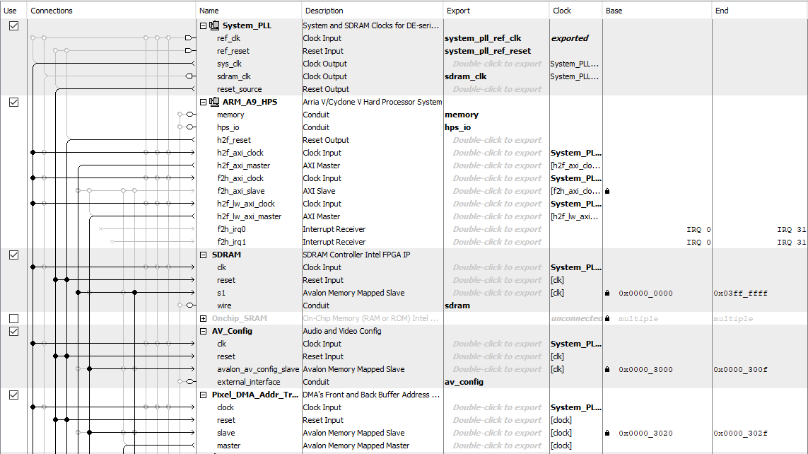
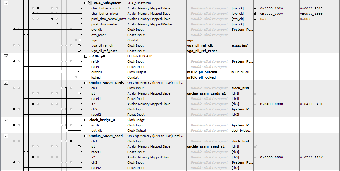
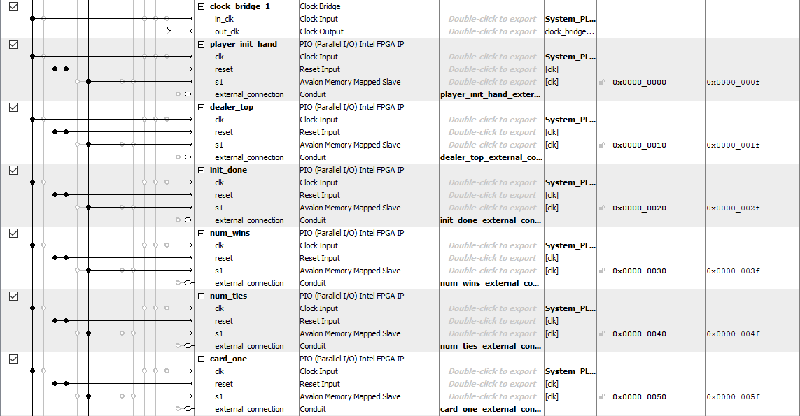
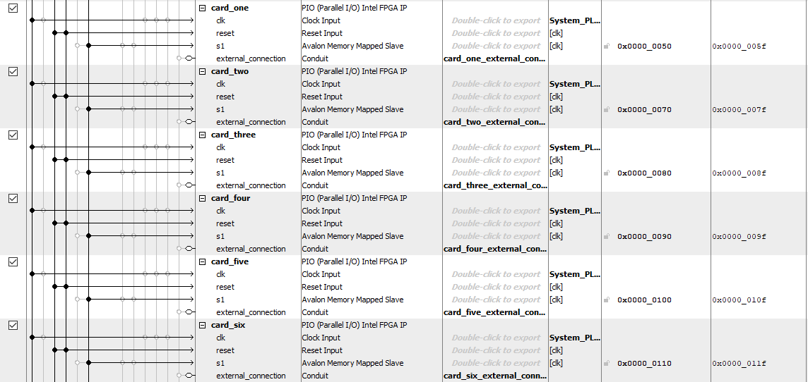
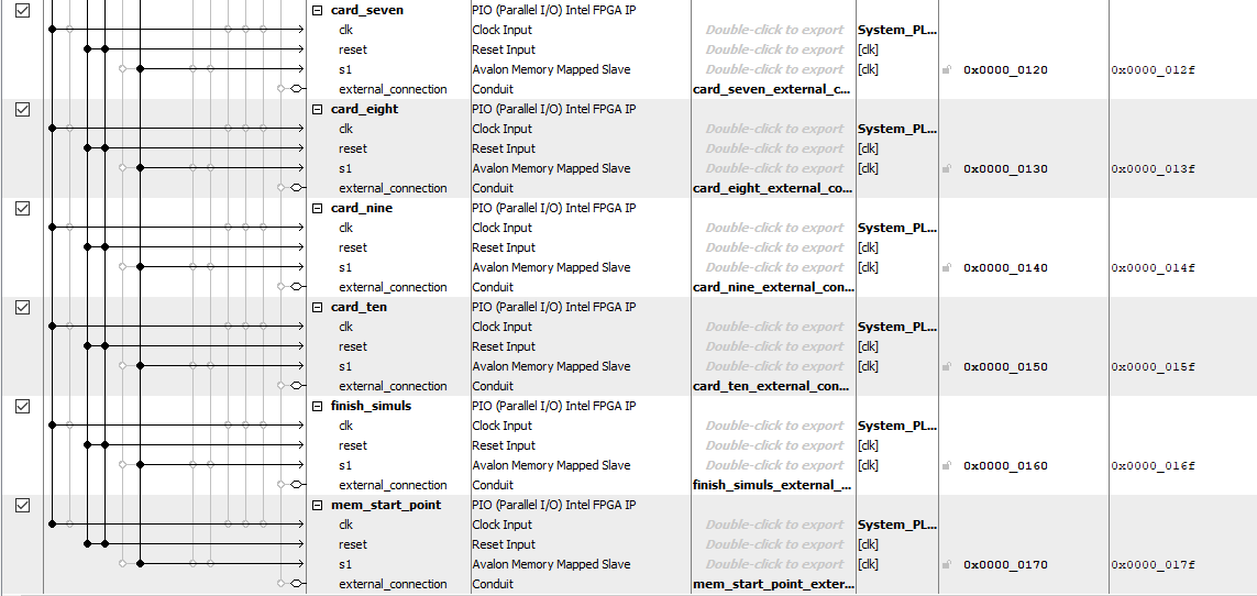
In Platform Designer, we create several OnChip SRAM and Parallel Input/Output (PIO) blocks that create an interface that the ARM processor can access. It's also important to note that PIO blocks are memory-mapped, so they are assigned specific addresses in the lightweight axis master, each with an offset for the lightweight axis master's base address. The OnChip SRAM blocks are assigned specific addresses in the heavy axis master, each with an offset for the heavy axis master's base address. The layout of this can be seen in the figure below:
| PIO block / pointer | Function |
|---|---|
| player_init_hand / player_init_hand_ptr | Store initial hand value of the player(s) when the game starts |
| dealer_top / dealer_top_ptr | Stores value of dealer's shown card |
| init_done / init_done_ptr | Acts as a flag to indicate that the two on-chip memories have been completely filled |
| num_wins / num_wins_ptr | Holds the number of wins recorded by the FPGA during simulations |
| num_ties / num_ties_ptr | Holds the number of ties recorded by the FPGA during simulations |
| card_one, card_two, … card_ten / card_n_ptr | Holds the count/value associated with the “nth” card value in the simulations (to help with “card counting”) |
| finish_simuls / simul_complete_ptr | Acts as a flag to indicate all the simulations are complete |
| mem_start_point / mem_starting_ptr | Indicates the starting address in the on-chip memory where the five decks of cards are stored, and this address changes as cards are drawn from the decks |
| OnChip SRAM block | Size | Purpose |
|---|---|---|
| Onchip_SRAM_cards | 1248 bytes | This on-chip SRAM stores the values associated with each card in the total deck used. The first few slots are zeroed to indicate changing deck sizes after cards are dealt to all players initially and after each player is done with their turn. |
| Onchip_SRAM_seed | 10000 bytes | This on-chip SRAM stores all the random seeds necessary for the random number generators in each parallel block on the FPGA. Each parallel block needs 4 different random seeds and as such under 60 simulations, a total of 240 random seeds are necessary. Each seed is a 32-bit (4-byte) value. This on-chip SRAM has significantly more storage than required to provide greater flexibility in seeding for future implementations. |
Blackjack State Machine
The state machine, inspired by the commonly known basic strategy for Blackjack, operates within a generate block that includes 60 parallel simulations and consists of 13 states:
| State Name | Description |
|---|---|
| State 0 | Check if two of the on-chip memories are filled, and then copy the memory block that stores all the card values into 60 M10K memory blocks inside the generate block |
| State 1 | Fetch a card value from a random address in the M10K memory block, and record the card selected to avoid repetition in card picking |
| State 2 | Implement a buffer state to ensure values from the M10K memory block can be read, addressing the issue of an inferred latch |
| State 3 | Receive the card value, which corresponds to the hidden card in the dealer's initial hand |
| State 4 | Check if the dealer has hit Blackjack; if so, jump directly to State 10 to demonstrate the result |
| State 5 | Fetch a card value for the player from a random address in the M10K memory block that has not been visited before, and record the selected card to prevent repetition in card picking |
| State 6 | Implement a buffer state to ensure values from the M10K memory block can be read, addressing the issue of an inferred latch |
| State 7 | This state gets the next potential card value that could be dealt to the player. Consequently, the card counting register begins recording the card value to inform the next hitting decision. In addition, according to the basic Blackjack strategy, based on the player's hand and the dealer's top card, which is sent from the HPS via PIO, return to State 5 to draw cards for the player if necessary, until the conditions are met |
| State 8 | Fetch a card value for the dealer from a random address in the M10K memory block that has not been visited before, and record the selected card to prevent repetition in card picking |
| State 9 | Implement a buffer state to ensure values from the M10K memory block can be read, addressing the issue of an inferred latch |
| State 10 | Continue fetching card values by returning to State 8 to fetch a value from random addresses in the M10K memory block that have not been visited before. Record each selected card to prevent repetition in card picking. Continue calculating the dealer's hand until the dealer's score reaches 17 or higher |
| State 11 | Check the result and record whether the player wins or ties with the dealer. Then, activate the game completion signal for later result counting |
| State 12 | Implement a buffer state that makes sure another always block to accumulate the results before clearing the registers for starting the next round of game simulation |
| State 13 | To conserve hardware resources, clear the registers used in the simulations within the generate block, and then return to State 1. This process repeats 100 times |
Win & Tie Probability Computation
On the Verilog side, since each parallel generates block runs 100 simulations internally, each generates tracks its wins internally. Upon each parallel block completing its internal simulations, the wins are incremented based on each player's result. Once all internal simulations are accounted for each parallel block, a flag is set across all parallel blocks, indicating readiness for the final result count. A similar procedure is followed for ties as well.
The final result counts are accounted for in a separate clocked module. Within this module, the logic runs through all accumulated results sequentially, incrementing the total number of wins and ties through all parallel blocks. These counts are then communicated to the HPS over the PIO ports highlighted in the Platform Designer Connections section.
On the HPS, the probabilities are calculated in floating point by dividing the net win/tie counts by the total number of simulations. These probabilities are then scaled to be percentages with each percentage recalculated every full simulation.
Card Probability
Inside state 7 of the state machine, the next potential player card value is received from the M10K memory block and recorded. Based on this card value, a case statement within each simulation increments the corresponding register. When the simulation finishes, indicated by the simulation complete signal in state 11, the number is recorded. Eventually, all possible 10 card values from all simulations (6000 in our case) are sent to the HPS via PIO for probability calculation
Given that only the top 5 likely cards are displayed to the user, these card probabilities are sorted after each simulation in ascending order through the QSort algorithm for efficiency. After sorting the card probability results, the top 5 highest counts are stored and displayed to be the 5 cards with the highest likelihood of appearing given a hit command is executed.
Data Flow - HPS + Verilog Integration
Given the presence of multiple internal simulations with each of Verilog's parallel blocks, it became pertinent to incorporate a synchronization methodology. The alternative involves the HPS enforcing a delay to account for the execution time of the FPGA, though the time for the delay would at best be a guess. The synchronization, on the other hand, enables immediate execution of HPS logic and maximizes speed by reducing wait times.
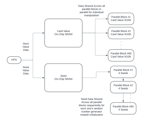
An important aspect of the project is data transfer, both seed and card values. These are both shared between ARM and Verilog through On-Chip SRAMs.
Since each parallel block holds its own M10k block to access and use during simulations, the main Card Value On-Chip SRAM values are distributed in parallel within external clocked logic. All parallel blocks do not begin until the distribution of these card values are accounted for and their individual M10k blocks are filled.
Simulation Count Maximization
The FPGA runs approximately 6000 simulations. However, to attain more simulations and leverage the Monte Carlo effect of probability convergence after multiple simulations, additional simulations are invoked within the HPS. If 6000 simulations that run on the FPGA are considered one block, the ARM executes 2000 blocks per hand or hit to attain the final probabilities displayed to the user. In other words, the total number of simulations run is 12,000,000 simulations with a total compute time of approximately 3.25 seconds. This timing delay is acceptable in this situation given the interactive nature of the game as there exist no time-constrained tasks on decision within the game.
Gameplay
Graphics
The graphics of this game are geared towards using a VGA display connected to the FPGA. The FPGA's memory-mapped I/O is used to control the VGA display (vga_char_ptr allows the program to write text to the screen and vga_pixel_ptr allows the program to draw shapes and colors directly). We make use of several drawing functions to create different elements on the VGA screen:
| Drawing Functions | Purpose |
|---|---|
| VGA_text() | Display string of text |
| VGA_text_clear() / Game_text_clear() | Clear text from entire screen / Clear a specific section of text |
| VGA_box() / VGA_disc() | Draw a filled in rectangle / Draw a filled in circle |
| draw_card() | Draws a playing card at set coordinates with the given value and suit |
| display_card() | Displays cards for a specific player at their designated position and also tracks card indices |
| display_dealer_card() | Displays cards for the dealer at their designated position |
| display_result() | Displays the result of the game for a specific player, including whether they won, lost, busted, or tied, and their bet amount |
Game Flow
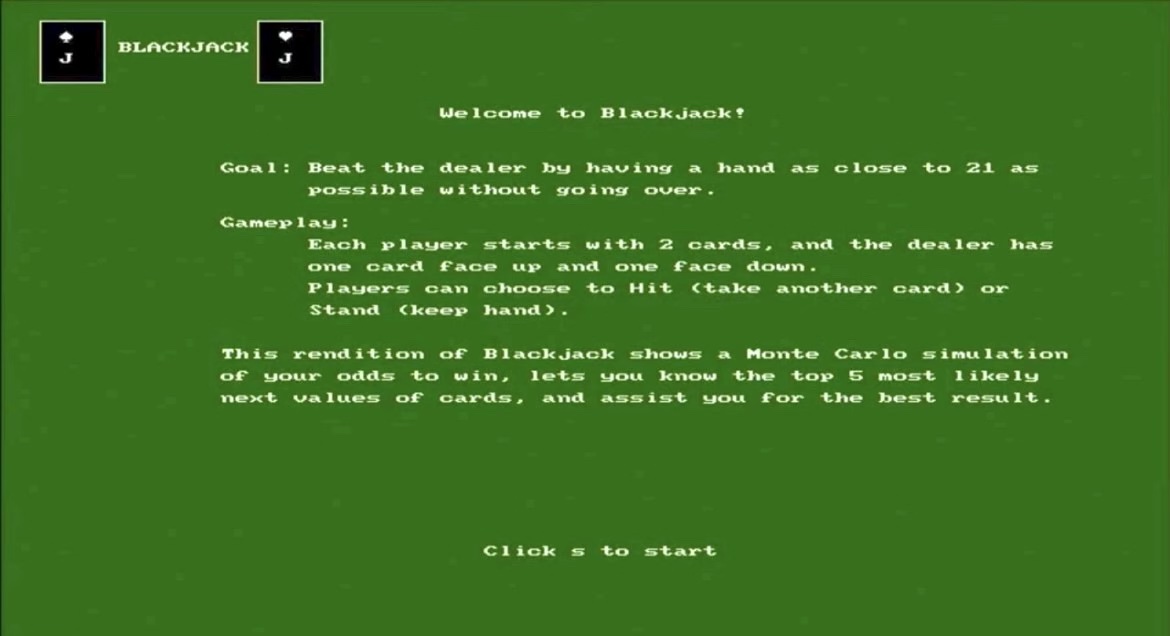
- Main Menu: The game starts with a main menu displayed on the VGA screen, which shows the title, a brief description of the rules, and prompts to move onto the game screen
- Gameplay Initialization: The game initializes by setting up the default screen and prompts the user to enter the number of players
- Betting Phase: Players are prompted to enter their bet amounts
- Card Dealing and Game Play: The game deals initial cards to the players and the dealer; Players can choose to hit or stand, with their choices displayed and updated on the VGA screen
- Result Display: The results of the game are displayed for each player (won, lost, busted, or tied) and their updated chip balance, as well as the dealer's results
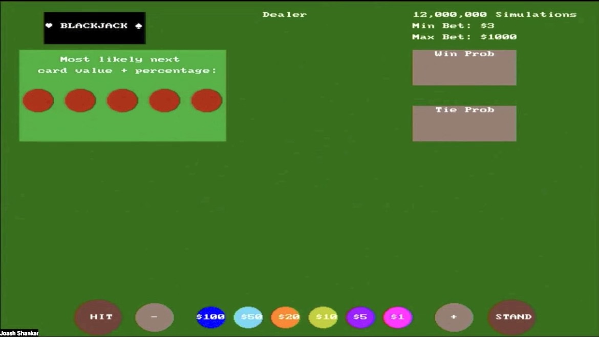
The image above displays the main game interface. At the bottom are UI elements representing chips, incrementing/decrementing options, and hitting/standing options. The empty section is where each player's cards will be laid out. The left side shows the most likely next card value with their respective percentages (based on the simulations run). The right side indicates that the game is running on 12,000,000 simulations, with a minimum bet of $3 and a maximum bet of $1000. It also displays the win probability and tie probability (based on the simulations run). The top middle section shows where the dealer’s cards will be laid out.
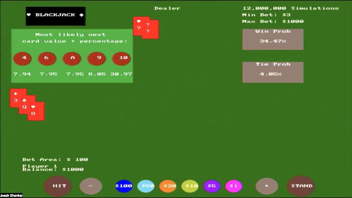
This here shows an example of 1 player playing against the dealer. They bet $100 with their starting balance of $1000. They started with a 3 and a Q (total of 13) where the most likely next card values are shown, with a win probability of 34.47% and a tie probability of 4.05%. The player decides to hit and gets an 8 as the next card value (which happens to be outside the next most likely card value drawn).
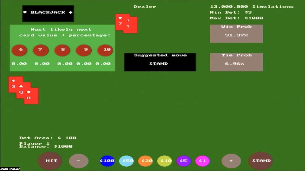
Since this adds up to 21, the most likely next card values all go to 0 since it's recommended to stand now that you are guaranteed to win (since the dealer doesn't have Blackjack). The win probability reflects this as it shoots up to 91.37%, with a 6.96% tie probability.
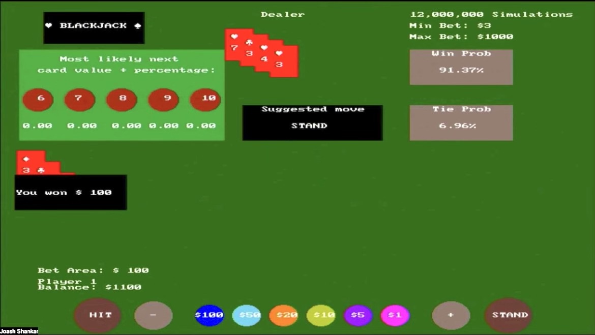
Now that the player has stood and there are no other players, the hidden card of the dealer is now displayed (3 of clubs) as well as their remaining cards drawn. This adds up to 17, and since the player got 21, they won $100 as shown in the black box displayed over their cards.
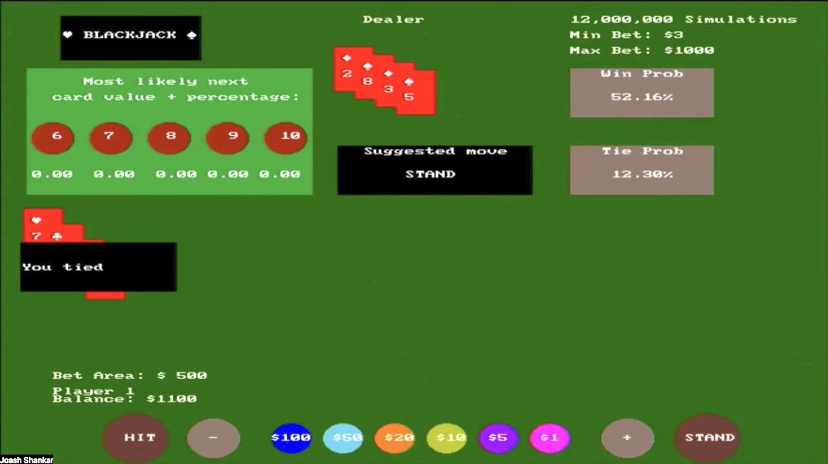
This shows the gameplay of the same user playing another round (indicated as balance starts off with adjusted winnings from the first round of +$100). This also demonstrates a tie scenario, where the player's cards, which add up to 18 as seen on the left before the player stands, equal the value of the dealer's cards as seen on the right.
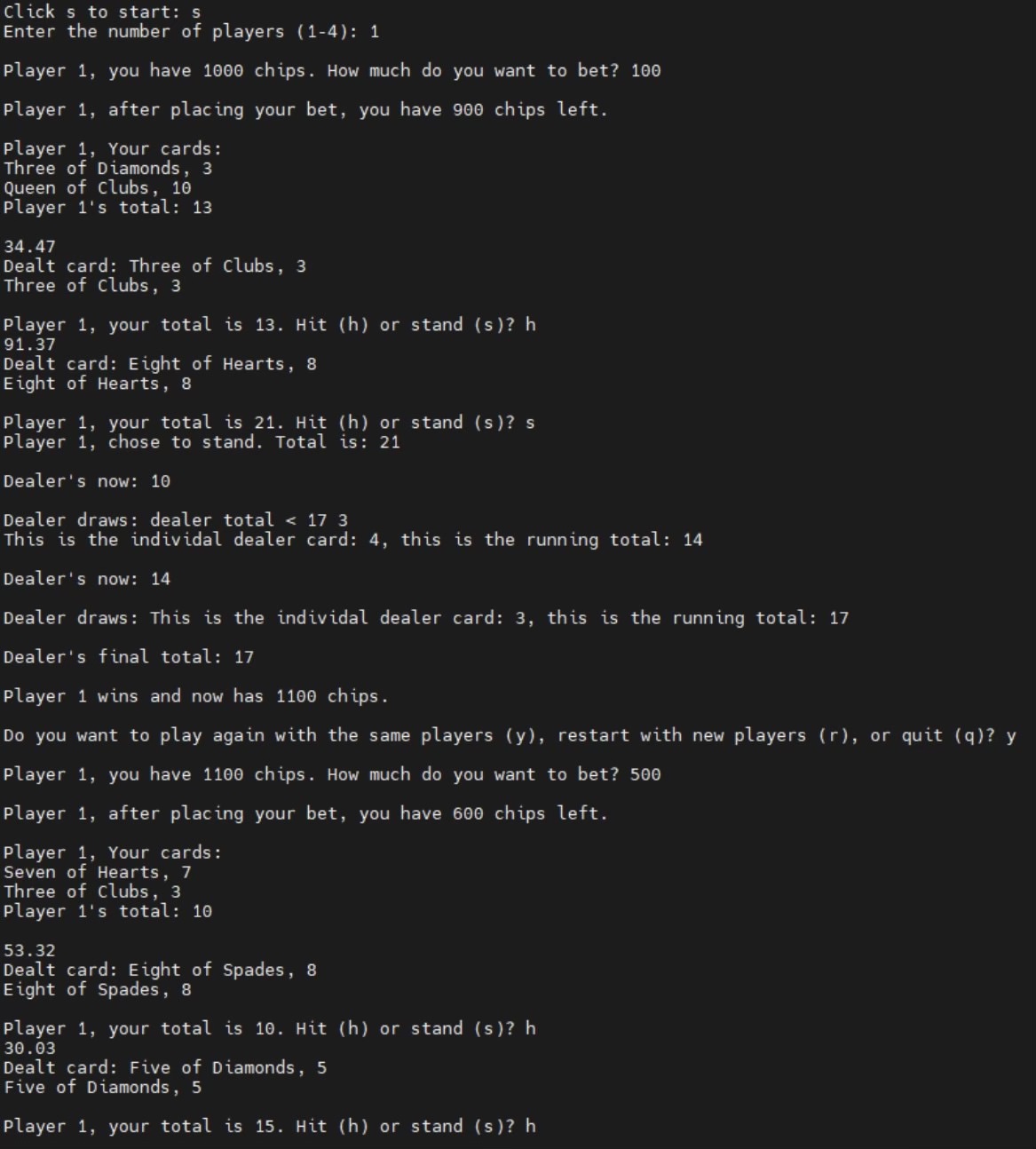
This is an example of the interface the user types into during the gameplay. It starts from the main menu screen, where they are prompted to advance to the game screen by clicking “s”. Then they are prompted to enter the number of players (1-4). The top half part of this screen relates to 1 player simulation. Once the results are displayed, the user is prompted whether they want to play again with the same players, restart with new players, or quit. The bottom half of the screen corresponds to the next section where a player plays another round.
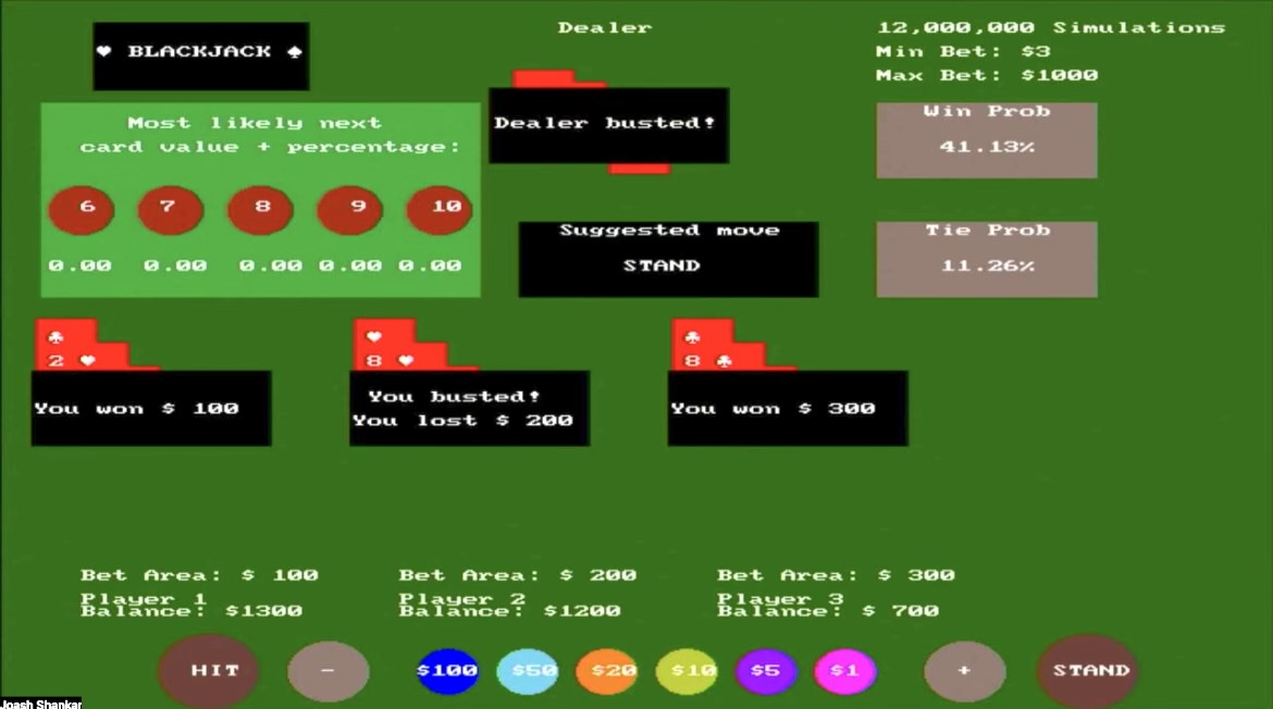
This shows gameplay of 3 players, where the dealer busted so players 1 (total of 19) and 3 (total of 17) won, but player 2 (total of 22) had busted.
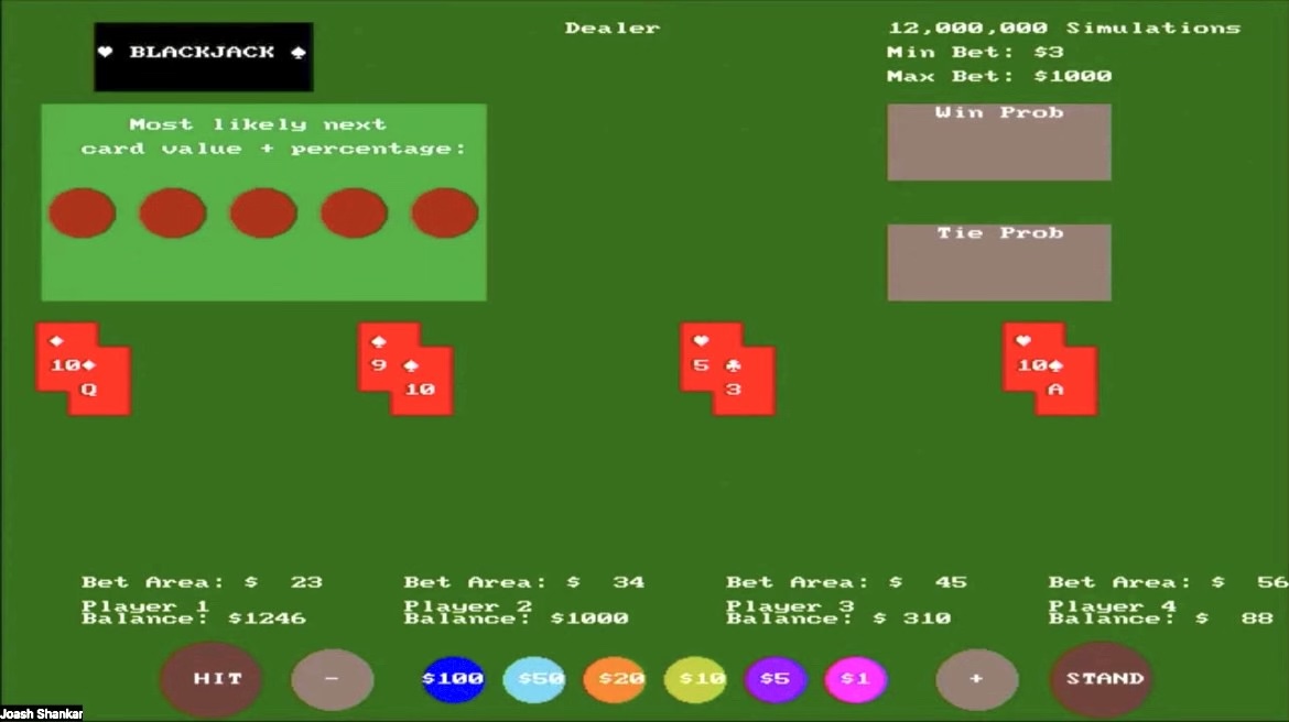
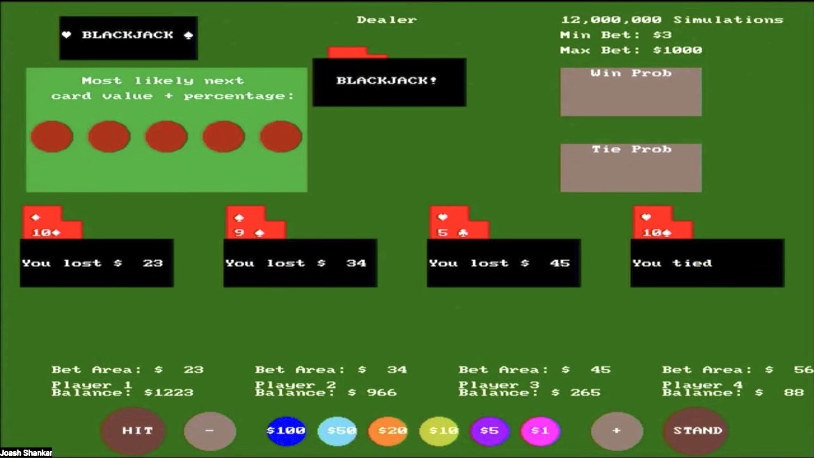
This shows the gameplay of 4 players, where player 4 looks like they are going to win since they hit Blackjack (10 of hearts and Ace of diamonds, where Ace is the value of 11). However, since the dealer hit Blackjack everyone will automatically lose (no players can draw further cards), except player 4 who ties with the dealer.
Results
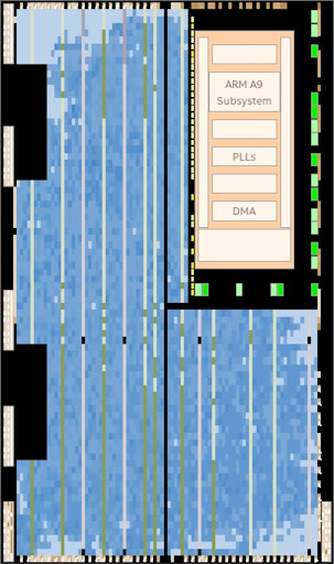
As the chip planner image indicates, the major limiting factor on the FPGA was the ALMs available. The project heavily relied on registers to keep track of temporary results across all internal simulations and higher bit width registers within generated statements to account for the multiple internal simulations run within a parallel block. The final ALM usage amounted to 97% usage with an additional parallel block pushing it to near 103% usage. Memory, on the other hand, was abundant as the project only utilized 34% of available memory despite supporting a major central OnChip-SRAM and multiple duplicate M10K blocks for each parallel block to easily manipulate card values.
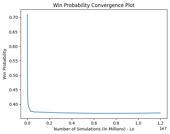
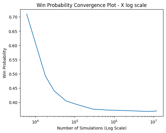
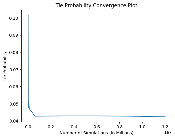
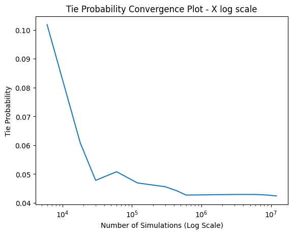
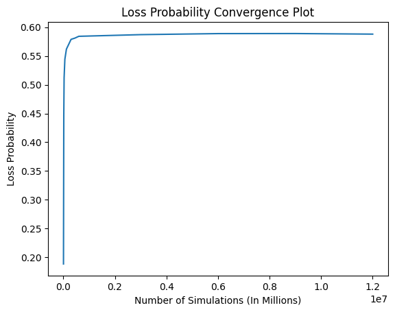
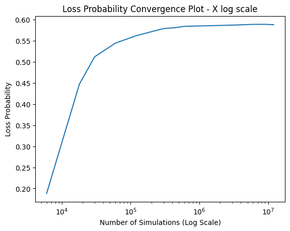
The plots above display the convergence plots through multiple runs. The goal remained to find out what simulation count the probabilities would start to converge towards a steady value considering the same hand for the player and dealer simulation-to-simulation. The observed result was that between the 450,000 and 600,000 simulations, the probability for all measurements - loss, wins, and ties - started to plateau and converge to a singular value. As the plots indicate, after the point mentioned above, the probabilities are largely stationary, forming a near-straight line with only minor differences in the decimal point of the percentages.
Conclusions & Future Work
Our design meets the expectations set in the proposal. Our project does not infringe upon any IP and does not reuse publicly available code.
It was a great learning opportunity to explore more about On-Chip SRAMs, random number generation, Monte Carlo methods, and FPGA+HPS integration.
A future improvement our group would like to implement would be to optimize the state machine. Currently, our state machine utilizes 13 states, though nearly 4 to 5 states function as read buffer states from the local M10k memory. An improvement would be to experiment with single cycle reads, especially since only 2 On-Chip SRAMs are being shared between the ARM and FPGA.
A second improvement our group would like to incorporate is reducing the dependence on registers. As mentioned prior in the report, the biggest obstacle in this project was the ALM space constraints. However, moving more data to memory locations that can be more easily manipulated per internal simulation will include a greater number of parallel blocks on the Verilog side. Since only 34% of the memory is utilized, this potential improvement certainly makes the incorporation of this suggested improvement possible.
Appendix A
The group approves this report for inclusion on the course website. The group approves the video for inclusion on the course youtube channel.