Recapitulating, the NTSC video signal consists of two components, the luma signal which tells the TV the brightness of a "pixel" and chroma signal which tells the color of the "pixel". The luma signal is simple enough. Higher voltage levels represent brighter spots while lower levels represent darker spots. The chroma is a tad more complicated. Color information is QAM modulated onto a subcarrier wave.
Some of techniques used to generate NTSC color are
1. Doing the QAM modulation in analog hardware. With all the recommended filters, this easily produces the best results. Whats more, the input can be in the form of RGB which is a big advantage over doing something in some unknown color space. The AD725 does this. The drawback is that its rather expensive and takes out most of the fun from NTSC color generation. Hobby projects are most often fun because of the DIY nature of the project. Having an ASIC do the job is a downer for me.
2. Putting out square waves instead of sine waves and controlling the phase of the wave. Achieves really good results. Most suitable on an FPGA where a phase accumulator can be easily designed. Implementing PAL is also quite easily possible. See [2]
3. A variant of #2 that uses discrete hardware. A series of NOT gates or buffers can be used to create phase delays. Various points on the delay chain are tapped and fed to a multiplexer. The microcontroller selects which phase to be output at that point of time so that the "pixel" has the color its supposed to. Needs a LOT of hardware and wires. You are left at the mercy are delay variations over temperature , manufacturer and batch of the chip. See [3] , [4] and [5].
4. A variant of #2 that uses SPI to create phase delays. This easily requires the least hardware. At high enough SPI Clock, a wide range of colors can be obtained. At 28.636Mhz ( 8 x Fsc ), 8 phases can be created. This allows for 8 "pure" hues and a number of mixtures, many of which are identical. This technique is great but there is a slight catch. If implemented as per NTSC spec, each line is 227.5 cycles long. So the phase of the color burst inverts if you take the sync tip as reference for each line. Implementing this inversion happens automatically with other techniques. But with SPI, this has to be done manually. When using this technique, this inversion is ignored and the length of each line is rounded to either 227 or 228 cycles. But this results in poor color transitions with distinctly visible bands at transitions. See [6] , [7].
Here's one technique I came up with that no one has used so far.
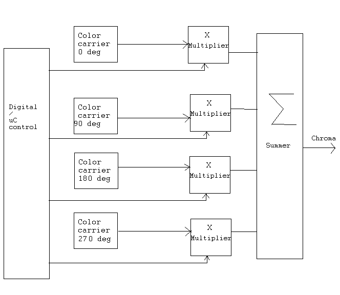
5. A digital variant of #1. The idea is create different phases of the color carrier ( either by a delay chain or ring counter ) and instead of multiplexing the outputs, we add the phases in a manner that can be controlled digitally. I've been able to get this to work on LPC1768 and Atmega16. I'll publish the results soon. It requires minimal extra hardware and enables even the slowest 8-bitters to generate NTSC color video.
References
1. AD725 Datasheet
2. PAL using FPGA
3. XGS AVR
4. Lazarus-64
5. Atmega64 GameStation
6. RBox
7. Apple II graphics
That's an odd way of showing example 5, look at how the NES did it's color phases. It used a ring counter as you said, and the input into the 0th register is the inverted output of the last register. This gives both the negative and positive versions of the outputs which are then input into a n:1 mux to select the output, where n is the amount of color divisions. (Actually it's a little more complicated in the actual hardware, via the patent, but it's cool!)
ReplyDeleteSo if you were to take the clkout of the LPC1768 to clock them, you'd have full color in about 3-4 74xxx IC's
ReplyDelete+--------------o<|-------------+
+-[R]->[R]->[R]->[R]->[R]->[R]-+ 0V 5V
| | | | | | | |
---------------------------------------
[ 0 1 2 3 4 5 6 7] <- hue[2:0]
---------------------------------------
| o
| |
---------
[0 1]<-- hue[3]
---------
|
digital color phase signal
piss poor drawing, sorry!
Oops, it didn't draw correctly. Basically you have an inverter up top taking the last registers output as the inverter's input, and outputting it into the first register's input.
ReplyDeleteYou take the outputs of each register and put them into a mux, selecting which one of these represents your hue. You can either input both the outputs and their compliments, or you can just two smaller multiplexers to output the final digital chroma signal
Oh, and of course, the each register, rn's output goes into the input of the rn+1. Lastly, you clock these registers at n times the frequency of NTSC (or PAL). So if you want 12 different hues, you have 6 registers and clock the registers at 6xNTSC. If you want 16 different hues, you have 8 registers and clock them at 8xNTSC.. etc etc..
ReplyDeleteNo more posts until a reply, I promise! SORRY! If you want to condense this all to one post, please do!
Thank you for the insight on the NES system.
ReplyDeleteThe idea in method 5 is to do all of the things in the figure with only passive components. I havent had time to put up the circuit.