Shape Memory Alloy Prosthetics
|
Benjamin Madoff |
Usuf Husain |
Bruce Land (Faculty Advisor) |
Abstract
The shape memory alloy prosthetics project is the starting
point for a prosthetic hand. The goal of the project is to create a prosthetic
capable of fine finger movement. The focus of the design was the creation and
analysis of finger joints using shape memory alloys as flexors and spring steel
as extensors. While single joints are easy to control, any system with multiple
joints creates coupling problems between joints. This problem could be solved
with active control of each joint, but would be better solved using methods that
minimize the number of control signals. While this project focused on the
robotics, future work with myoelectric control of the hand would be needed to
complement this research.
Introduction
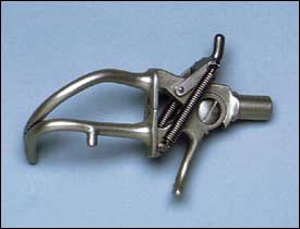
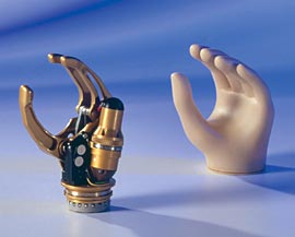
The goal of this project is to use shape memory alloys to create a prosthetic hand. Prosthetic hands today come in two varieties, body powered and myoelectric. Most body powered hands are hooks or other simple tools, as shown on the left. Myoelectric hands are those that take electrical signals from muscle contractions in the body to control a motorized hand, as shown on the right. These hands generally have three fingers (but include a glove with additional passive fingers) and a wrist that rotates 360°.
|
|
|
Figure 1: Current prosthetic hand technology, human powered hook on the left and myoelectric hand on the right
The goal of this project is to create a new myoelectric hand. The control signals are not within the scope of this paper. Control signals may be derived from signals on the surface of the skin or from sub-dermal signals, depending on what is available when the robotics portion of the project is complete.
The goal of this project is not to replicate other myoelectric hands, but to create a new type of myoelectric prosthetic hand capable of fine finger control, such that the user could type or play the piano the same way a person with an organic hand would be able to.
High Level Design
Shape memory alloys will be used as actuators, simulating the action of the flexor muscles in the fingers, hand, and wrist. The ultimate goal of this project is to develop a full prosthetic hand; this semester the research focused on creating a full prototype hand. Shown below is a rough schematic of the design for the first four fingers. The thick black lines represent the shape memory alloy, used to control each joint. The thin black lines represent power going to the actuators. The boxes beneath the hand, power, microcontroller, and switching circuitry, represent the supporting circuitry needed to control each actuator.
Figure 2: Model of the basic components for actuation of the first four fingers
Shape memory alloys are unique metal alloys that they contract when heated. The material does not actually contract, but, in the case of a shape memory alloy wire, expands radially much fast than longitudinally, so the overall effect is longitudinal contraction, as illustrated below (exaggerated).
|
|
à |
|
Figure 3: Example of how shape memory alloys “contract”
When the alloy is cooled, the material can regain its original shape. The ability to contract and relax enables shape memory alloys to simulate muscles.
The most common shape memory alloy is nitinol, an alloy of approximately 50% Nickel, 50% Titanium. Nitinol has two properties that make it exceptionally useful: the super elastic effect and the shape memory effect. The super elastic effect gives nitinol processed under certain conditions to regain its shape after it is deformed. This is the more common use for nitinol, but not the one used in this research project.
The shape memory effect refers to the ability of the material to remember its shape even after repeated heating and cooling cycles. This effect applies to the material only when the deformation is 5% or less of the total length of the wire. If the deformation is 5% or less, the nitinol wire can contract and expand approximately 10,000 times. Nitinol can deform to 10%, but damage to the crystal structure limits the repeatability to about 10 times. If the deformation is greater than 10%, it is likely that the wire will contract only once.
There are two stable phases of nitinol wire, the martensite (a-phase) and austenite (b-phase). The austenite phase is only stable above a given temperature and the martensite phase is only stable below a certain temperature. In the austenite phase, the atoms in the nitinol wire form a uniform crystal structure. When deformed into the martensite phase, different portions of the nitinol form different crystal structures. The different structures expand the nitinol wire to a shape greater than the austenite phase. At room temperature, the material is in the martensite phase. When heat is applied, the material transforms into its austenite phase. The net effect of the new shape is a contraction.
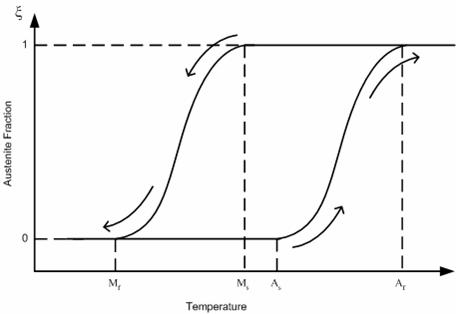
Figure 4: This graph shows the transformation of the nitinol between the martensite and the austenite phases. The transformation is reversible over temperature ranges determined during the formation of the material.
This graph shows the transformation of the nitinol between the martensite and the austenite phases. The transformation is reversible over temperature ranges determined during the formation of the material.
In nitinol wire, the force is proportional to the length squared (F α L2), and the work is proportional to the length cubed (W α L3). The force is also proportional to the temperature of the wire. The temperature depends on the amount of current running through the wire, but the amount of current depends on the resistance of the wire, which in turn depends on the temperature. For this reason, controlling the force applied by the actuator requires a feedback system.
The base of the prosthetic hand is composed of a plastic material, Delrin. Delrin was chosen because it is easily to machine, resistant to high temperatures, and non-conductive. A non-conductive base that is resistant to high temperatures is crucial to the prosthetic hand because the nitinol wire heats up to almost 70 degree Celsius during use. The fact that Delrin is easily machinable enables us to easily test and make quick adjustments to various designs.
Hardware Design
The prototype evolved in four major stages, as shown below.
|
|
|
Figure 5: Aluminum based prototypes
The original prototypes used syringe tips as mechanical anchors and electrical contacts. As the prototype evolved, the base length increased to increase the power applied by the nitinol wire. A bridge was added to the base to arch the nitinol. Keeping the wire flat against the prototype makes it more like a muscle. Nylon screws were used on the aluminum plates to separate the nitinol wires from the base, preventing short circuits.
|
|
|
Figure 6: Delrin based prototypes
The aluminum base plates were replaced with Delrin, a plastic, to prevent shorts, making the mechanical construction simlpler. Wire terminals were used instead of syringe tips, and notches were machined in to keep the spring steel fixed. Cable ties were added to keep the wire taut, and the spring steel was angled downward to increase the bias on the nitinol.
The main joint is shown below:
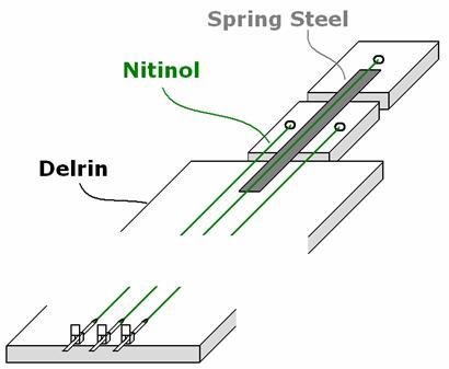
Figure 7: Three dimensional representation of the model.
The end of the nitinol that is connected to the finger joint is held in place by a screw. Cable ties at end of the base are used to keep the nitinol taut. If the nitinol is not taut while current is applied, the wires will suffer some permanent deformation. The spring steel is held in place by drilling a hole through it and screwing it into the Delrin base.
The nitinol strands stretch across the base and to the finger joints. Although not shown in the diagram, one end of each wire is connected to ground while the other is connected to power. When current is sent through the nitinol strand, the wire heats and contracts, pulling the joint towards the base. When the current is stopped, the nitinol cools down and returns to its expanded shape. The spring steel is used to pull the joint back quickly. The tradeoff is that the nitinol strand must have enough power to overcome the spring steel, but it allows for quicker movement of the joint since allowing the nitinol to cool and return on its own would take a while.
To determine the length of spring steel to be used, force tests were performed to find the length that would provide enough force to pull the nitinol back quickly yet not require too much power to bend the joint. The tests were performed with three lengths: 0.85”, 0.75”, and 0.6”. The tests were able to be carried out for the 0.6” length due to the small size and limited testing capabilities. The results are shown below for the force required to bend the spring steel at different angles:
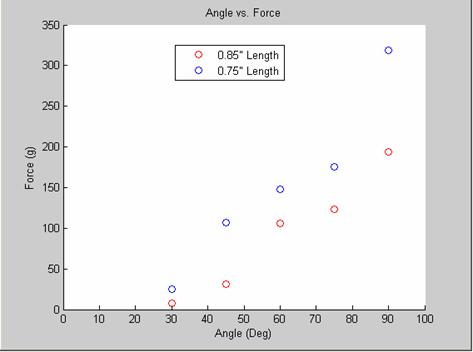
Figure 8: This graph shows how much force it takes to bend spring steel of given lengths to specific angles.
The longer the length of spring steel, the less force required to bend. It was found that the 0.6” spring steel worked the best through testing in the prototypes, despite the lack of test results. The short spring steel would allow for recovery after a flex of the nitinol at the cost of more power to flex. In prototype testing, the longer lengths of spring steel did not satisfactorily pull the joint back, so the shorter length had to be used.
In our tests so far, the nitinol wire required about 0.5A to begin the contraction. Increasing the voltage, and thus the current, made the phase change of the nitinol from the martensite to the austenite phase happen even quicker.
One of the problems experienced during testing was lateral movement of the joint during contraction. This was due to the difference in the lengths of the nitinol wire to the first joint. One wire would contract more than the other, pulling the whole joint towards it. This was resolved by cutting into the Delrin base and putting the spring steel in a gap in the base. The spring steel would stay fixed and not be able to move to the side, only bend upwards with the nitinol.
The second problem was with the second joint. The second joint was unable to flex independently of the first one. When current was applied to the nitinol wire controlling the second joint, the first joint would also list.
The thumb joint is shown below:
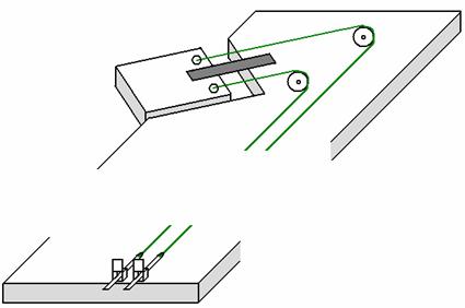
Figure 9: This figure shows a three dimensional model of the thumb.
The thumb is fixed to flex over the base at a 45 degree angle to meet the other fingers. To position the nitinol properly at a 45 degree angle, pivots points were used at the end of the base, near the fingers. The pivot points redirect the nitinol wire so they are perpendicular to the thumb joint. The two strands of nitinol must be the same length to maintain the same contraction when heated and not allow for lateral movement. The same method of placing the spring steel into a grove in the Delrin was used to further prevent the lateral movement.
Software Design
An Atmel Mega32 Microcontroller is used to send control signals to the prosthetic hand. The control signal is sent to the base of a MOSFET that controls the currents flowing through the nitinol.
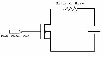
Figure 10: This schematic shows the circuit used to stimulate the nitinol wire
A PWM signal is sent to gate of an NMOS transistor. The Mega32 microcontroller has an onboard PWM generator, but not enough. There are three timers on the microcontroller; each has its own PWM generator. Initially, when testing a single joint, we only needed one control signal. However, ultimately we need one signal for each joint, two joints on each finger, and five fingers. A total of 10 control signals are required.
The PWM serves a dual purpose: it prevents hot spots from forming and adjusts the current through the wire. The PWM is the only control available to determine the output, the mechanical force at each joint. The only caveat is that the resistance of the nitinol wire varies with temperature, meaning some feedback control is necessary to balance resistance and temperature. The most likely source of control, though, would be the eyes of the user of the myoelectric arm.
To manually create the PWM signals, we used the same method the microcontroller uses for its PWM. A counter, TCNTx, runs on a timer, counting to 0xff and then resetting to start over. Before TCNTx reaches 0xff, when TCNTx is equal to the value stored in a register, OCRx, a port pin connected to OCx is toggled. This process is shown below:
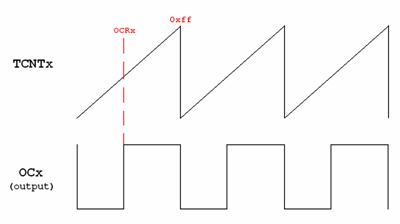
Figure 11: This figure shows one method of generating a custom PWM
To generate our PWM, we used this same process with our own variables. A single timer is used for a counter, Counter. Counter is reset when it reaches the value stored in period. The point at which the output is toggled is calculated by multiplying the desired duty cycle by period. If a 50% duty cycle is required from a period of 100, then the output is toggled at Counter == 50. An array contains the duty cycles for each PWM signal so each duty cycle is independent of the other. The actual period of the PWM is common for all signals, but can easily be independent by creating a second array for periods.
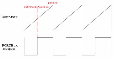
Figure 12: The duty cycle of the PWM can be changed and output on PORTB, although the period will remain the same.
A potentiometer allows us to easily adjust the duty cycle without having to manually enter code. The ADC on the Mega32 reads the voltage across the potentiometer, adjusting the duty cycle based on the ratio of the voltage to Vcc.
Matlab was used to log data during testing. The microcontroller connects to Matlab using the RS232 interface. A Matlab script reads data sent by the microcontroller and stores it into an array. The data can then be graphed and analyzed.
Results
Most of the results have been stated in the design sections. Most of the design changes made over the course of the project have been minor changes to accommodate unexpected problems, like the lateral joint movement. The biggest change that needs to be made is to the second joint. A new design is discussed in the conclusion section.
One of the major goals of the project has been completed; the nitinol joint does indeed work. The current contracts the wire and the spring steel pulls it back during cooling. The non-conductive Delrin base allows for easy modifications during testing and does not interfere with the nitinol, electrically. The thumb joint is also a success, albeit with limited motion.
The coding portion of the project has not been as difficult as the mechanical portion. At this point, the only control needed was turning the current on and off. The control will play a much larger role when precise movements are required.
Conclusion
The next steps in this research project are straightforward extensions of the work presented in this report. The second joint for the fingers needs to be reworked and tested. The current idea is to separate the two joints by the amount of power required to flex them. By putting more spring steel on the first joint, the nitinol wire will need more current to overcome the force holding the finger down. When the second joint is flexed, the nitinol wire running to it will have enough power to overcome the spring steel, but not the two pieces on the first joint. Testing also needs to be done with respect to the force of the nitinol on each joint.
The layout of the hand needs to be considered. Each finger requires two strands of nitinol in addition to one for the thumb for a total of 11 strands. Each strand cannot make contact with the other yet has to be long enough to provide the necessary force. The curved strand for the thumb will prove especially difficult to place. It must cross the width of the hand and be properly positioned to allow the desired 45 degree motion.
On the software side, a current sensor needs to be added. The current sensor is the feedback that is needed to sense the amount of contraction of the nitinol. As the wire heats up, the resistance changes. By tracking the change in current, the resistance can be measured. A voltage sensor will also be used to track the voltage drop across the nitinol. By knowing the amount of contraction, the microcontroller can adjust the duty cycle to speed up or slow down the contraction to reach a certain point. A certain amount of contraction can also be maintained to perform various actions.
Once the hardware portion is complete, the project will shift focus to the myoelectric control signals. Research needs to be done to interpret the body signals and convert them into the proper control signals to the prosthetic arm.
Appendix