Introduction:
Using the Lantronix Xport, I gave networking capabilities to the Atmel Mega 32. These capabilities are used through a friendly API, making it easy to use for students in ECE 476. I also implemented some examples that are useful in real life. The first example is sending light data over the network, and adjusting the level at which an LED will turn off and on. In addition I also have a temperature sensor which will turn on or off an LED once it hits a certain threshold. These examples are a good starting point for anyone who wishes to expand the network capabilities of the Atmel Mega 32. In addition, this could be used with any microcontroller that has serial communication capabilities.
High Level Design:
Rationale:
Increasingly, we see more and more applications of the internet. Everything is starting to have network connectivity, and this will be even more the case when wireless networking becomes more readily available. Everything from kitchen fridges to security systems to light switches can now be controlled or monitored via the internet. Bearing this in mind, I decided I would give networking capabilities to the Atmel chip used in ECE 476. I wanted something, moreover, simple enough to be used by ECE476 students. The use of Lantronix Xport, which converts serial communication to internet communication, made this possible.
Logical Structure:
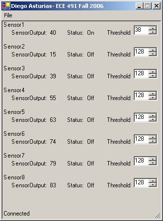
The logical structure is a simple and intuitive one. The sensors connect to the Atmel chip’s A/D converter. All eight of the A/D converters can be used, as all area read every 400ms. The results are then sent out through the RS232 serial connection. The serial connection goes to the Xport, which converts serial communication to TCP/IP packets. Then we can connect to the Xport through a java applet that it hosts on its website. The applet receives the serial information as if the Xport were not there, and then interprets it and places it onto a GUI.

Hardware Design:
PCB Board:
The PCB board design was fairly aggressive in minimizing area so that it would fit on half a board. This was so that a cheaper standalone version of the board could be made. However, a smaller design could be made if no serial chip were needed. This would be the case if the Atmel chip were placed on the same board. The voltage regulator to be placed on the board can only handle a ~6v power source. This means that if the same power source as the Atmel were to be used, then a different voltage regulator should be employed. In addition, the Xport draws ~300mA max. One other thing that might want to be changed about this design is the fact that CP1, CP2, and CP3 are all grounded. These connections could be changed to serve some software programmable purpose.

Serial Communication:
The Lantronix Xport has built-in serial communication. These pins are 5v tolerant, but are 3.3v logic level. When designing the PCB board I decided that I wanted a more modular design, so that this board could be used with not just the Atmel chip, but with anything that has a serial interface. The serial chip that is normally used in ECE 476 could not be used in this case, however, because it could not be used with 3.3v. In addition, it would be the only thing on the board that required 5.0v power source. With this in mind I found the MAX3232 serial chip, which can be used with either a 5v or a 3.3v power source. However, the serial could be used with the Atmel chip if it was placed on the PCB board and level shifters were used.
The female serial header that I used on the project presented a problem, because the STK 500 also has a female connector. I discovered that, for serial communication, Male-Male cables have their transmit and receive wires reversed. However, I wanted to maintain the ability to hook up the Xport to the computer, achieving this by making my own serial cable. It appears to be a normal serial cable except it has the transmit and receive reversed, so that the cable works as expected.
Shield:
The shield tab serves two purposes on the Xport. The first is to serve as ESD protection. Because of this the shield tabs should be hooked up to Vcc and ground via a high voltage (~200V) low ESR capacitor. I have used a 630V low ESR capacitor. It is hooked up to Vcc and Ground so that in the case of a discharge the voltage rises equally on both, without danger of misbalance. The other purpose of the shield tabs is for heat dissipation. Ideally the shield tabs should be hooked up to 1sq in of copper. With 1sq in the Xport is rated up to 85C with a 10C safety margin. In my PCB design I have put in the 1sq in of copper; however, one design element I would change is to put the cooper on the bottom layer instead, improving the Xport’s conductive path to it.
Software Design:
Communication Format:
The communication format is where one might want to significantly modify this project, depending on the application. At present it takes ~3 times the number of bytes as necessary. The number of necessary bytes is 26 bytes; however, it currently uses 74 bytes. The reason for this is that the information being sent from the microcontroller is being sent as a C string. So if the number being sent is 128, it sends 3 bytes, because it is 3 digits. The reason for this separation instead of just sending the char value is for debug reasons. When I was testing the system, I connected the microcontroller to hyperterm to ensure the output was what I expected. However, not all of the char values have visible ASCII values associated with them. For example, if the value being sent over were 8, nothing would show up (a square best case).
For transmitting to the microcontroller, I use the following format. 127, sensor num, new threshold, 126. Every serial communication starts with 127, and ends with 126. This informs us when we have a complete transmission, so we do not rely on an expected length of transmission. The sensor num is 1 byte, and new threshold is 3 bytes for the reason explained above. This information is sent every time something changes on the form.
For transmitting from the microcontroller, I use the following format. 127, sensor data, threshold, on or off, …, 126. In the … area we just send sensor information for the other 7 sensors. Again, these values (except for the 127 and 126) are sent in their C string equivalent, and are padded with spaces if they do not reach the size of 3. This has allowed for quick debugging, but is very inefficient. This can be changed if bandwidth is a consideration in the project.
Java:
For this section I am going to explain the control flow of the Java version. While the C# version has a very similar control flow, some notable differences are noted in the next section. The Java program begins by pulling arguments that were passed to it. The first argument is the IP address to connect to, and the second is port to connect to. If the program is not being run as an applet, the IP address is mandatory, while the port is not. The default port used if no port is specified is 10001. However, if a different port is specified, the Xport settings must also be changed. In addition if the program is being run as an applet, then all arguments are ignored and the standard 10001 port is used.
Once we have parsed in the arguments, we attempt to connect to the Xport. To do this, you can either use the default constructor, which forms the connection immediately, or you can connect later. Since this code is intended to be used as an applet and a connection should be formed as soon as the website is loaded, I opted to go with the former. If a connection fails to form, then the applet will tell you that it has failed, but with no specific message. This is one area that might be improved in the future. Instead of having the error print out to the console, have the error print out to the Gui so that the end user gets are far more informative messages. If we get past this point, then the Gui is formed for communication to and from the Xport.
The code to connect, read and write to the Xport is actually fairly trivial. When forming a connection we open a socket and connect to the Xport. We then create a stream reader and writer with the socket’s input and output stream respectively. In addition all of the functions in Xport code are thread safe and tried catched. Any errors that are catched are printed out to the console. To read and write with the Xport it is identical to how one would normally use these streams, as with files. The only notable modification done to this code from the original code that Lantronix provided is the receive function. In the original version if the receive function was called and there was nothing in the buffer, then it would just go into a loop until something was there. The only way to get it out of this loop was, when the connection was closed, it would throw an exception, get out of the loop or till something is placed into the buffer. Therefore this code would always terminate, but not in an ideal way. However, the original code avoided this problem by identifying if there was available data in the receive buffer, and only call this function if that was the case, thus never getting stuck in a loop. This approach is not very defensive and can cause unexpected behavior from a programmer unaware of this limitation. So instead, I changed it so that if there is no available data in the buffer, it will return null. As long as the programmer checks for the null condition, he is set.
The meat of the program is in the Gui.java. In the constructor of this class, we start off by initializing all of the labels and spinners that we put on the form. We save references to all of these labels so that we can update their values in the future. However, saving references to all of the labels is not strictly necessary, because only 16 will need to be changed. In addition, we initialize the spinners to 0, and add the range from 0-255. The last thing that we do is initialize the receive thread which is responsible for pulling out transmissions from the Xport and updating the Gui with their change.
The receive thread first checks to establish if we have a valid connection. If we do, then we read the input buffer to see if we have any new data. If we have new data and it is valid, then we proceed and decode the data, which will be in the format specified in the communication format section. Once we have the data decoded we can then just print it out to the screen.
The packet fragmentation issue is the only element in this area that really needs some work. Let us say that we ask for a packet, and we only have 0.5 waiting in our buffer. We reject that in the current scheme. What needs to happen is to either change the networking code so as not to clear the buffer on clear, but instead have another function that does that. Alternately, the best solution in my opinion is to have another buffer to store what you receive. Every time you receive, you search through the buffer to determine if you have a complete transmission, and remove it from the buffer.
Whenever we change a value in a spinner there is a callback to a function. This function forms a packet of the format specified in the communication section, and then sends the packet of data. One problem in the process causes the spinners to sometimes behave strangely. Let us say that you send an update of setting the threshold to 10. If the current threshold is 11 and the microcontroller is currently sending out that packet, then the program will receive 11. Let us say that value was then changed to 11. After noting the change in value, it will send another packet to the microcontroller saying it is now 11 rather than 10. One can prevent this only by detecting when the value is changing, because of user input or microcontroller changing setting the value. However, I am not sure how to accomplish this.
Difference between Java and
C# version:
There are not too many differences between the java and C# versions of the program. However, one thing I decided to do differently in the C# program was to not use a separate thread to receive new updates. The C# program uses the timer class that has a call back to an update function every 1000ms. This was done to show that the program could be done in a single-threaded fashion, since not everyone has experience using multi-threading. However, the C# program could have been implemented in the same manner as the Java program.
Another notable difference is that the C# version uses the exact same Xport code to send, receive, and connect as the Java code. To do this I compiled the Java code using J#, which is a .Net language. Since all .Net languages work with each other, I can just import the J# assembly into the C# program. However, because it is Java code—and Java, unlike C#, does not have unsigned bytes-- when sending and receiving bytes in c# it will ask for a sbyte rather than, as in Java, a byte.
The program’s connection to the Xport is also setup in a slightly different manner in the C# and the Java versions. In the Java version, as mentioned above, we can get the IP of the Xport in two fashions: either through command line, or through the IP of the server that the applet is being served off of. However, for the C# version I wanted to have a more conventional system familiar to people. So the only way to connect to the Xport is through going via the menu system. The benefit of this is that it allows being able to connect at any time, and not only at start time. In addition, it allows you to disconnect and reconnect to another Xport. However, since the C# version of the program was not the main focus of this, this feature has not been fully tested. Furthermore, in the C# version you cannot specify the port to connect to the Xport, a feature which did not seem important
The last thing to note is that the complete Java version could have been compiled with J# or been converted with Microsoft Java Language Conversion Assistant 3.0. However, this was not done to show how a GUI could be implemented in C# vs Java. The reason one might want to use C# instead of Java is that .Net 1.1, unlike Java Virtual Machine, comes standard now with Windows computers. This is just a design decision to be made by the programmer. Ultimately, any language can be used that has networking libraries, but C# and Java, with their built-in threading libraries and networking libraries, are the most reasonable to use for this project
Atmel:
The Atmel code is very simple and similar to what is done in ECE 476. This was done so that students in 476 would have a good starting point to expand on the code. The program starts by setting everything up in the initialize function, which sets Port A as input (for sensor data) and Port B as output (for the LEDs). In addition, it sets up the serial communication, timing, and A/D converter. The timings for the program set an interrupt to happen every 1ms to decrement counters.
The first counter is how often to update the sensors. I have set this number to 50ms because the A/D converter should be long time converting in 50ms. However, if this counter is set lower than the time it takes to perform a conversion the function will just return until the conversion is complete. So to get the most aggressive sensor update the timer could just be set to 0 and the program will still be correct. Also, because the A/D converter can only convert one analog source at one time we have to cycle through all eight inputs each time we read in the value. So, even though the sensor data is read every 50ms, each sensor is only updated every 400ms. However, if it is known that only one sensor is going to be used then this function can be simplified to always just read that one sensor. In addition once the current sensor is done being read the status of the LEDs is updated.
The second counter is how often the receive buffer is checked for a complete transmission. If there is not a complete transmission in the receive buffer we just return. However, the counter is not reset, so the next cycle we check again to see if there is a complete transmission. Currently it is set to check receive buffer every 1ms. This value was chosen because we need to pull values out of the receive buffer as soon as they are received, as our receive buffer can only have one transmission at a time. The only information coming through this receive buffer is when someone changes a value in one of the spinners. However, a person typically will not be able to change it faster than we check our receive buffer, so this is fine. Yet, if large amounts of data is expected to be received we need to increase the size of our receive buffer; we also must allow for multiple transmissions to be accepted into the receive buffer, then processed in the receive function. However, this is not an entirely trivial task.
The third counter is how often we transmit current sensor data, thresholds, and LED statuses. Currently it is set to transmit every ~3000ms, largely to avoid the problem that was mentioned in the Java programming of spinner numbers being automatically reset. In addition, it is reasonable for updates to only happen every 3 seconds, for typically sensor values will not change that often. However, certain applications might require more updates, in which case this value can be put as low as 0. With a value of 0, updates will happen as fast as the serial will allow it.
Placing website on Xport:
Once all of
the other software is done, we need to place a website on the Xport if we wish
to use the Java applet being served from the Xport. Although all this
information is presented in Web2Cob + Instructions link under resources, I will
summarize it here. Once you have all of the files you wish to place on the
website, it needs to be put into a .cob file. Using a command line utility, we
convert an entire directory over to a cob file. Once we have the Cob file, we
TFTP the file over to the Xport. We must note that TFTP--“Trivial File Transfer
Protocol”--is different from FTP in many ways, but mainly in lack of security
features. Once the cob file is transferred over, therefore, the TFTP feature
should be disabled.
Conclusion:
Overall I was very satisfied with this project. There is very good potential that the students in ECE 476 would get a lot of use out of Xport. The Lantronix Xport is very easy to use once it is set up, and it is essentially transparent aside from the packet fragmentation issue explained earlier. The system that I have made is a baseline project that can be extended in many different directions, depending on what is wanted out of a project. For example, a more useful version of the lighting part of this project would have been to save into the EPROM a schedule of when the lights should be turned off and on. This schedule would then be able to be modified via the internet. However, this would not have involved any sensor acquisition. From this point, any extension of the project would really be an extension of the communication protocol to be able to do what needs to be done.
Parts:
|
Quantity |
Description |
Part # |
|
1 |
Max 3232 serial chip |
MAX3232CPE |
|
2 |
CAP CERM 10000PF 630V X7R 1206 |
478-2955-1-ND |
|
1 |
IC CMOS LDO 3.3V 500MA TO220-3 |
TC1262-3.3VAB-ND |
|
1 |
Surface mount switch |
|
|
1 |
1uF SMT capacitor |
|
|
1 |
4.7k SMT resistor |
|
|
8 |
0.1uF SMT capacitors |
|
|
1 |
Lantronix Xport |
XP1001001-03R |
Resources:
Microsoft Java Language Conversion Assistant 3.0: http://msdn2.microsoft.com/en-us/vstudio/aa718346.aspx