Introduction
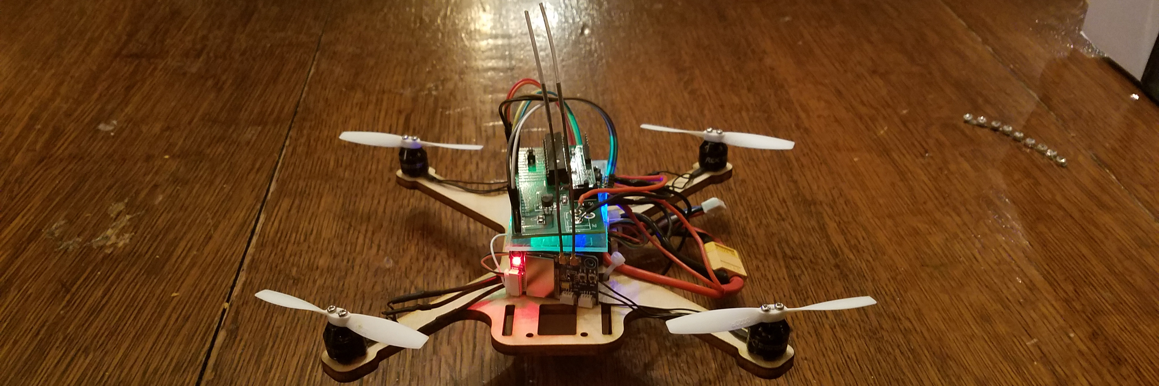
Learn about the project as a whole. High level description of the build.
Fall 2017 ECE4760 Final Project
Using the PIC32 architecture to add autonomous flight capabilities to a simple drone framework; drone flight and control is taken care of by a designated flight controller while the autonomous flight is calculated and executed by the PIC32 microcontroller.
Learn about the project as a whole. High level description of the build.
Learn about the specifics of the project. Dive into the dense "nitty-gritty" of it all.
How did the project perform? What worked and what did not work?
Take a step back and evaluate the end result of the project in more general terms.
The main goal of my project was to add autonomous flight capabilities to a simple drone framework. I have seen many projects in the past which attempt to develop a flight controller for a drone. While the theory behind this is rather simple, it can be hard to acheive great results in practice. Rather than dealing with the PID tuning of flight control, I have chosen to use an existing flight controller to control the drone, while feeding it inputs with the PIC32. In this way, I do not have to worry about stability, but rather can focus on the high level throttle, pitch, roll, and yaw channels.
The original vision was to construct a drone which will follow the user (really a phone) according to GPS data and magnetic heading information. This of course required a base drone framework to run off of. The project could largely be separated into three sections.
This section consisted of designing and building a funcioning drone. At this stage, no autonomy was added. Instead, the drone could be flown and tested using a typical receiver and transmitter.
This section consisted of communicating with the required sensors to receive the necessary data for autonomous flight. In this case, the sensors consisted of a GPS module, magnetometer, and wifi module.
This section consisted of establishing a connection between the PIC32 and flight controller to allow it to fly and operate on its own.
A number of peripherals within the PIC32 were utilized in this project. In particular:
This project was rather ambitious and had many sections which all had to come together, however, it deals with an increasing aspect of today's world; autonomy within robotics. Even more specifically, all sorts of drones (autonomous, hobby, military) have becomre more and more prevelant.
Design and assembly of the main drone framework. Sinple quadcopter using proprietary flight controller.
Operation of stand-alone gps module. Used to establish location of the drone in the world.
Use of magnetic sensor to determine heading of drone. Aids in determination of proper drone control signals
Interface between wifi module, PIC32, and phone app to allow communication between user and phone.
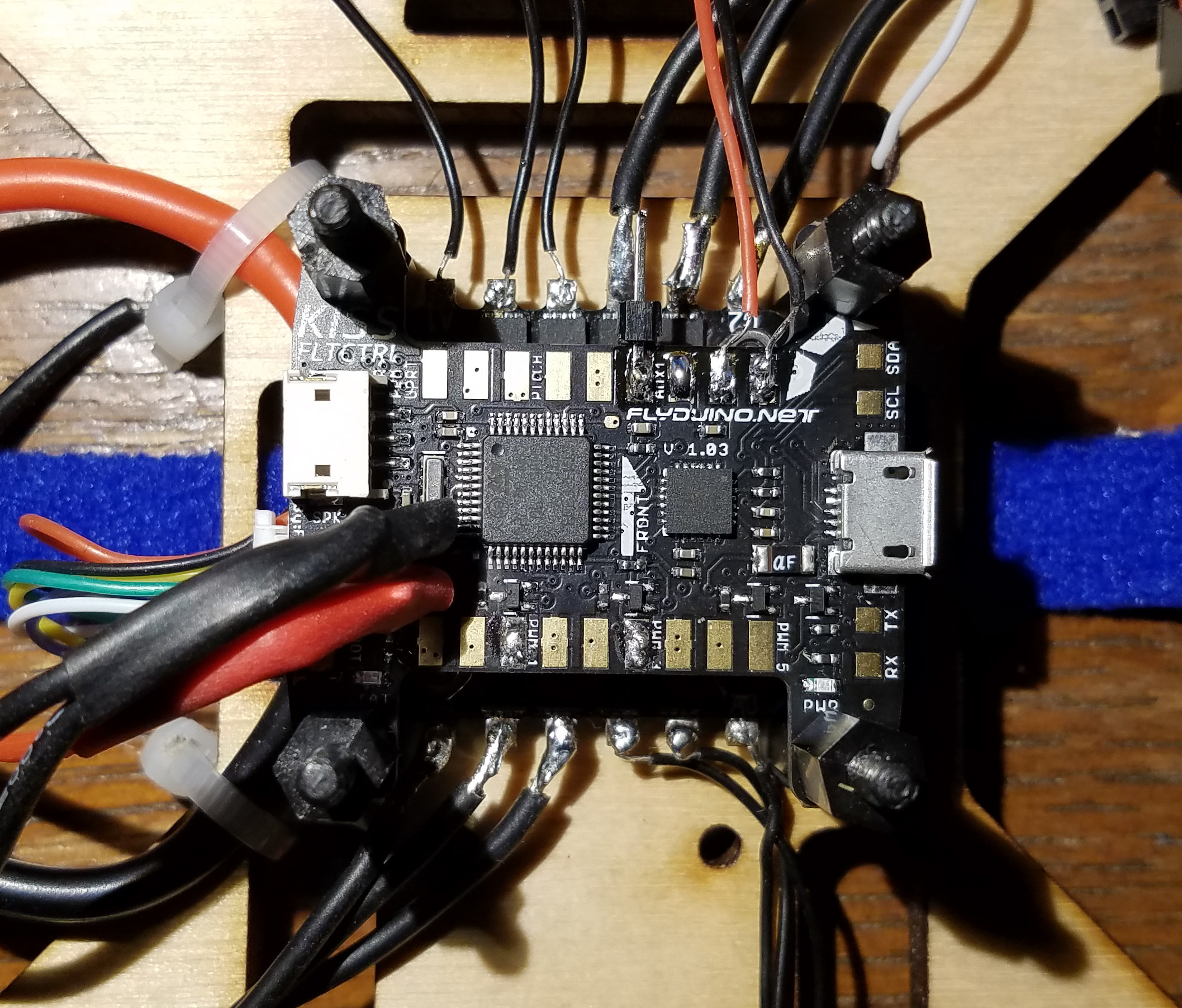
Communication between the PIC32 and the KISS flight controller to allow for control over the drone.
Setup of the PIC32 along with general code (other than communication protocals -> see other sections)
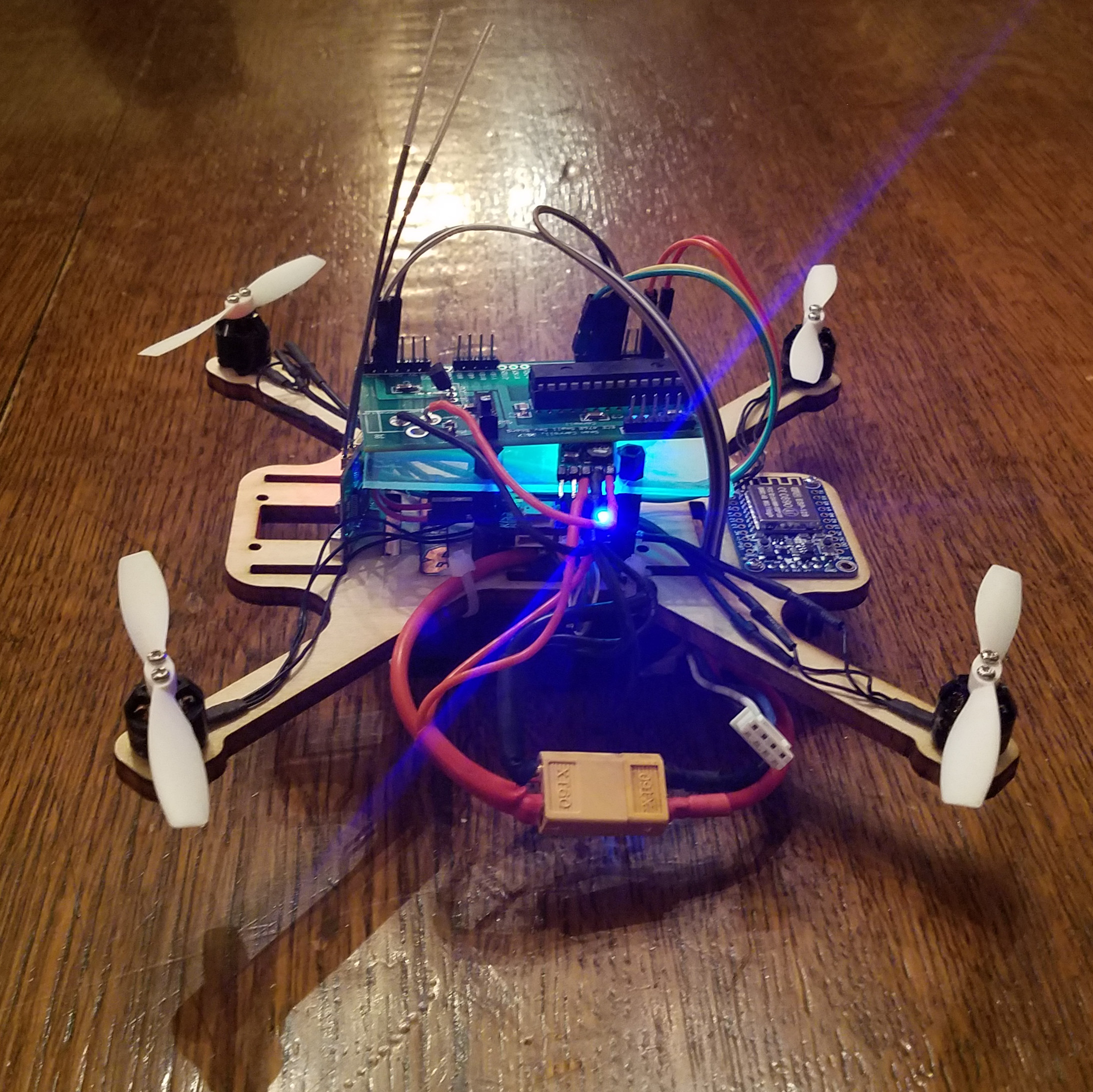
Rather than focusing on the development of a precise flight controller to control the movement of a drone, I chose to extend the functionality of an existing drone. In order to do this, however, I had to have a functioning drone which allows me tap into all of the required signals. I began by looking at the possiblity of just purchasing a solution to the problem. Drones have become more prolific than ever, and it is quite easy to find a decent drone for under $50. The issue is that most of these drones are fully contained. There is very little room for modification if any. Because of this, it became apparent that I would have to build my own drone from various parts. While this provided me with the most flexibility over design, a large part of the project was spent building the actual drone. The rest of this section outlines the various parts of my drone build.
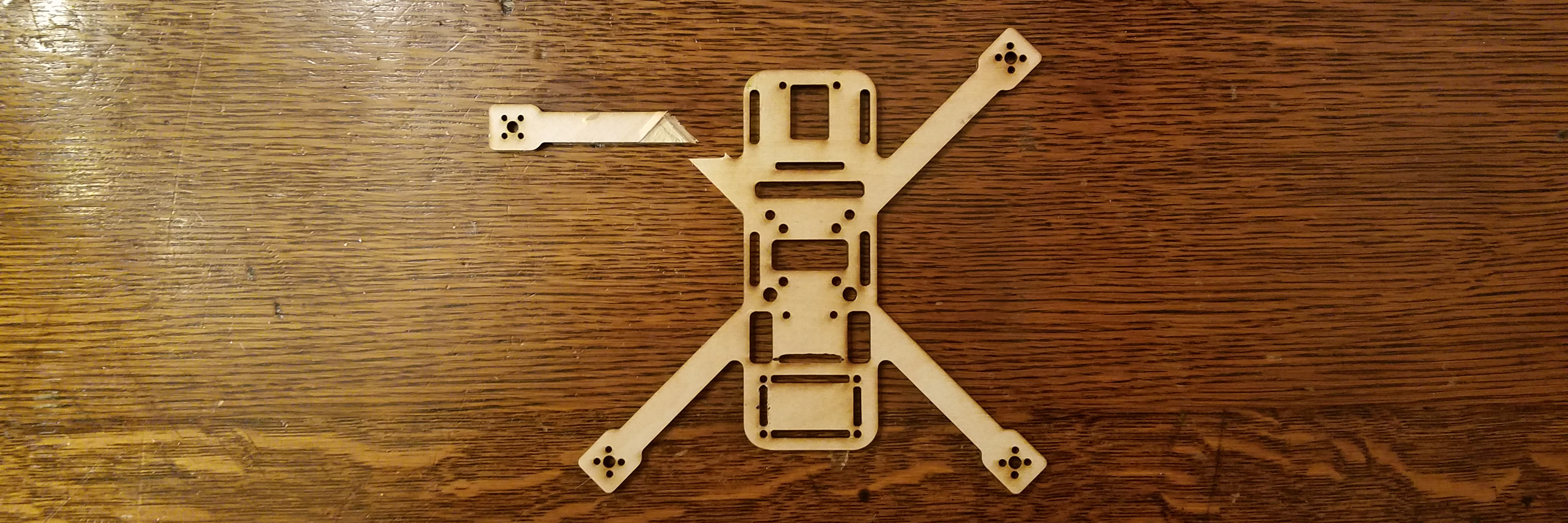
My drone began as some simple sketches in the online CAD tool, OnShape. In designing the frame, I tried to make it as functional as possible for my project. I knew that I would have numerous sensors which had to be placed on the drone in addition to the flight controller. In order to accomodate this, I added mounting holes and cutouts for the main boards. In the center of the drone are two sets of four holes. The inner set is used to mount the ESC, while the outer set are for the flight controller. The flight controller is lifted off of the framework, and sits above the ESC to improve space management. At the front of the drone sits the GPS module. On the other side are the magnetometer as well as the wifi unit at the very end. I also made the frame large enough to eventually support propellers which are up to five inches. Once I had completed the design, I laser cut the frame out of 5mm wood. While this is not the most suitable material for the job, it was easy and allowed for cheap and rapid prototyping. Below are images showing the design of my framework. My design is available for download as a DFI: drone framework
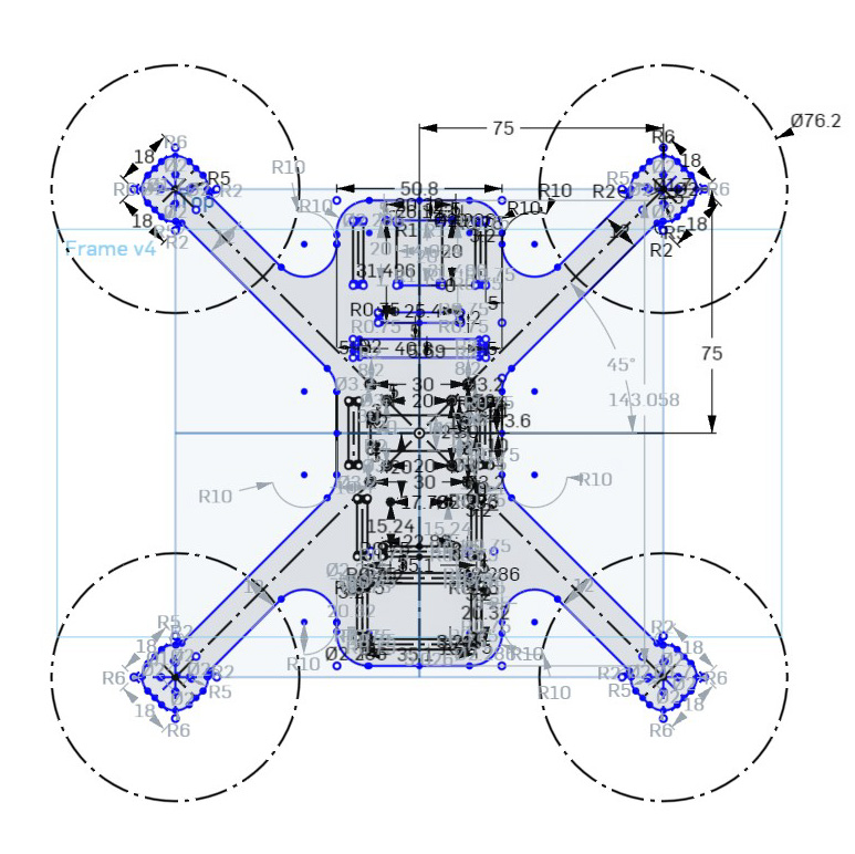 Sketch with constraints
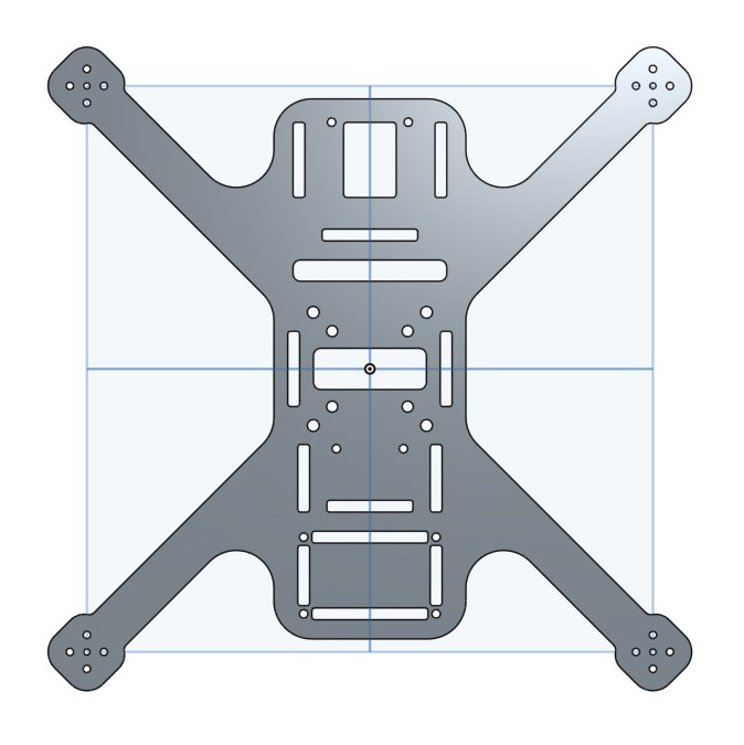 Top view of extrusion
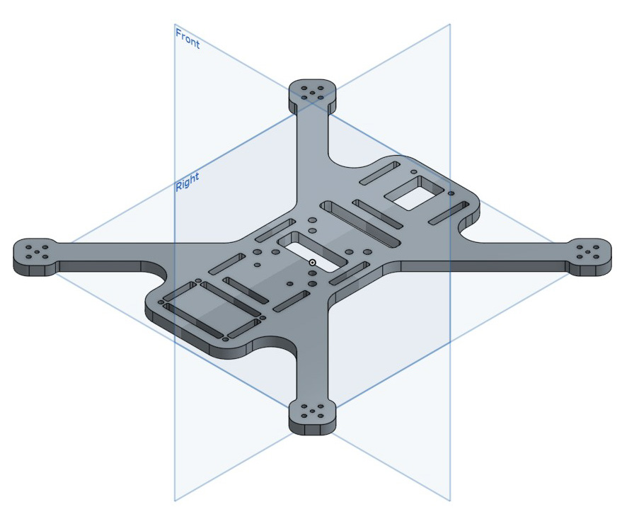 Isometric view of Extrusion
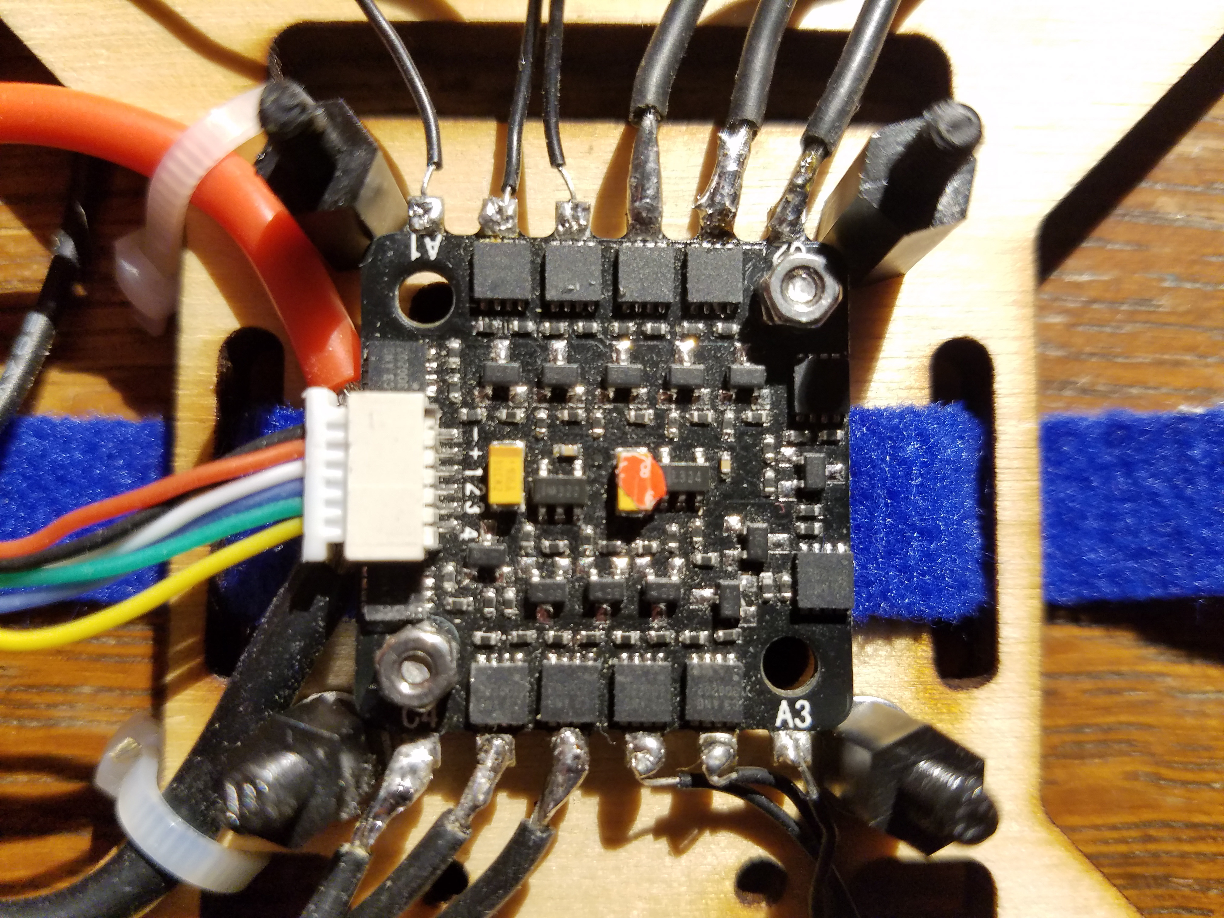
In order to make decisions on movement direction, the drone must have some way of knowing where it is. The most common solution to this is a global positioning system (GPS). From this, the drone can figure out its latitude, longitude, altitude, and even velocity vectors. GPS systems are quite complex themselves, and a lot of development has already gone into them. So much so that you can easily purchase a standalone unit which will provide you with the requested data.
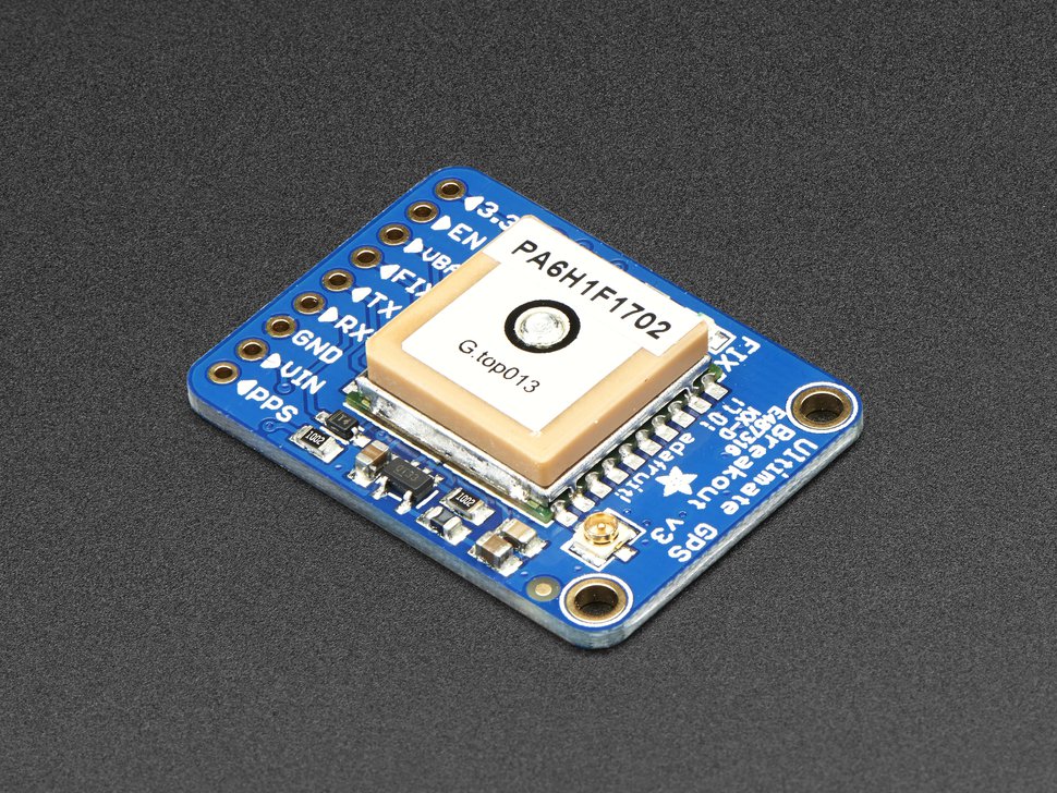
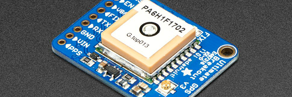
For this project, I chose to use the Adafruit Ultimate GPS Breakout Version 3. This is a breakout board provided by Adafruit, which is built around the FGPMMOPA6H (MTK3339) standalone GPS module. The breakout board provides some very nice extra functionality including:
For my purposes, I did not require many of these extra features, but Adafruit breakout boards are always great to have. As far as the actual GPS module goes, the communication protocal is universal asynchronous receiver/transmitter (UART). After receiving power, the board will begin transmitting with a frequency of approximately 1Hz. Each message is a sequence of ascii characters terminated by a CRLF. Prior to acheiving a FIX, the transmitted data will have no meaning. In messages containing GPS data, the actual values will often be omitted. For further details on the messages see the section on NMEA sentences. Various options regarding the module can be set by transmitting specified sentences to the GPS. For example, the update rate can be changed as well as requesting data on satellites.
NMEA is a specification that defines the interface between various pieces of marine electronic equipment; this includes GPS systems. MTK products have defined a set of NMEA output sentences. The main one I am interested in for this project is RMC. This sentence includes time, date, position, course and speed data and is the minimum recommended navigational information. Once I receive an output sentence from the GPS unit, I need to parse out the required data. Thankfully, Adafruit has developed an C++ library for use with the module. In particular, they have written a NMEA sentence parser which extracts all available data. Although this code is in C++, I was able to transfer most of it into C for use on the PIC32. The core difference was the UART communication between the PIC32 and the GPS module. The Adafruit code can be found here: Adafruit_GPS.
The PIC32 has two UART peripherals, one of which I used to communicate with the GPS module. On startup, I set peripheral pin select to map U1RX and U1TX to physical pins on the PIC32. This is followed by transmitting two messages to the GPS module to set the update rate to 1Hz, and request the minimum location information. My UART receive and transmit functions are similar to those defined by Bruce Land in the protothreads library. Both receive and transmit are actually protothreads to allow other threads to run while we are waiting on data. Because NMEA sentences are ended with CRLF, we continue to read in data until this is found, at which point we zero terminate the character buffer and return. In addition to this, we must continue to check for possible frame errors from the UART peripheral. If a frame error occurs, we discard the current message, and clear the error.
In addition to knowing the location of the drone, you must know the current heading of the drone to be able to navigate in a particular direction. In order to figure out heading, I used a magnetometer to measure the Earth's magnetic field. Using the three coordinate axis, x, y, and z, you can calculate the heading of the sensor based on the magnitude of the magnetic field components.
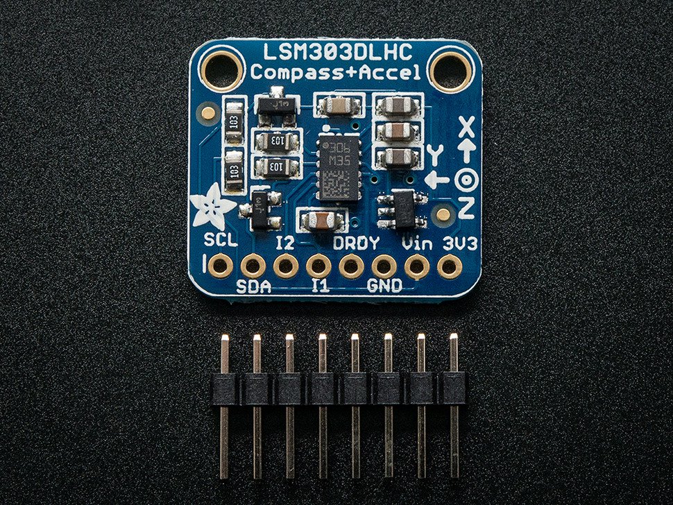
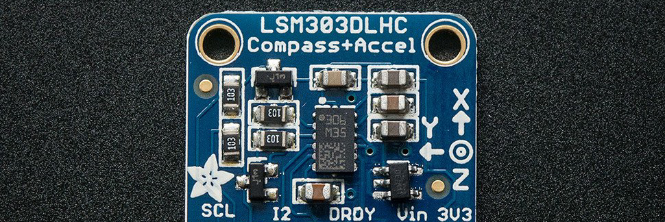
For this project, I chose to use the Triple-axis Accelerometer+Magnetometer (Compass) Board. This is a breakout board provided by Adafruit, which is built around the LSM303DLHC magnetometer + accelerometer sensor. The breakout board provides some very nice extra functionality including:
The sensor itself uses I2C communication protocol to send and receive data. Because I2C is highly dependant on the specific device, it was important to read the documentation for the LSM303DLHC.
The PIC32 has two I2C peripherals, one of which I used to communicate with the magnetometer sensor. In order to use I2C communication, you have to open the peripheral by setting certain control registers. Using plib, this is as easy as a call to OpenI2C1( I2C_EN, BRG_VAL );. The SCL and SDA signals are connected to pins RB8 and RB9 on the PIC32. Once the module was initialized, I defined two helper functions for reading and writing data.
First, void i2c_write(char address, char sub_address, char *data, int num); takes in an 8 bit address, an 8 bit sub-address, a pointer to a character, and an integer number. The address information is used to select the proper device to communicate with. The data is treated as an array with the data to send. The number of bytes to send is defined by the final parameter num. To start, the address is OR'ed with the write signal, 0b00000000. This along with the sub_address is considered as the header. This is sent followed by the correct number of bytes from the array data.
Next, I defined a read function void i2c_read(char address, char sub_address, char *data, int num);. This function takes the same parameters as the write function. The 8 bit address and sub-address are treated the same, but know the bytes are read into the data array starting at data[0]. The parameter num is the number of bytes to read into the array. Reading data is slightly more involved than writing data using I2C. To start, the address is OR'ed with the write signal, 0b00000000. The sub_address is OR'ed with the auto increment signal, 0b10000000. Note, the auto increment functionality allows you to read multiple sequential sub-addresses in a row. This is most likely dependant on the specific device you are using. The two addresses are used as the header, and are written to the SDA line. Once the header is written, the restart signal is sent, and the same address is sent with a read signal attached, 0b00000001. Finally, following this we can read the requested data into the array.
I2C is highly dependant on the specific device you are trying to communicate with, therefore, it is important to note some specifics of communicating with the LSM303DLHC sensor. To begin, the breakout board from Adafruit has integrated pull-up resistors, so I could simply connect the SCL and SDA signal wires directly from the PIC32. In addition, Adafruit has developed a C++ library to use in conjunction with this sensor. I converted a large portion of this library to be compatible with the PIC32. In particular, the header file contains all of the required addresses and sub-addresses when using this sensor. The Adafruit code can be found here: Adafruit_LSM303DLHC. In order to begin receiving magnetic data from the sensor, some control registers must first be set. Setting the MR_REG_M register to 0x00 enables continuous conversion mode for the magnetic sensor. Next, setting the CRA_REG_M sets the minimum update rate for magnetic data. This can range between 0.75Hz and 30Hz. Lastly, I set the magnetic gain to a known value. Following this setup, I can now read data from the module. Although I did not implement this, it would not be too difficult to extend the code to read new data on every positive edge of DRDY. On the PIC32 this can be done using a change notice interrupt on a specific pin.
In order to calculate the angle heading of the sensor, you need the x and y magnetic field magnitudes. Using simple trigonometry, the heading is float heading = atan2f(y, x);. This result is returned in radians in the range -pi to pi. Therefore, it must be converted to degrees, and adjusted to range from 0 to 360.
The last set of information that the drone must know in order to autonomously follow is something to follow. In this case, that will be a GPS signal from a phone. This requires some way for the drone to communicate with the phone. Bluetooth is a generally easy to implement but the range is not great. Because of this, I chose to use wifi to communicate with the drone remotely. In addition to sending GPS coordinates, I can send other control signals to the drone to change its flight.
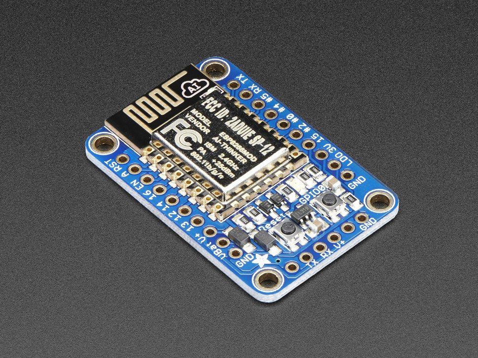
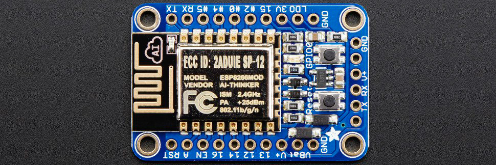
For this project, I chose to use the Adafruit HUZZAH ESP8266 Breakout. This is a breakout board provided by Adafruit, which is built around the ESP8266 processor. This process is an 80 MHz microcontroller with a full WiFi front-end (both as client and access point) and TCP/IP stack with DNS support as well The breakout board provides some very nice extra functionality including:
The module itself uses UART communication protocol to send and receive data.
The ESP8266 module can be used for a range of jobs and can be configured in many different ways. For my purpose, I simply wanted the device to act as a soft api to allow my phone to connect to its wifi. From here, I can open a TCP connection and send data to the module. As the last step, the data can be transmitted from the ESP8266 to the PIC32 using serial communication. In order to program the wifi module, I used the Arduino IDE. Configuring a soft api is as simple as a single function call, IPAddress myIP = WiFi.softAPIP();. Once this setup is successful, the host waits for a client connections. Once a connection is established, the server waits to receive data. When the line end is received, the data is serial transmitted from the TX pin.
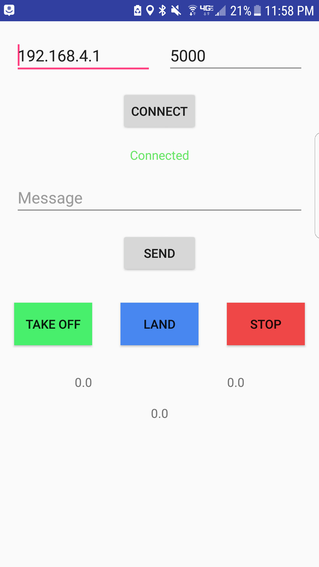
On the backend, the app will establish and maintain a TCP connection to the provided IP address and port number. When data is ready to be sent, it is written to the data stream, and received by the wifi module.
The PIC32 has two UART peripherals, one of which I used to communicate with the wifi module. On startup, I set peripheral pin select to map U2RX and U2TX to physical pins on the PIC32. My UART receive and transmit functions are similar to those defined by Bruce Land in the protothreads library. Both receive and transmit are actually protothreads to allow other threads to run while we are waiting on data. Because all of my transmitted messages are ended with CRLF, we continue to read in data until this is found, at which point we zero terminate the character buffer and return. In addition to this, we must continue to check for possible frame errors from the UART peripheral. If a frame error occurs, we discard the current message, and clear the error.
In order to actually control the drone, the PIC32 neeeds some way to communicate and send signals to the flight controller. This is where you really have to dive deep into the documentation of both the PIC32 and KISS flight controller to find a solution that works. Almost all current flight controllers will support multiple forms of communication as there are a range of different receivers on the markert since each one has its advantages over the other.
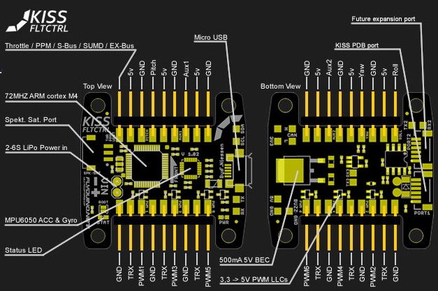
In general, most current drones rely on some form of serial communication with the receiver. For example, PPM acts as a summed PWM signal to support eight channels on a single wire. These protocols greatly reduce the complexity of the hardware since there is only a need for one signal wire in addition to ground and Vcc. Also, a larger number of channels can be supported than a protocol such as PWM for example which requires one input pin per channel. With all of these advantages, it might seem crazy for me not to go with a serial based communication protocol, however, that is exactly what I did. In particular, I used parallel PWM. Each channel has its own Pulse Width Modulated (PWM) signal on an individual wired connection. Most flight controllers including the KISS will support up to six channels using PWM (Pitch, Roll, Throttle, Yaw, Aux1, Aux2). The main driving factor behind choosing this protocol was the need for a killswitch. In trying to control the drone autonomously, I have very little control over its actions. If the PIC32 sends a throttle signal that is a little to large, I can easily lose my project off into the sky. Because of this, I needed some way to add a killswitch. The easiest way to add a killswitch is to use a standard drone receiver and transmitter. This functionality is often done in this way, and is easily supported on most frameworks. this difficulty with this is that it might be difficult or even impossible to use two different communication protocols on the flight controller. The advantage of PWM is that I have multiple signal wires. In this way, I can have the four main control signals (Pitch, Roll, Throttle, Yaw) controlled by the PIC32, and one of the other auxillary channels controlled by a PWM based receiver.
The image to the right is the receiver I used for this project. It supports PWM, PPM, and i-BUS. The eight wire connector in the bottom left of the image is the PWM bus. This can also be seen on the pinout to the left. For my purposes, I only needed three wires from the receiver; Vcc GND and one of the channels. For the specific channel, I chose to use channel 5. Generally, the first four channels are used for Pitch, Roll, Throttle, and Yaw, and five and six are auxillary channels. In conjunction with this receiver, I borrowed a Flysky transmitter from a friend, and set channel five to be controlled by one of the switches. Once I wired the channel 5 output from the receiver to aux1 PWM input on the KISS, I could receive the proper kill signal.
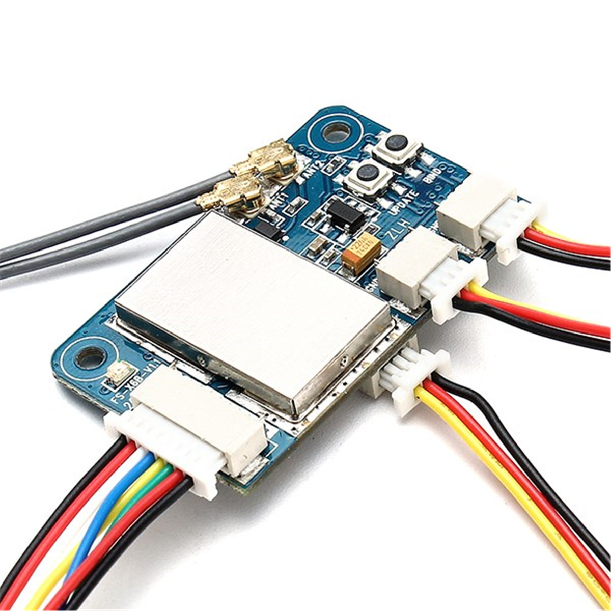 Flysky X6B 2.4G 6CH i-BUS PPM PWM Receiver
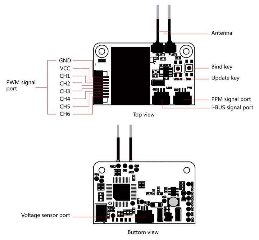 Flysky X6B Pinout
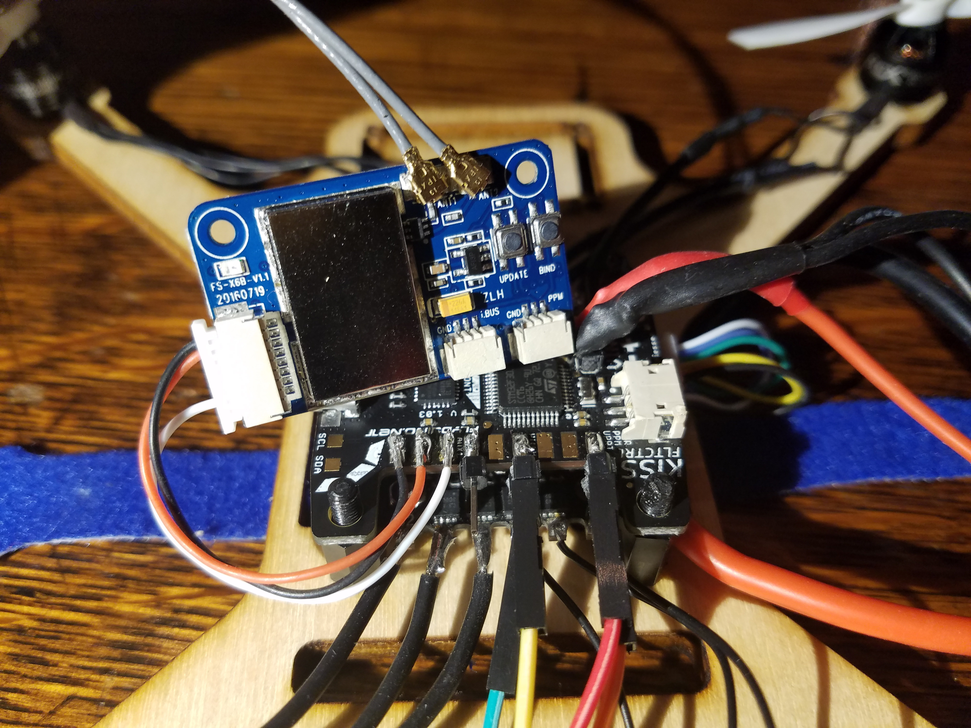 Receiver Connections
In order for the PIC32 to control the drone, I had to generate PWM signals for each channel I would like to affect. For this project, I control Pitch, Roll, Throttle, and Yaw using four separate PWM signals from the PIC32. In Betaflight you can change various minimum and maximums regarding the input pulses, but most signals will follow a fairly common standard. Betaflight defines two constants, rx_min_usec = 885 and rx_max_usec = 2115. These define the minimum and maximum pulse lengths in microseconds which are considered valid by the flight controller. However, in general most signals will range between 1000 and 2000 microseconds. In my PIC32 code, I limited my pulse lengths to fall within this range. As far as the frequency of the PWM pulse train, almost any frequency is acceptable. Many receivers seem to use a frequency of 50 Hz. This is rather slow, and a large clock divider is required to acheive this frequency. The increased clock divider decreases the resolutin of the pulse length giving you less ability to make fine adjustements. Because of this, I increased my frequency to 200 Hz. This can be achieved using a peripheral bus clock of 40 MHz, a clock divisor of 4, and a timer counter of 50000. Then, in theory, the pulse width in microseconds will be pulse_width_value / 10. The image to the left is a trace of one of the PWM signals. This particular pulse train has a pulse width of 1500 microseconds, which is defined as mid_rc in Betaflight.
Once I was able to generate the proper PWM signals, I tried to pass them to the KISS flight controller. In working on this, I encountered a few interesting bugs. First, all channels have a defined fail mode defined as rxfail in Betaflight. By default, the first four channels are set to automatic failsafe mode. In this case, when the signal data is not within the valid range, the channel defaults to a particular value. For Pitch, Roll, and Yaw this default value is mid_rc, while Throttle defaults to rx_min_usec. The auxillary channels default to a different failsafe mode, hold. In this mode, when an invalid signal is received, the last valid value is used. In order for the PIC32 signals to be properly received, the channels must be in hold mode. Once I changed this for the first four channels, the PIC32 signals could be seen in the receiver tab of Betaflight.
The next issue I encountered was the mapping from the KISS' PWM input pads was different from the internal pin mapping. For example, the solder pad labeled as Throttle on the KISS affected the Pitch value in Betaflight. This is not a critical issue as I just need to know the correct mapping, but there is a fix to map the corresponding pads with their signals. In Betaflight, you can change the channel mapping. The two main provided mappings are AETR1234 and TAER1234. For the KISS, the mapping must be changed to 1TAER234 to match the solder pads. Once I had these issues fixed, I wired up all of the signals including the auxillary receiver channel and tried to arm the flight controller. A few notes must be made about arming as I encountered issues. First, I defined a range of values for channel 5 which would arm the flight controller. Even if this is satisfied, the flight controller might not arm. First, the Throttle must be below a certain value. In Betaflight, this is defined as min_check, and was set to 1100. In order to fix this, I set the Throttle channel output from the PIC32 to rx_min_usec. In addition to this, if any of the first four channels are not receiving valid data, it will not arm. There are some other small reasons why it might not arm. If the cpu load is too high, you have to decrease it by decreaseing the PID loop. Also, you might have to calibrate the accelerometer or ensure the flight controller is sitting stable on a level surface. Once I had satisfied all of the requirements, I was able to arm the flight controller. Taking the propellers off of the motors, I tested the communication between the PIC32 and flight controller. Once the flight controller was armed, I could increase the speed of the motors by adjusting the Throttle PWM.
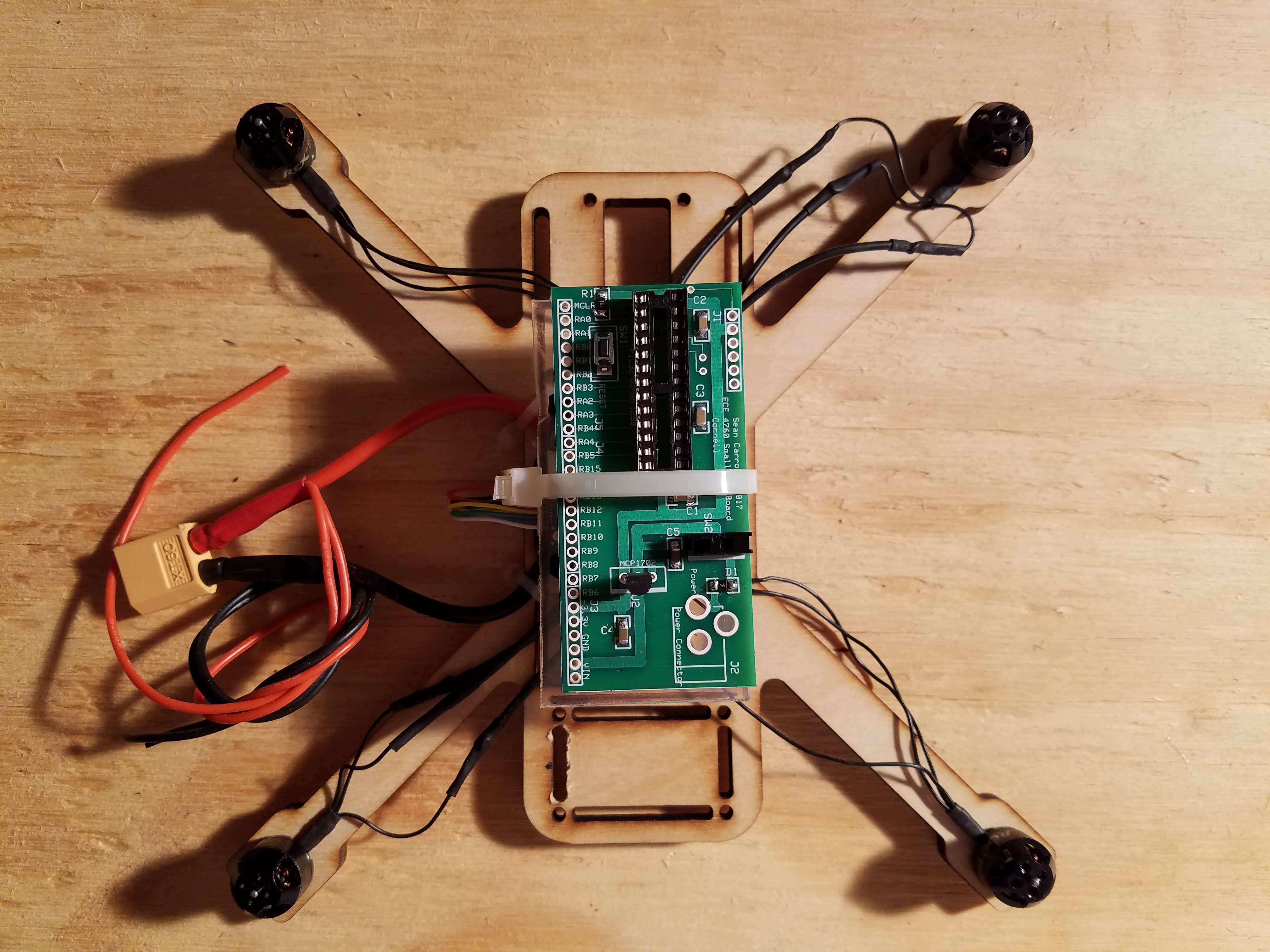
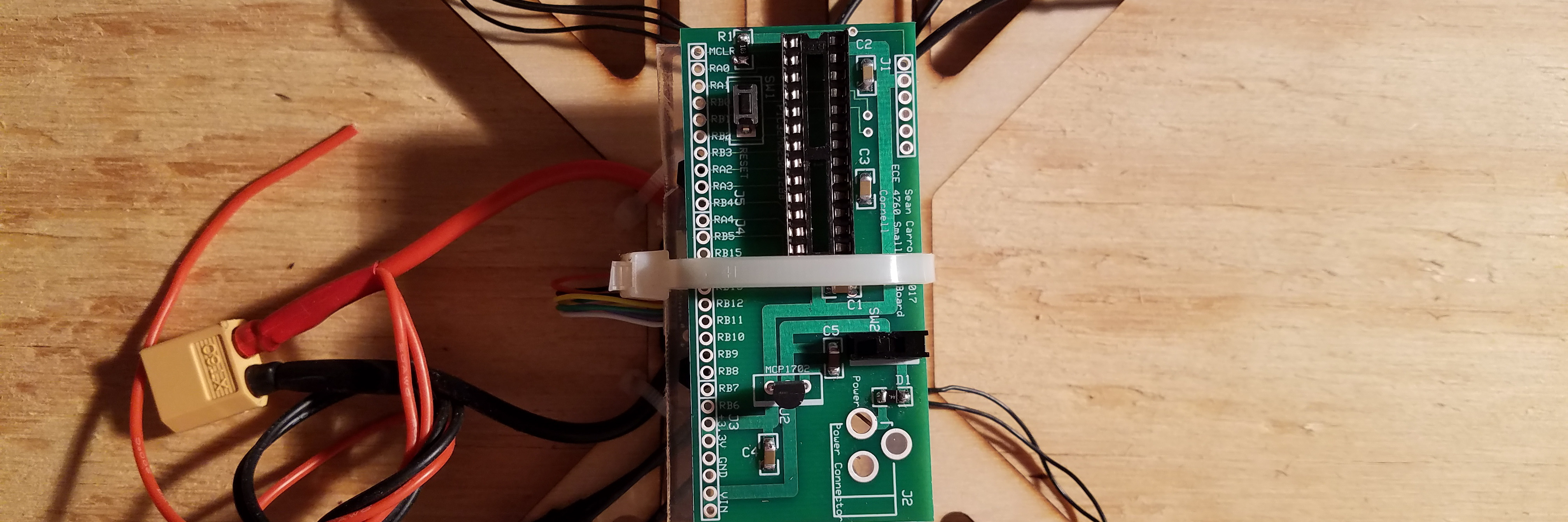
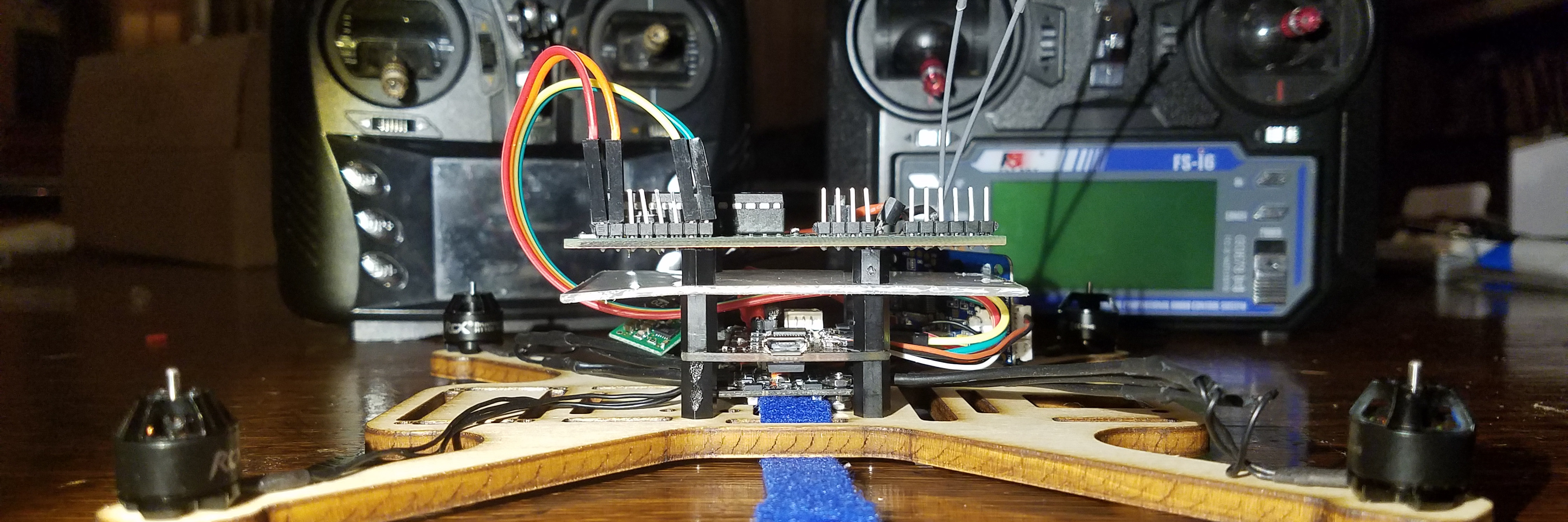
A lot of consideration had to go into the setup and wiring of the PIC32. Trying to make an autonomous drone, the PIC32 must be attached to the drone and be able to operate on whatever power is provided. I went through a couple different design choices and ultimately settled on a solution which works well. In addition to the physical setup, I had to develop code which would work in the new environment.
After the PIC32 was wired up to get power, I could begin wiring the signal connections. RA0, RA1, RA2, and RA3 were used as PWM channels for the flight controller. The KISS can recognize 3.3 V logic, so these signals did not have to be changed and could passed straight to the flight controller. I did not have to add a ground connection between the PIC32 and KISS since they already have a shared ground from the battery. Each of the extra modules (GPS, Compass, wifi) required at minimum four connection to the PIC32. Power and ground could be jumped from the PIC32 development board. Because each breakout board has its own voltage regulator, any of them can receive 5V or 3.3V. In addition to this, both communication protocols I used require to connections. For UART, I connected the TX and RX pins to the opposite one on the other device. For I2C, I connected the SCL and SDA lines.
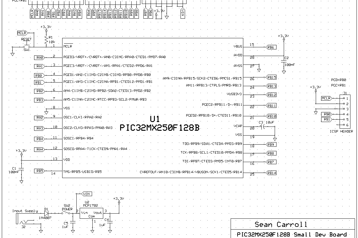
Here is a full circuit schematic for the drone I built.
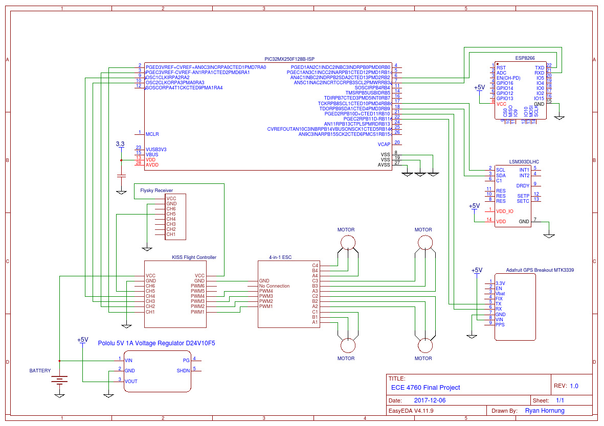 Full Circuit Schematic
This project required a lot of software to communicate with the various peripheral devices. First, two UART peripherals were used to communicate with the GPS and wifi units. The description of these can be found in their respective sections. At a high level, I had two protothreads which continue to read in data and update global variables with the parsed information. This is also done with the magnetometer, but the communication protocol is I2C rather than UART.
For the PWM signals, I used four different output compare units. These were rather easy to configure. On startup, I open the modules, and initialize them with a default value. For pitch, roll, and yaw this value was mid_rc whereas for throttle this value defaulted to 1000 microseconds. The flight control was then updated in a timer interrupt service routine. Timer 2 is setup to run at 100Hz. On each pass through, the PWM width is adjusted to fly the drone.

I began by assembling and testing the drone framework. In order to add any autonomous flight, I had to ensure I had a solid basis. This started in Betaflight. Once I had the flight controller and ESC wired together and to the motors, I could perform a motor test in the GUI. Increasing the power to each motor, I could figure out my mapping and rotation. Luckily all of my motors were set up perfectly. I did not have to remap anything, or change the direction of rotation.
Following this, I added a small serial base receiver to test the flight of the drone with a transmitter. This behaved as expected and was quite a large milestone. Seeing drone fly, even if being controlled was a large part of the project.
Next, I had to ensure I could control the flight controller with the PIC32. After setting up the code to generate the PWM pulses and wiring the connections to the flight controller, I tested the signals in the Betaflight GUI. In the receiver tab I could see changing signals as I changed the PWM pulse width. There is a video in the videos section showing my testing of the killswitch. This was highly dependant on the flight controller receiving proper signals.
Once I had all of the code to receive data from the GPS, compass, and wifi modules, I tested it using the big development board. Using the big board, I could display the messages being received on the TFT display and ensure the data make sense.
After testing the previous sections, I could finaly test the drone running from the PIC32. I did this by arming the drone and increasing the throttle to get the drone to fly up. Initially, I was highly dependant on the killswitch as I was investigating various throttle values. After the first few values barely lifted the drone off of the ground, I increased the throttle to a fairly large value. When the drone finally took off, it shot up to the ceiling of the room. I hit the killswitch right away, and managed to catch the drone. Thankfully, the only damage to the drone were a few bent signal pins. After fixing this, I continued to play with the control values. Taking the drone outside for one flight, it ended up getting too high and too far away. I had to hit the kill switch, and the drone crashed to the ground. Once of the drone arms broke, and I had to quickly cut a new frame and transfer all of the hardware. After fixing the drone, I resumed testing, and it behaved as expected.
In testing the flight of the drone, it became apparent that it is very difficult to maintain a constant altitude. Typically, drones will use sonar, or a barometer to acheive altitude hold. While it is possible to add one of these to my drone build. There was next to no documentation with the flight controller I used. Because of this, I resolved that it would take more time than I had and decided not to pursue it further. Without an easy way to perform altitude hold, it was difficult to work on a following algorithm. Although I had developed communication with the GPS and compass modules, I decided not to include them in the final build.

The initial goal of the project was quite ambitious. While the final result did not demonstrate truly autonomous flight, I did manage to control a drone using an onboard PIC32 microcontroller. This really is the hardest part of the goal. Once I am able to control the drone, it is only a matter of sending the proper control signals.
The GPS unit used in this lab utilizes NMEA output sentences. This standard was developed for use with marine electronic equipment.
I used the UART communication protocol to receive and transmit information with two separate modules. Much of this was taken care of by the PIC32, as it has existing UART peripherals.
I used the I2C communication protocal to receive and transmit information with the magnetometer sensor. Much of this was taken care of by the PIC32, as it has existing I2C peripherals.
Some portions of this project were adapted from existing code. For the GPS and magnetometer, my code was based on Adafruit libraries. The corresponding code has been linked and referenced accordingly. In addition to this, Betaflight was used to configure the drone's flight controller. Betaflight is open source software and also has bee linked in the appendix.
There are no legal considerations for this project as far as I know.
In designing and building this project I kept in mind the IEEE Code of Ethics to ensure that all users would be safe from harm. Drones are not the safest devices and can often behave sporadically. Especially when attempting to add autonomous flight. Becuase of this, I made sure to add a reliable killswitch. Arming and disarming a drone using a transmitter is the standard way to do this, and it provided a consistent and safe way to shut off the drone. When testing the drone flight, I made sure I was in a clear area and away from people. Any people around my area had to know about the drone prior to my testing.
This video shows the process of controlling the flight controller with PWM signals. The first four channels are controlled with PWM signals from the PIC32. Pitch, Roll, and Yaw are set to mid_rc while Throttle is set to 1000 microseconds. Channel aux1 is controlled by the extra PWM receiver. As the switch on the transmitter is toggled, the flight controller will arm and disarm. As an extra visual aid, when the Betaflight is not available (anytime during actual flight), the blue LED on the flight controller acts as a status signal. When the LED is solid blue, the flight controller is receiving valid signals, but is not currently armed. Upon arming, the LED turns off. When the flight controller is not receiving valid signals such as when the PIC32 is off and is not sending PWM signals, the LED will blink with a frequency of approximately 1Hz.

The group approves this report for inclusion on the course website.
The group approves the video for inclusion on the course youtube channel.
| Part | Unit Cost | Number | Total Cost |
|---|---|---|---|
| KISS Flight Controller | 20.00 | 1 | 20.00 |
| 4-in-1 ESC | 20.00 | 1 | 20.00 |
| RCX H1105 Motor | 11.00 | 4 | 44.00 |
| Flysky X6B Receiver | 10.00 | 1 | 10.00 |
| Adafruit HUZZAH Breakout Board | 10.00 | 1 | 10.00 |
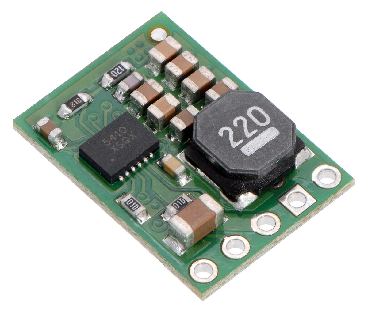
| Pololu 5V 1A D24V10F5 | 8.00 | 1 | 8.00 |
| Small Board | 4.00 | 1 | 4.00 |
| PIC32 | 5.00 | 1 | 5.00 |
| Jumper Cables | 0.10 | 8 | 0.8 |
| 121.8 | |||
I was a one person group so the entirety of the project was completed by me.
I would like to give a special thanks to Jeff Hornung and Adam Weld. Jeff provided valuable support helped in the high level design of the project. Adam expertise with drones was invaluable to helping me build a working drone.