The primary purpose of our system’s software is to analyze the EMG signal from the player’s leg and convert this to a control signal for the robotic leg. We accomplish this by inputting the envelope of the incoming EMG signal to our microprocessor and triggering a kick when the envelope exceeds a threshold.
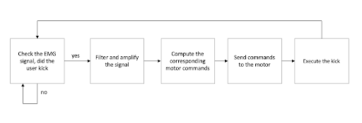
Block Diagram of our Game's software implementation
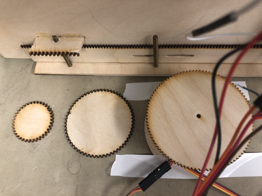
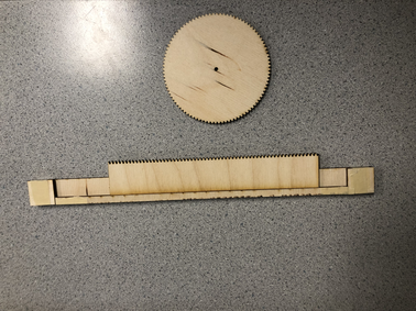
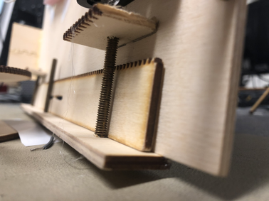
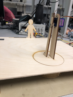
Servo Control
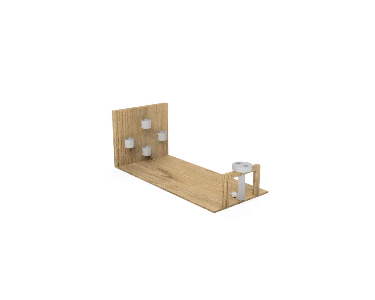
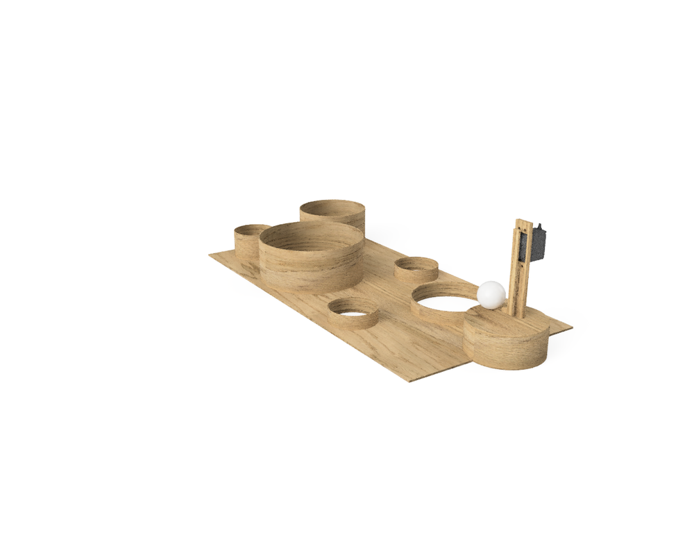
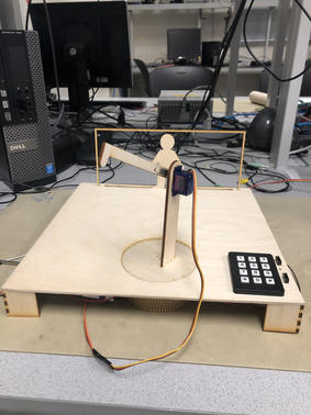
Our system utilizes three fixed-rotation servos to control our game's moving elements. In addition to controlling the pitch of the robotic leg, fixed-rotation servos are used to control the rotation of the stand the leg rests on, and the position of the goalkeeper.
These servos are capable of rotating +/- 90° from their center point. Their angles are controlled by 50 Hz PWM signals, the duty cycles of which set each servo's desired angle. According to the datasheet, a 1 ms pulse should set one such servo to its minimum angle and a 2 ms pulse should set it to its maximum angle. In practice, we found that that 0.6 ms and 2.4 ms pulses were required to reach these extreme angles.
Waveform Generation
Our system uses the PIC32's output compare modules to generate the PWM waveforms used to control its fixed rotation servos.
First, we set Timer 2 to continously trigger at 50 Hz. Our system operates at 625 KHz, so a period of 12500 clock cycles is selected to achieve this frequency.
//set period to generate wave of 50Hz
        #define generate_period 12500
        OpenTimer2(T2_ON | T2_SOURCE_INT | T2_PS_1_64, generate_period-1);
Next, output compare units 1, 2, and 3 are initialized to use timer 2 as a source. These units are set to go high for OC1_width, OC2_width, and OC3_width clock cycles at the beginning of a period, and then to remain low for the rest of each period. OC2_width and OC3_width are initialized to 938 clock cycles, or 1.5 ms, so as to drive each servo to its central angle. Similarly, OC1_width, representing the pitch of the robotic leg, is set to 1250 clock cycles, or 2.0 ms, to drive the leg to its maximum backward position. Subsequently, Each output compare signal is outputted to one of the PIC32's output pins.
OpenOC3(OC_ON | OC_TIMER2_SRC | OC_CONTINUE_PULSE , OC3_width, 0);
        // OC3 is PPS group 4, map to RPB9
        PPSOutput(4, RPA3, OC3);

        OpenOC2(OC_ON | OC_TIMER2_SRC | OC_CONTINUE_PULSE, OC2_width, 0);
        // OC2 is PPS group 2, map to RPB5
        PPSOutput(2, RPA1, OC2);

        OpenOC1(OC_ON | OC_TIMER2_SRC | OC_CONTINUE_PULSE, OC1_width, 0);
        // OC1 is PPS group 1, map to RPB3
        PPSOutput(1, RPB3, OC1);
A thread used to control these PWM signals runs once every 20 ms, adjusting the pulse width of the output compare signals. The code used in this thread to adjust the signals that control the position of the goalie and the rotation of the robotic leg is shown below:
if (pulse_factor_goalie >= 2.4 || pulse_factor_goalie <= .6){
            pulse_increment_goalie *= -1;
            pulse_factor_goalie += 2*pulse_increment_goalie;
        }
        pulse_factor_goalie += level*pulse_increment_goalie;

        OC2_width = (int) (pulse_factor_goalie*min_pulse);
        CloseOC2();
        OpenOC2(OC_ON | OC_TIMER2_SRC | OC_CONTINUE_PULSE , OC2_width, 0);

        if (pulse_factor_player >= 2 || pulse_factor_player <= 1){
            pulse_increment_player *= -1;
            pulse_factor_player += 2*pulse_increment_player;
        }
        pulse_factor_player += level*pulse_increment_player;

        OC1_width = (int) (pulse_factor_player*min_pulse);
        CloseOC1();
        OpenOC1(OC_ON | OC_TIMER2_SRC | OC_CONTINUE_PULSE , OC1_width, 0);
Here, pulse_factor_goalie and pulse_factor_player are variables representing the duty cycles (in ms) of the waveforms used to control the goalie's position and the rotation of the robotic leg, respectively. At each 20 ms step, these values are incremented or decremented by a factor level*pulse_increment, effectively sweeping the duty cycle of these waveforms, and in turn, the positions of their associated servos between two extreme values.
A plot representing these signals is shown below. In each case, the rate at which the signals increment is increased by a factor of ten and the pulse width of the signals is doubled, so as to better illustrate their behavior.
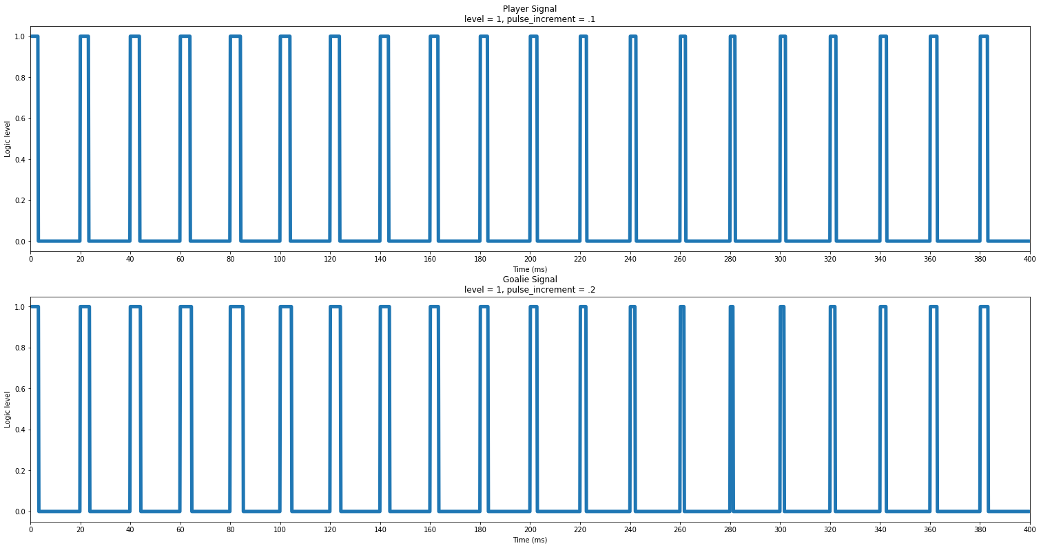
Visualizations of pulse_factor_player and pulse_factor_goalie over time
Video of player rotation and goalie movement
Player Input
In the PWM control thread, the value of the muscle sensor envelope is read from the PIC32's ADC and used to control the pitch of the robotic leg.
The following snippet is used to obtain the value at the ADC in volts:
adc_9 = ReadADC10(0);
        AcquireADC10();
        V = (float)(adc_9 * 3.3 / 1023.0) ; // Vref*adc/1023
If this value remains above a certain voltage for 2 iterations of the PWM control thread, the system determines that the player intends to kick the ball, and sets OC3's duty cycle to 1 ms, effectively causing the robotic leg to kick. Otherwise, OC3's duty cycle is set to 2 ms, its maximal backwards position.
if (V <= 2.5) {
            OC3_width = max_pulse;
            counter = 0;
        }
        else {
            if (counter < 1){
                counter += 1;
            }
            else {
                OC3_width = min_pulse;
            }
        }
A plot representing the interaction between the EMG input and the PWM signal controlling the robotic leg is shown below. Again, the pulse width of PWM signal is doubled, so as to better illustrate its behavior. As you can see, the PWM signal's duty cycle is set to its minimal value after the EMG input is detected to be above 2.5 V for at least 60 ms, resetting when the signal settles below this level.
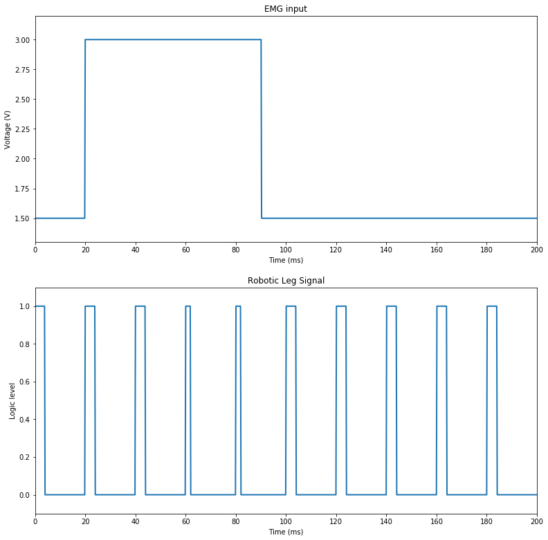
Visualization of robotic leg control signal in response to user input
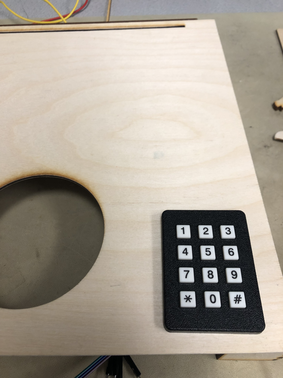
Difficulty Settings and Keypad Input
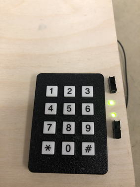
A user can adjust the difficulty of our game using a 3x4 telephone style matrix keypad. By pressing different keys, the user can control our system's level parameter, in turn affecting the speed at which the goalie moves and the velocity with which the pedestal that the robotic leg rests on rotates.
When a keypad input is registered, the value of the key pressed is used to select the value at the corresponding index of the leveltable array shown below, in turn setting the level parameter to this value. For example, by pressing the "0" key, a user selects a level value of .5, effectively setting the game to run at 1/2 of its default speed. The "*" and "#" keys are taken to represent 10 and 11, respectively.
   static float leveltable[12]=
            {0.5, 0.583, 0.666, 0.75, 0.833, 0.916, 1, 1.083, 1.166, 1.25, 1.333, 1.416};
A schematic of the keypad is shown below:
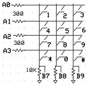
3x4 matrix keypad schematic
Keypad input is handled in its own thread which runs every 50 ms. On each iteration of this thread, our system drives A0, then A1, then A2, and finally A3 to a low voltage, keeping the others high. For each such write, the voltages at B7, B8, and B9 are read. If one of these reads contains a low value on B7, B8, or B9, it will uniquely identify which button has been pressed. The code that accomplishes this is shown below:
char out_table[4] = {0b1110, 0b1101, 0b1011, 0b0111};
        #define no_button (0x70)

        for (i=0; i<4; i++) {
            start_spi2_critical_section;
            // scan each row active-low
            writePE(GPIOZ, out_table[i]);
            //reading the port also reads the outputs
            keypad  = readPE(GPIOZ);

            end_spi2_critical_section;
            // was there a keypress?
            if((keypad & no_button) != no_button) { break;}
        }
As an example, if "6" is pressed, B7 will read low when A1 is written high. In this case, when the input port is read, [A3 A2 A1 A0] will read 0b1101 = 0xD and [HIGH B9 B8 B7] will read 0b1110 = 0xE. As such, the value of the read will be 0xED, uniquely identifying the keypress as "6". The code used to accomplish this identification is shown below, where i will take the value of the key that has been pressed, or -1 if no key has been pressed:
int keytable[24]=
        //        0     1      2    3     4     5     6      7    8     9    10-*  11-#
                {0xd7, 0xbe, 0xde, 0xee, 0xbd, 0xdd, 0xed, 0xbb, 0xdb, 0xeb, 0xb7, 0xe7}


        for (i=0; i<12; i++){
            if (keytable[i]==keypad) {
                break;
            }
        }
        // if invalid or two button push, set to -1
        if (i==12) i=-1;
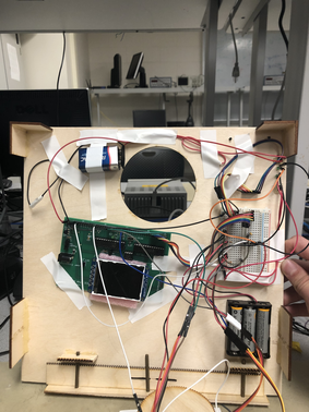
Power Routing
For safety reasons, the muscle sensor used in our system must remain isolated from the electrical grid. As such, our system is primarily powered by batteries. The PIC32 microcontroller used to control the system is powered by a 9 V DC battery, while the system's servos and the EMG muscle sensor are powered by 3 AA batteries, wired in series so as to behave as a ~4.5 V DC voltage source. Each source can be connected/disconnected from the system by throwing a switch on the game's front panel.