
High Level Design | Software | Hardware | Mechanical Design | Results | Conclusions
Appendix A: Code Listing | Appendix B: Schematics | Appendix C: Parts | References
Introduction
Robo-SLR provides a remotely controllable stand for a Canon EOS 550D DSLR camera, allowing for adjustable tilt and pan functionality along with the ability to remotely view through the camera's viewfinder and take photos.
An ATmega1284 microcontroller is used to control camera functions as well as tilt and pan over a wireless bluetooth connection to a PC. This allows a photographer to easily photograph himself or herself by setting up the camera once, and then make adjustments in tilt and pan as necessary based on feedback from the camera. Using a PC to make these adjustments is much more convenient, and much more accurate because the photographer can immediately see what the photo is going to look like.
High Level Design
Robo-SLR was inspired by our recognition of the massive unrealized potential for cheap camera control systems. The ability to remotely manipulate the physical positioning of a camera coupled with the ability to remotely take photos and manipulate camera parameters yields many benefits we're aiming to unlock. Photographers will be able to experience a new degree of freedom without being as tightly bound to their cameras.
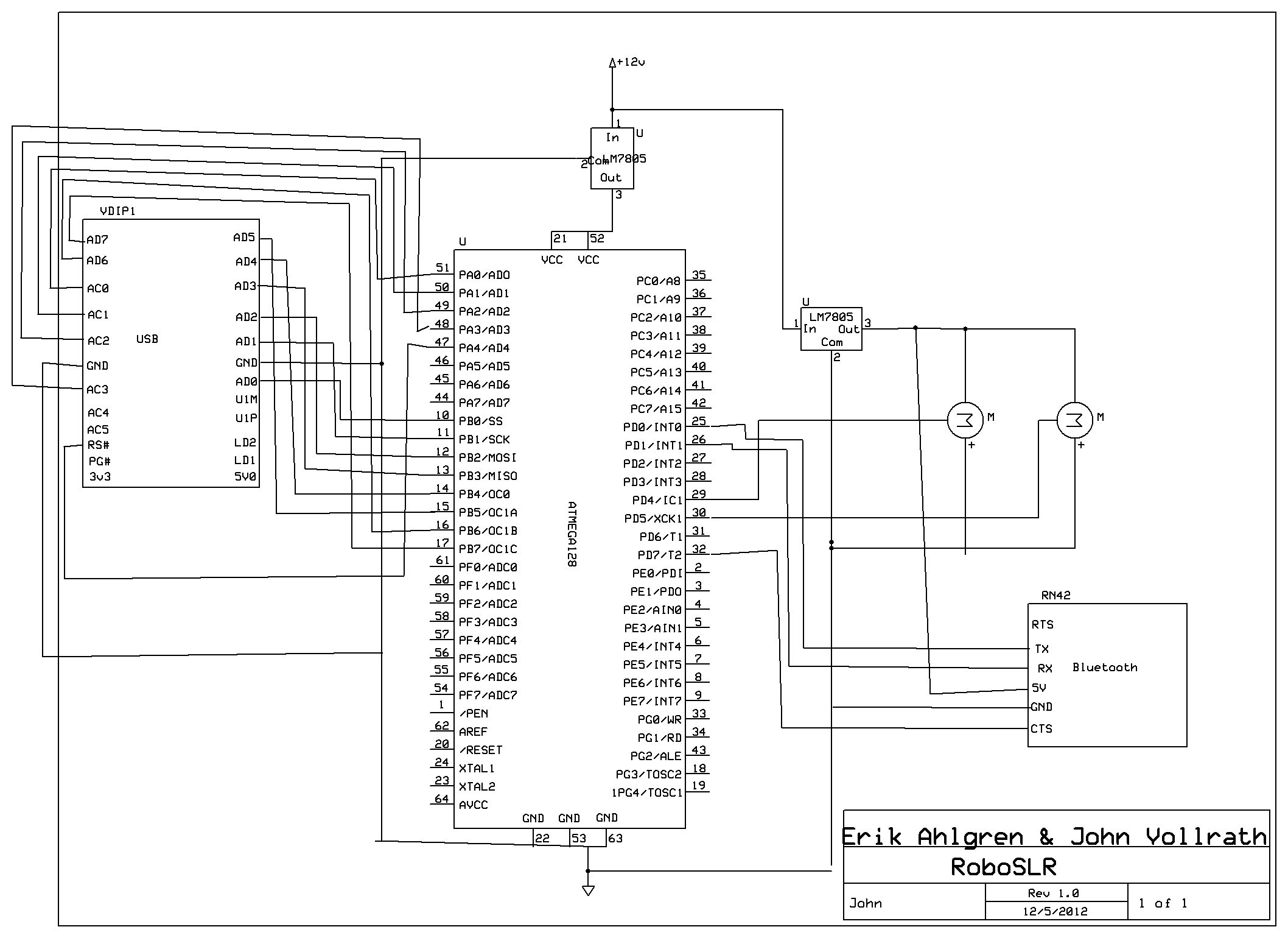
The idea behind Robo-SLR is to give freedom to the photographer to step away from their camera without sacrificing too much freedom to operate their camera. Therefore, the flow of our system is naturally user-driven. The flow starts when a user requests something of Robo-SLR. This request may be a PTP command to the camera, or a request to adjust the position of the camera with the servos. Either way, the command is sent through bluetooth on the user's PC to the BlueSMiRF module. The BlueSMiRF module then transmits the received data to the ATmega1284 via UART. Upon receiving a command, the ATmega decides whether it is a servo command or a PTP command. If it's a servo command, the ATmega adjusts the pulsewidth of the appropriate servo accordingly. Otherwise, the microcontroller figures out which PTP command to send, and sends it over a parallel connection to the FTDI USB host. The FTDI USB host then relays the PTP request to the camera, and returns the response and any data to the microcontroller. The microcontroller then relays the response and/or any data to the PC through the BlueSMiRF module if necessary.
System Diagram
The Robo-SLR system described above is illustrated below.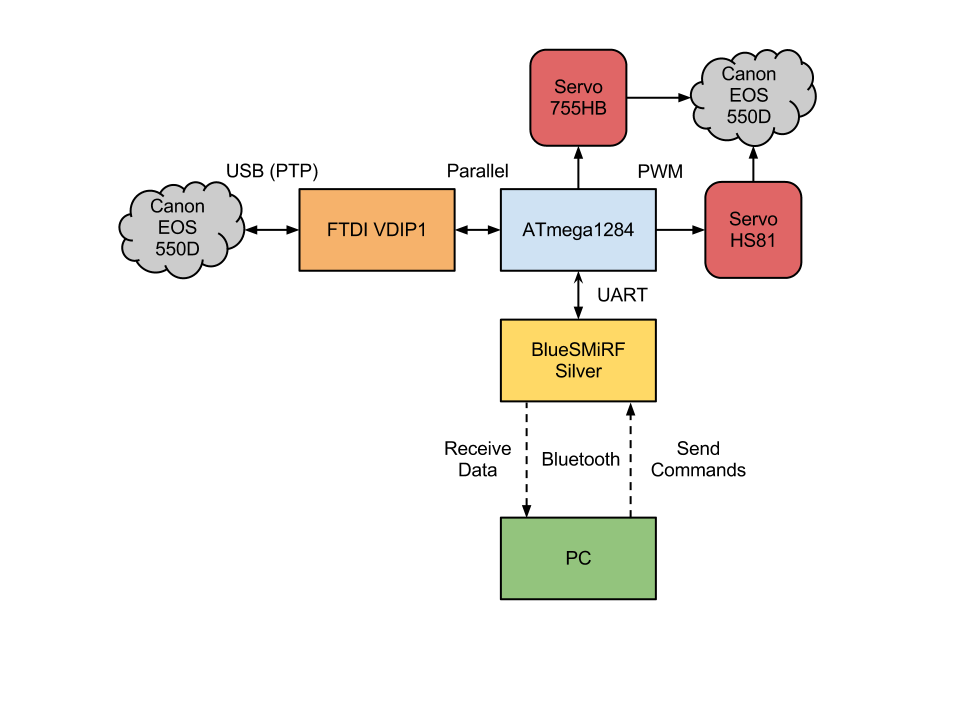
Everything we have done and more has already been achieved by commonly available PC software such as gphoto2. However, PC software does not allow as much freedom or flexibility as a microcontroller does out in the field. Therefore, we have
Standards
Robo-SLR uses the IEEE 802.15.1 standard for bluetooth communication.
The PTP protocol is used for communicating with the camera.
Software Design
Bluetooth
Our project used the BlueSMiRF Silver module to connect a user's PC to the ATmega1284 microcontroller. The UART feature of the microcontroller was used to handle sends and receives through the BlueSMiRF, and we were able to achieve up to 500kb/s baud rate. In order to provide hardware flow control, we used interrupts on the input buffer for the clear-to-send signal. When the input buffer is empty, clear-to-send is set low (it is active low). When the input buffer is full, clear-to-send is set high. Both of these occur through the use of interrupts. Also, we found the previous UART code to be a bit high in overhead, so instead we opted to create our own getchar and putchar functions.
Servo Control
We controlled two servos with timer1 on the ATmega1284 microcontroller through the use of pulsewidth modulation. The servos accept a 50Hz pulse, and center for each servo is 1.5ms, which corresponds to a counter value of 375 with a prescaler of 64. The range of both servos is 0.9ms to 2.1ms which corresponds to counter vlaues of 225 and 525 respectively. Every adjustment request only modifies the output compare register by 1, because the camera is heavy and it is desireable to make slow, steady adjustments.
Camera Control
Before the advent of the Picture Transfer Protocol (PTP), manufacturers implemented proprietary protocols to remotely control cameras. Since high-performance, cheap microprocessors have become popular, the demand for automated control has drastically increased. In order to make implementations more economical and scalable, the PTP was created.
The PTP defines a handful of constructs that the entire protocol relies upon. Foremost, a session is a logical connection between the Initiator and the Responder. Through this session, transactions are passed back and forth. A transaction can be one of four types: (1) a command packet, (2) a data packet, (3) a response packet, and (4) an event packet. The sequence of communication works like this: one of the devices issues an operation request to the other; depending on the operation code, the responder responds with a corresponding response packet. If the response requires more data than can fit in the response packet (more than 12 bytes), then a data packet is generated and sent before the response packet. The requester is responsible for knowing how to handle the response and data packets depending on what command it sent.
The command, data, and response phases are all synchronous - the PTP protocol does not allow simultaneous transactions. However, the Event packet is handled asynchronously from when it occurred. An example of when an Event type is used is when a Requester commands that a device take a photo; in order to know when the photo has been taken and stored, the responder will queue an Event when the photo is captured. The Requester then polls for the Event, and the responder is issued. One can see this is an intricate combination of synchronous processing within an asynchronous environment.
Perhaps the most challenging part of this project is knowing how to form the command, data, and response packets for the specific task you want to achieve. While the PTP defines a standard set of commands, responses, and properties that each manufacturer is responsible for implementing, the PTP can not possibly embody every feature that one manufacturer might want. As such, manufacturers create their own operations, data packets, and responses, which can do exciting things like take Live View Previews (the sought-after feature of our project). The problem with this solution is that there is almost no documentation available.
Without documentation to tell us how to construct the packets, we were forced to reverse engineer Canon's messages. Using a combination of tools, we issued commands to the camera and used USBlyzer to sniff the USB packets being sent back and forth. Through this, we successfully discovered the command codes needed to gather a Live View Preview from the Canon EOS 550D. However! There is more than just the opcode in a PTP packet - there are also attached parameters that are crucial to issuing the right command, and responding appropriately to data and response packets.
To show a concrete example of our challenge, study this photo:
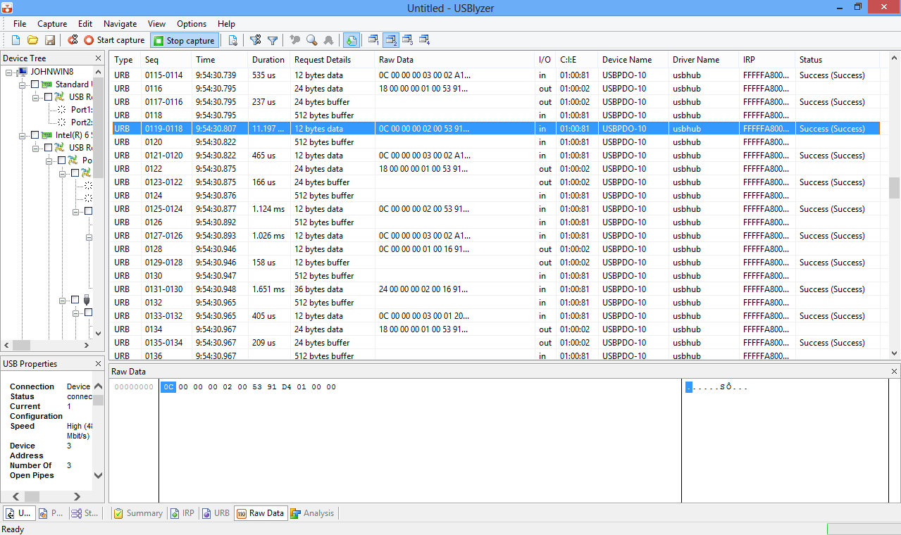
In this example, a program is trying to tell the Canon EOS 550D to gather a Live View Preview with the command packet (18 00 00 00 01 00 53 91...). However, the camera continuously responds with (0C 00 00 00 30 00 02 A1...), which means it's busy and not able to complete the request. When we originally ran the command packet on our microcontroller, we were confused because we knew we were using the correct command packet. As it turns out, the program must continuously request a Live View Preview, and eventually the camera will respond with a "Yes, here is your image!" type of message.
The final challenge to hurdle dealt with handling a large data packet on the AVR. Our plan was to read one byte from the FTDI controller, and then issue that byte to the Bluetooth radio. After the byte was out of the UART buffer, another byte could be read from the FTDI chip. This philosophy would have worked well, however, the control logic for determining when a data packet actually comes it tricky. There are false data packets, such as the one in the photo, where the camera returns a data packet, but it's merely a data packet saying "Hey, I'm not ready!" With the combination of a jubilee of other bugs, the Live View Preview feature was not able to be implemented. Our attempt at doing so can be found in PTP_basic.h:PTP_CANON_GetLiveView().
PC Software
In order to facilitate easy and intuitive management of the system, a PC program was written in python for the purpose of controlling Robo-SLR over the serial bluetooth connection. Using the pySerial library for python, a program was written to pass keyboard commands to the ATmega1284 through the BlueSMiRF module. The program first connects to the bluetooth module, and handles all serial setup configuration. Next, it loops infinitely on reading stdin, and passing the command along if necessary.
We borrowed vim's keyboard shortcuts of hjkl for manipulating the movement of the camera. h/l controls pan, and j/k controls tilt. m returns both motors to the middle position. hjkl are all incremental changes, but the upper case versions of these letters immediately move the servo into the corresponding extreme position.
In order to take a photo remotely, a PTP connection must first be established. In order to do this, the o command is used. After a connection is established, the p command may be used to capture a photo onto the camera.
Hardware Design
BlueSMiRF
We considered several options for integrating bluetooth into our system, and finally decided on the BlueSMiRF Silver module from Sparkfun. It's a board that uses the RN-42 bluetooth module from Roving Networks. Although bluetooth is a main component of our project, we wanted to spend most of our time focusing on the servo control and camera control aspects of our project. Therefore, the BlueSMiRF seemed like an obvious choice for a variety of reasons. The BlueSMiRF Silver fully implements the bluetooth stack, exposing a simple UART interface to communicate with. This meant that we were able to easily establish a serial connection over bluetooth from a PC to our microcontroller. The size of the BlueSMiRF meant that we could easily solder to it, where as the underlying RN-42 was much to small to solder to unassisted. Additionally, the BlueSMiRF handled the transition from our microcontroller's 5 volt signal to the 3.3 volt signal of the RN-42. Several similar full bluetooth stack boards were available, but the BlueSMiRF seemed more configurable and had Sparkfun's reputation behind it.
FTDI VDIP1
In order to act as a USB host controller, the AVR microcontroller needed a USB host module. Per the USB specification, there must be one USB host per connection; in this case, the AVR must act as a host to the DSLR. The FTDI VDIP1 packages a VNC1L microcontroller, which is capable of handling buffered serial, SPI, or parallel FIFO communication. For our purposes, we chose parallel FIFO. This allows higher bandwidth (8 bits per cycle, as opposed to 1 bit with serial), which is crucial for transferring images quickly. Along with these eight data lines, the AVR also interfaces with the FTDI through 5 control signals: RXF#, TXE#, RD#, WR, and RS#. These signals manage flow control; RXF# and TXE# are responsible for telling the AVR MCU whether the FTDI controller is currently receiving to transmitted, whereas the RD# and WR signals tell the FTDI controller that the AVR is busy.
However, in our implementation we found that the VNC1L performs inconsistently with parallel communication. It would work to some degree, but it was not at all reliable. Therefore we switched to serial instead, where we were able to get much more consistent performance.
Servos
Two servos are required for the mount system - a powerful tilt motor, and a less-powerful pan motor. For the strong motor, we chose a Hitec 755HB due to its low cost and adequately small size. This motor needed to be strong because significant amounts of torque are required to raise a 1.5 pound camera. Estimating a maximum torque arm of 6 inches, the motor needed at least 24oz * 6in of 144oz-in. The 755HB provides 150oz-in of torque at 4.8V.
The torque required to spin the assembly is far less than tilting it. The assembly will generally be within 3 inches of the axis of rotation, with the bulk of the weight in the center. As such, the Hitec HS81 was deemed strong enough (and it's very cheap).
Voltage Regulators
We used a 5V 3A voltage regulator to govern the voltage for the servos and the BlueSMiRF.
Mechanical Design
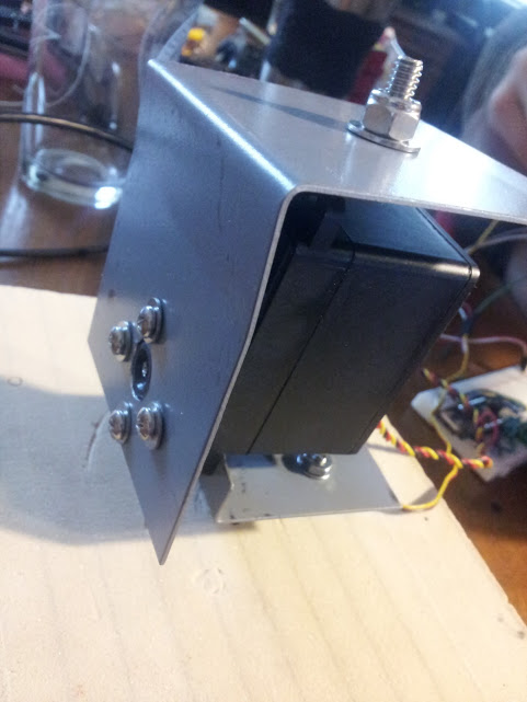
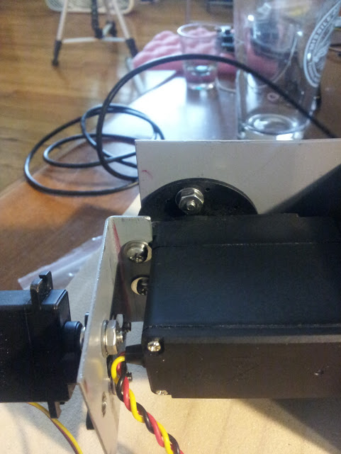
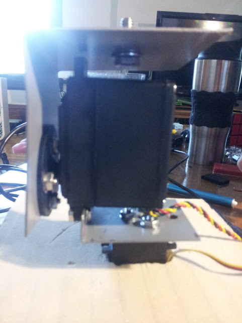
In order to create the tilt and pan functionality for the camera, we had to build a customized stand to accomodate the necessary servos and constrain the camera. The most torque-intensive movement is vertical tilt. Two servos were used to build the system: one for controlling pan and one for controlling tilt.
Two sheet metal plates and small bolts were used to connect the two motors together. One plate connected the tilt motor to the camera, and the other plate connected the pan motor to the tilt motor. For demonstration purposes the pan motor was secured to a block of foam we had laying around to prevent the system from tipping over. Alternatively, it may be bolted down to a solid base. Holes were drilled in the arms of the servos in order to allow the arms to be bolted to the plates. The servos already have mounting holes built in, which we used to secure the two servos together.
The plate connecting the camera to the tilt servo was made out of a 6" x 3" piece of sheet metal which was bent at 90 degrees. One face had holes drilled in it to accommodate the servo arm, and the other had one hole in order to accommodate the camera mount. A 1/4 x 3/4 bolt was secured through the camera mount hole with a few washers and a nylock nut to ensure it stayed in place. The camera then screws onto the bolt, similarly to how it would function on a tripod. 6-32 x 3/8 bolts were used to secure the plate to the servo arm along with washers and corresponding nuts.
The plate connecting the pan arm to the tilt servo was made out of a 2" x 3" piece of sheet metal, which had a lip bent at 90 degrees in order to accommodate the servo mounting holes. Holes were drilled in both faces to accommodate the pan servo arm and the tilt servo mounting holes. Bolts were secured through these holes to assemble the system.
The most strenuous component of moving the camera is the tilt system. Our torque arm was approximately 3" long, and our camera weighs about 2 lbs. Our tilt servo is rated for 153oz-in of torque. At rest with our torque arm, the camera will torque 32 * 3 = 96oz-in, and the tilt servo is rated for 153 oz-in at 4.8 volts. We believed this to be a safe margin, and it proved to work fine.
The pan servo is only rated for 36 oz-in, but because it does not see much torque directly this did not end up being a problem at all.
The photos below illustrate the assembled mount system.
Results
Reliability Issues
Throughout the process of development, the BlueSMiRF and/or UART on the ATmega1284 proved to be somewhat unreliable. We ended up writing our own UART code to smooth things out by decreasing complexity, but that didn't end up working out as we were unable to track down our most serious error.
Safety
Hard limits on servo parameters ensured safe operation. Additionally, our code was tuned to make slow adjustments even though the servos are capable of changing angles very rapidly. Cameras are expensive, and it's in everyones best interest to keep them safe!
Usability
The entire point of Robo-SLR is to improve usability of existing camera devices. People who have disabilities relating to their ability to move will appreciate being able to move and control cameras remotely.
Failures
The most disappointing failure was the unreliability of our communication with the camera. Frequently, attempts to open a PTP session with the camera would fail, leading to wasted time and many power cycles of both the AVR and the camera. In addition to that, the servos have developed a mysterious character, in that they like to do whatever they want (sometimes). In order to make this device marketable, a more refined PTP implementation has to be developed; one that is resistent to errors and can recover an erring device so the user does not have to manually cycle power or unplug the device.
Conclusions
Specifications
We managed to implement the desired features for Robo-SLR, but they do not work together for some reason. We spent many hours debugging but were unable to determine why the two pieces of code simply refused to work in each other's presence.
Improvements
Given more time, we would have completed the reverse-engineering process of the data packets, and would have been able to remotely view photos taken on the camera. We were very excited to have this as part of our project, but unforseen issues with wireless communication hindered our ability to make as much progress as we would have liked. Additionally, the mechanical design could be improved for additional rigidity, and a stronger servo for panning would be preferable.
IP Issues
We re-used some code from Luke Skaff who implemented some basic PTP functionality on another AVR device. However, our code does much more than his does. We attempted to reverse engineer the result of the viewfinder capture request, but we were unsucessful in doing so given our time constraint. Therefore, we don't have anything to worry about. There is already open source software that does what we're trying to accomplish, so there's little opportunity for a patent. However, that project doesn't run on a microcontroller!
Ethical Considerations
As tough as it is to admit it, our system doesn't work the way we intended despite our best efforts. We have two independently working pieces of our code: taking a snapshot with the camera, and controlling the motors. This admission shows that we're being honest and true to the data about our system in action. Our goal was to improve our understanding of how the undocumented parts of the PTP protocol work, and show off some of the special features discovered. Even though we don't have the system working completely at the time the lab was finished, both of us wish to see the project through and open source it to everyone's benefit. It was incredibly irritating for us to attempt and reverse-engineer and otherwise progress in our project where companies and individuals had made a concious effort in the past to conceal their code and intents. Even a little bit of documentation goes a long ways, and there's no sense in having everyone re-invent the wheel all the time. However, we do fully acknowledge the value of the work of those who came before us. Luke Skaff's base code for PTP served as a useful guideline for us, although we wanted to take it far beyond what he has done.
Legal Considerations
Since Robo-SLR uses bluetooth, it is bound by FCC laws. It must not transmit any harmful interference, and must accept any harmful interference given. Our bluetooth stack was entirely managed by the BlueSMiRF, so this wasn't much of a concern for us.
Work Distribution
Much of the work of the project was performed collaboratively, especially for debugging and tackling tough design challenges. However, we each had a few areas we were primarily responsible for.
Erik
Erik was primarily responsible for writing the PC software, UART communication code, and interfacing with the bluetooth module. Erik also took care of the markup for the website.
John
John was primarily responsible for manufacturing the mechanical pieces of the project, implementing the PTP protocol, and communicating with the camera over USB through the FTDI chip.
Appendix A: Code Listing
See zip file below
roboslr.zip
Appendix B: Schematics
Appendix C: Cost Details and Parts List
Part |
Qty |
Cost |
Notes |
BlueSMiRF Silver |
1 |
$39.95 |
Bluetooth Module. Purchased from Sparkfun |
755HB |
1 |
$27.99 |
Hitec Servo Motor. Purchased from Amazon |
HS81 |
1 |
$13.67 |
Hitec Servo Motor. Purchased from Amazon |
FTDI VDIP1 |
1 |
$5.00 |
USB host module. Borrowed from the lab |
ATmega1284 |
1 |
$5.00 |
ATmega1284 and board from the lab |
Assorted Washers |
20 |
$0.50 |
16 small washers and 2 larger washers. Purchased from Lowe's (part numbers 409485, 63306) |
6-32 hex nuts |
8 |
$0.50 |
Nuts for the servo arm bolts. Purchased from Lowe's (part number 409466) |
6-32 x 3/8 bolts |
8 |
$0.50 |
Bolts for the servo arm mounts. Purchased from Lowe's (part number 409487) |
1/4 hex lock nut |
1 |
$0.10 |
Nut for camera mount bolt. Purchased from Lowe's (part number 63403) |
1/4 x 3/4 hex bolt |
1 |
$0.10 |
Bolt for the camera mount. Purchased from Lowe's (part number 55817) |
Canon EOS 550D |
1 |
N/A |
John's camera. Owned for more than a year. |
Bread board |
1 |
N/A |
John's breadboard. Owned for more than a year (previous projects) |
12V Power Supply |
1 |
N/A |
John's old power supply from external hard drive. Owned for more than a year |
Laptop |
1 |
N/A |
Erik's laptop. Owned for more than a year |
Voltage Regulator |
1 |
N/A |
5v regulator. John has owned it for more than a year (old FSAE supply). |
Scrap Sheet Metal |
N/A |
One 6" x 3" piece and one 3" x 2" piece. Scavenged from the ELL |
Total Cost: $93.31
References
ATmega 1284 Microcontroller
Bluetooth
RN-42 Datasheet (used by BlueSMiRF Silver)
RN-42 User Manual
BlueSMiRF Schematic
BlueSMiRF Wiring
Sparkfun: BlueSMiRF Silver Product Page
Servo
PTP
PTP Protocol (full protocol specification)
Using PTP Protocol (high level description)
Arduino PTP Implementation
PTP over USB
Using PTP with EOS
USB
VDIP1 Datasheet
FTDI Communication Information
Serial
pySerial (used for serial over bluetooth)