"A wireless system to control the lights, fans and other home devices by human's voice."
Project Soundbyte
Motivation top
We design a smart home control system which allow people control their home devices by voice command at home. This is a wireless, voice control system. People could control almost all the facilities at home including lights, fans or even back ground music. Right now, the basic function of lights control, fan control and music control have all been implemented. Except for basic turning on and off of fasilities at home, we also realize the function of fixed-time control, and error detection when some device is broken. The system is quick enough for respond all the commands.
Our smart home system is a simulation product for the future life. The purpose of it is to make people's lives more convenient. To replace turn on or turn off on switches by hand for current product, our system is controlled by voice. That should be a trend for the future 10 years which we believe that it is coming to real product soon. How to make people’s life more convenient, more comfortable, more safe and how to save more energy will be the series of questions we will care, discuss and design in our project. Just imagining, after you cook a big pot soup and want to leave the kitchen, you don’t have more hands to turn off the kitchen’s light. If our project becomes a mature product, you can set up our system in the home, you can turn off the lights by voice when you hold a pot soup at the same time. When you read the book in bed at night, you are not sure when you will sleep, you can tell the system when you want the light turn off, the timer in the system will help count the time and turn off the lights with the time you have set.
Early Work top
Why we choose wireless signal transmission?
When someone gets home and wants to enable light, fan, music at home, he may use his voice to control his household appliance. However, the transmission distance of the voice is short and it is even hard to recognize what you said when there is some noise mixed with the signal. Sometimes the voice recognition chip will send out wrong instructions because of the noise outside. So we decide to place a central control unit in the center of the room and send digital signal wirelessly to where other microcontroller is. Once the receiver gets the signal, it will operate on/off/dimmer function which has been programmed in it previously. As xbee could transmit at most 1000 meters, this method avoids the distance problem and signal interference problem.
Why we choose xbee?
XBEE promises many advantages over existing remote control solutions, including richer communication and increased reliability, enhanced features and flexibility, interoperability, and no line-of-sight barrier. In our project we use XBEE for point to point communication. It is efficient and enough to be used in household. The transmission of signal won’t be blocked in a long distance and even by a wall. Due to this spec of the xbees, we may put the center voice recognition microcontroller in the center of one household so that it could communicate any other microcontroller (which has xbee receiver with it) and enable different functions by sending out different instructions. Here, I use different characters, like “a”,”b”,”c” etc to represent controls on fan, lounge room LED and bedroom LED.
X-CTU is the program provided by digi to initialize and test with xbee communications. We change the baud rate to 9600, set the same pin number for two xbees through the program so that it is ensures there will be no other xbee or RF devices interfering the wireless communication between two our two xbees.
High Level Design top
Rationale and Sources
Many companies on the school career fair showed their products for students. Lutron, a famous lighting control company, focus on the light system for house, company and some other building. They showed us their high-level LED products, with the basic entire control system costs around $3000. We got interested in their product and also figuring out a more convinient way to control and save energy.
After discussing, we consider it could better if we implement the wireless, voice control system in the household. The basic idea of our project is when people stay in the room and within a distance of the device they wants to control, they could control the house electrical devices by voice instructions. Under most of the circumstances, this system will bring more convenience in people’s lives.
Logical Structure
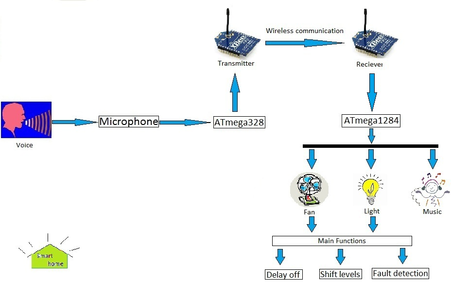
Figure 1:Overview of Logical Strcture Diagram
There are two CPU in our project, ATmega328 and ATmega1284. We set up the wireless communication by two Xbee chips. One of them connects with ATmega328 working as the transmitter to transmit the signal, another one is connected with ATmega1284 to be the receiver. We pick up ATmega328 to be our transmitter part because there is a microphone on it which could receive and store the voice signal from people. When people say the voice instruction, microphone gets it first and then ATmega328 receive it. By the program controlling, ATmega328 will send the signal to transmitter Xbee. When the Xbee is enabled, it will send the corresponding signal to the receiver Xbee by the different voice instructions. When the wireless communication set up successfully, it will send instructions for ATmega1284.
We set up two timers, timer0 and timer2 for four PWM waves to do the function of turn on, turn off and shift the level of lights and fan. On the other hand, there is one pin which is used to turn on and turn off the music player by the high voltage or low voltage enabling the MOS transister. One more function is delay off realized by timer1. User could tell the device when to turn off the lights or fan automatic. There still is a time counter to show the time decreasing process. In order to tell the user when the light or fan are broken, the LCD could show the detail to remind user the light or fan broken by open circuit which is the fault detection function. Generally, our project could control the lights, fan and music player parallel.
Trade-offs
We decided the idea of voice control smart home system at the beginning of this project. Because we owned the ATmega328, so we were looking for some voice recognition module to put on it. At final, we chose the EasyVR Shield - Voice Recognition Shield which is perfect to suit for ATmega328 and has the high level voice recognition function. It is the cheaper one which is under the budget, but still cost us around $50. The little more cost increase the final budget for our project. In order to make a tidy and beautiful circuit, we used much time to design the circuit to improve space utilization. We set up ATmega1284, one Xbee chip, one LCD, one music player chip and three PWM wave circuits on three solder boards (6 inch). We got a good wire connection on the solder boards and carefully to solder and re-solder them together. Our initial idea was to use batteries to provide the power for the whole circuit. By this way, we could take our device convenient. But after test, we found the batteries is really hard continuously provide the power for three different home devices and sometime the voltage is instability. Finally we had to give up it and changed to use the power supply in the lab.
FCC Rules
We used the xbee chips to set up the wireless communication. To make sure if we could use the xbee to set up the wireless communication in the United States, we need to check the Federal Communications Commission Rules. The Xbee chips are operated in the ISM 2.4 Ghz frequency. After we check the FCC rules part 15 subpart B, we got 2.4 Ghz frequency are exempt from complying with the technical provisions of this part which prevent the harmful interference in a residential installation.
Existing Patents and Copyrights
To make sure we don’t infringe someone’s patents or copyrights, we search the key word in google after we are done. We try to search the “voice control home” and other similar key word, we find a product named HAL, the Home Automated Living at smarthome.com.(HVL,Home Automated living) We never read their product detail or their website before. After we finish our project, we read their product and compared it with our project. We find they are not same. HVL connect the cellphone with the software in PC by the telephone wire. When people want to control their home device they need make a phone call for the device and send the commands which they want to control, such as when to turn on the living room light and turn on how long. All of them are controlled by the computer. But our device is totally different. People need to stay in the home and have a short distance with the microphone. Use the voice instructions to control the home device which they want to.
Hardware Design top
Hardware Overview
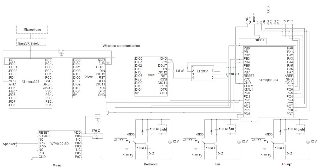
Figure 2:Overview of Hardware Design

Figure 3:Overview of Physical Map
These are the overview of our project schematics and physical map. We solder all of them in three solder boards. The microphone, EasyVR Shield and transmitter Xbee are connected on the ATmega328 chip and no need to solder. ATmega1284 connect to LCD and provide the voltage to the receiver Xbee. We pass the Vcc in a voltage regulator to get the 3.3V to the Xbee. On the other hand, there are three pins provide the PWM waves to the three different home devices. There is one pin is used to connect the gate of NMOS which is let the VCC flow in to the NMOS and into the voltage regulator to get the 3.3V output to the music player chip.
Part1-Transmitter part
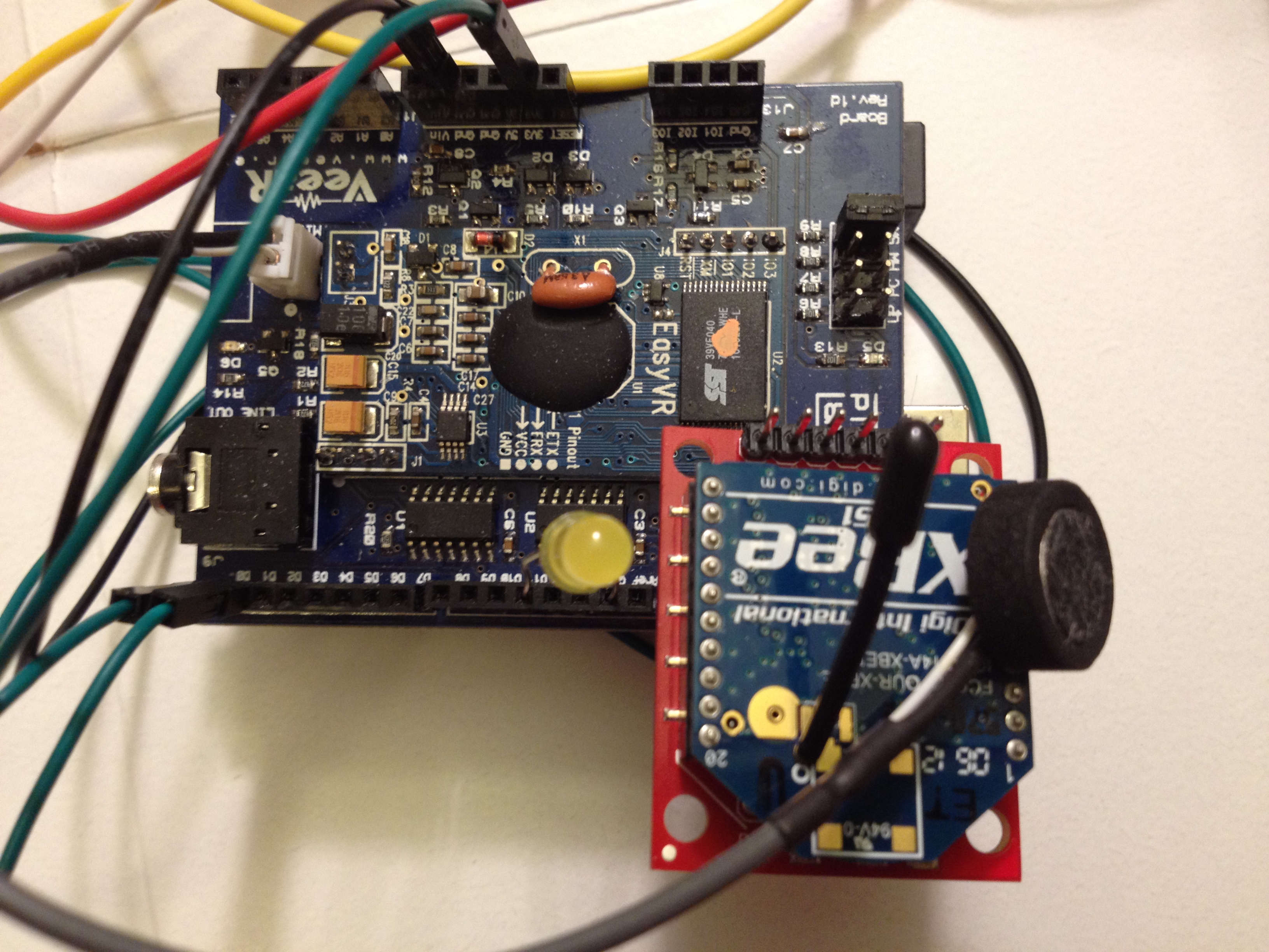
Figure 4:Transmitter Part
In this part, there are three part, EasyVR Shield which has the microphone, the ATmega328 and the transmitted Xbee. With the ready-made board we can put the EasyVR chip on the ATmega328 direct. We input the 3.3V from the ATmega328 to Xbee and connected the Xbee and ATmega328’s ground. In order to transmit the signal from Xbee we connected Xbee DOUT pin to ATmega328 (PCINT16/RXD) PD0 pin.
Part2-Receiver Part
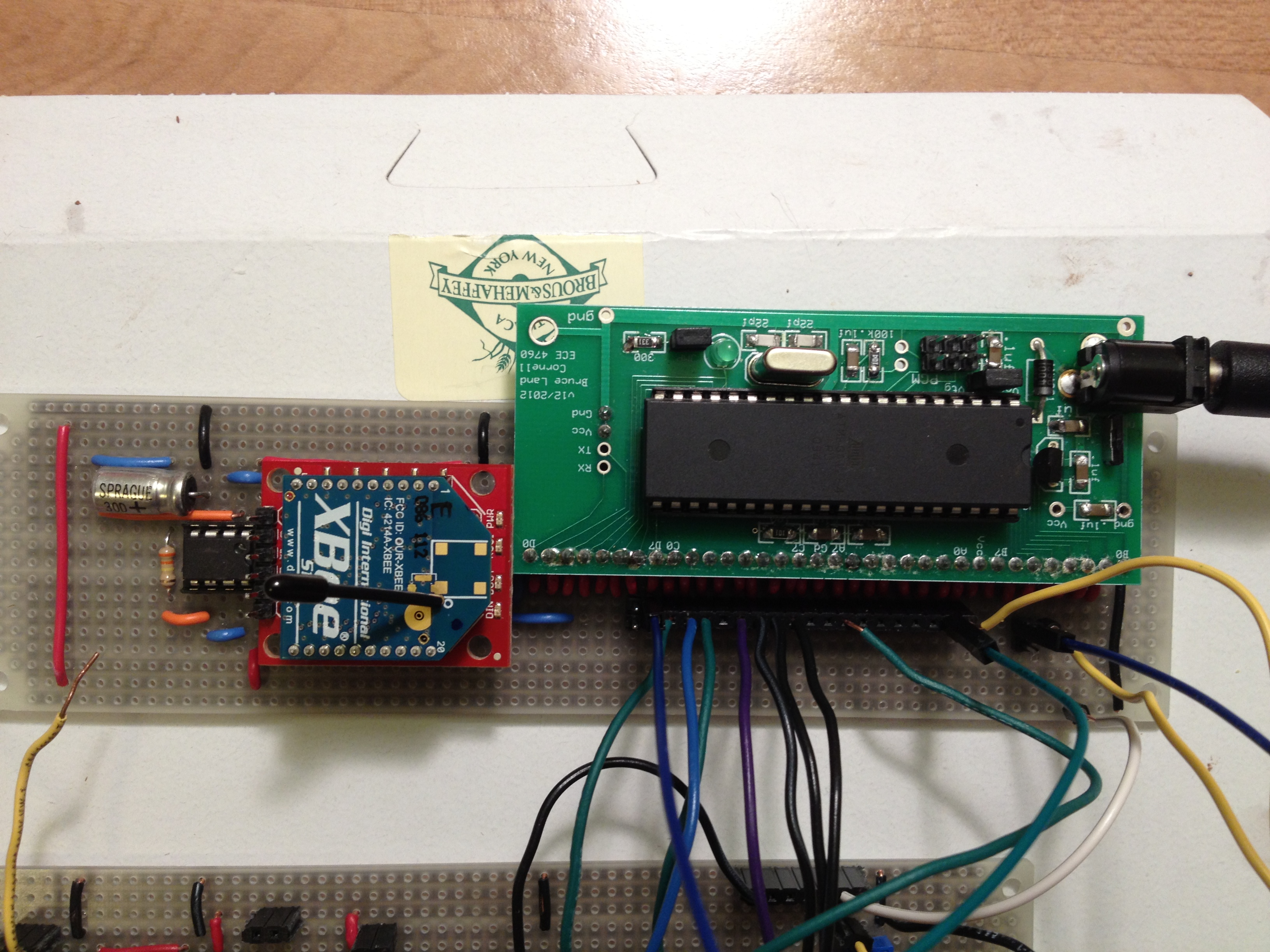
Figure 5:Receiver Part
We soldered the MCU board by ourselves and we followed the lab1’s lecture to initial the CPU. And then we used it to provide 5V output for all the other chips and connect it with the LCD which follows the lab1 lecture. After check the data sheet of Xbee we connect the DIN with ATmega1284’s PD2. There is a little different between ATmega328 and ATmega1284 at the power output. There is no 3.3V voltage output at ATmega1284. So we use the voltage regulator LP2951 to drop the 5V output to 3.3V. Set up the circuit of LP2951 with the datasheet, we could get the stable 3.3VV output.
Part3-LCD and Music Player
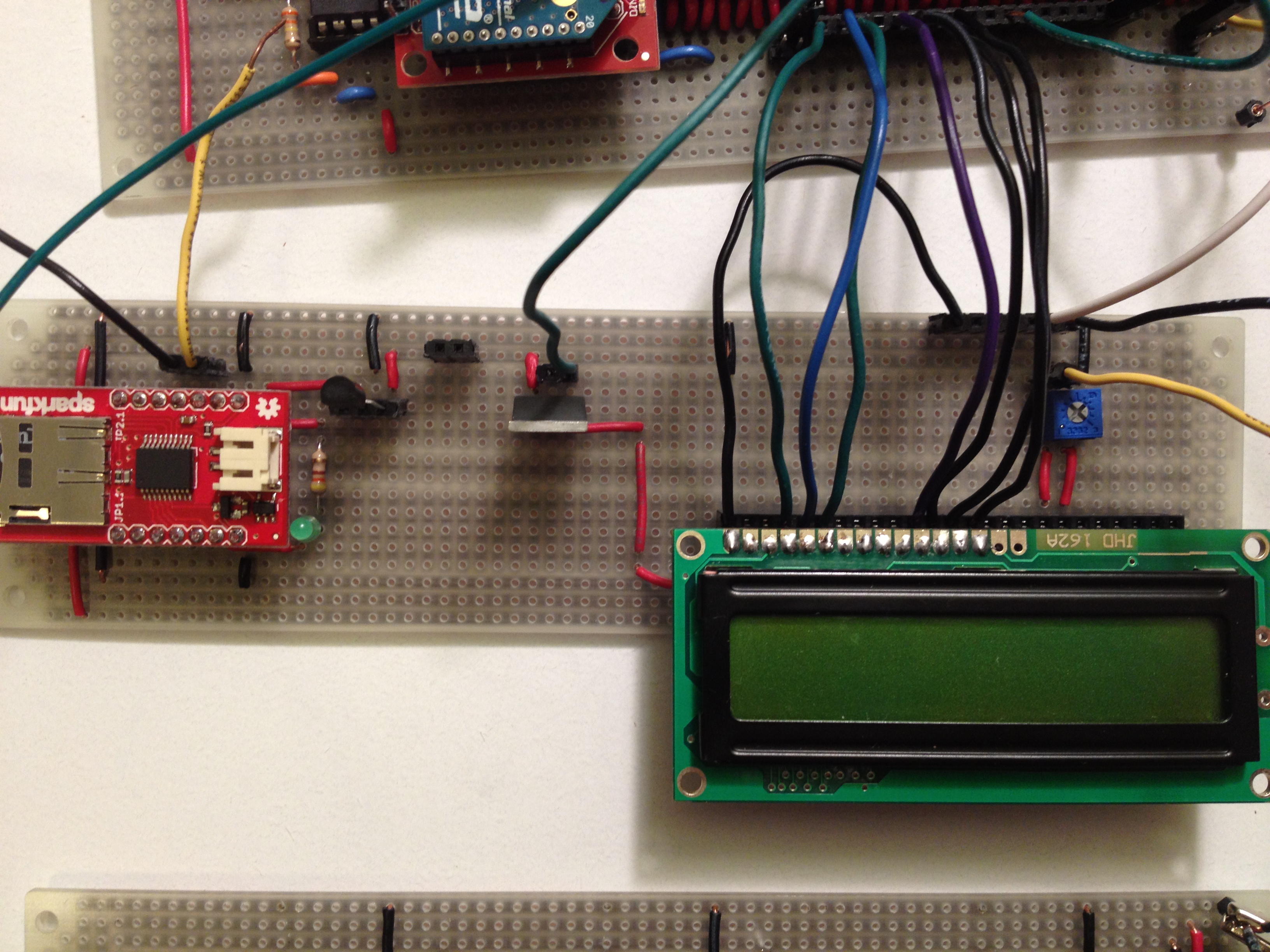
Figure 6:LCD and Music Player
For this board, we set up the circuits of LCD and the music player chip. The music chip is named WTV020-SD module. There are different modes in this module. The MP3 mode, Key mode, Key mode, Loop play mode and two line serial mode. Because we only play the background music, so there is only one music in it. We pick up the loop play mode to play the music. Here is the detailed schematics of WTV020-SD which come from the datasheet.

Figure 7:LCD and Music Player
When we try to use one ATmega1284 pin to enable the chip and provide 5V input into the voltage regulator. But there is a problem here, the current is very low and we can’t let the music player chip work. So we put a NMOS here and let the pin voltage to connect the gate and let the VCC to be the power supply to pass into the voltage regulator to get the 3.3V output. In the way, we could use the program the control the only one pin voltage to get the music player work.
Part4-PWM Circuits
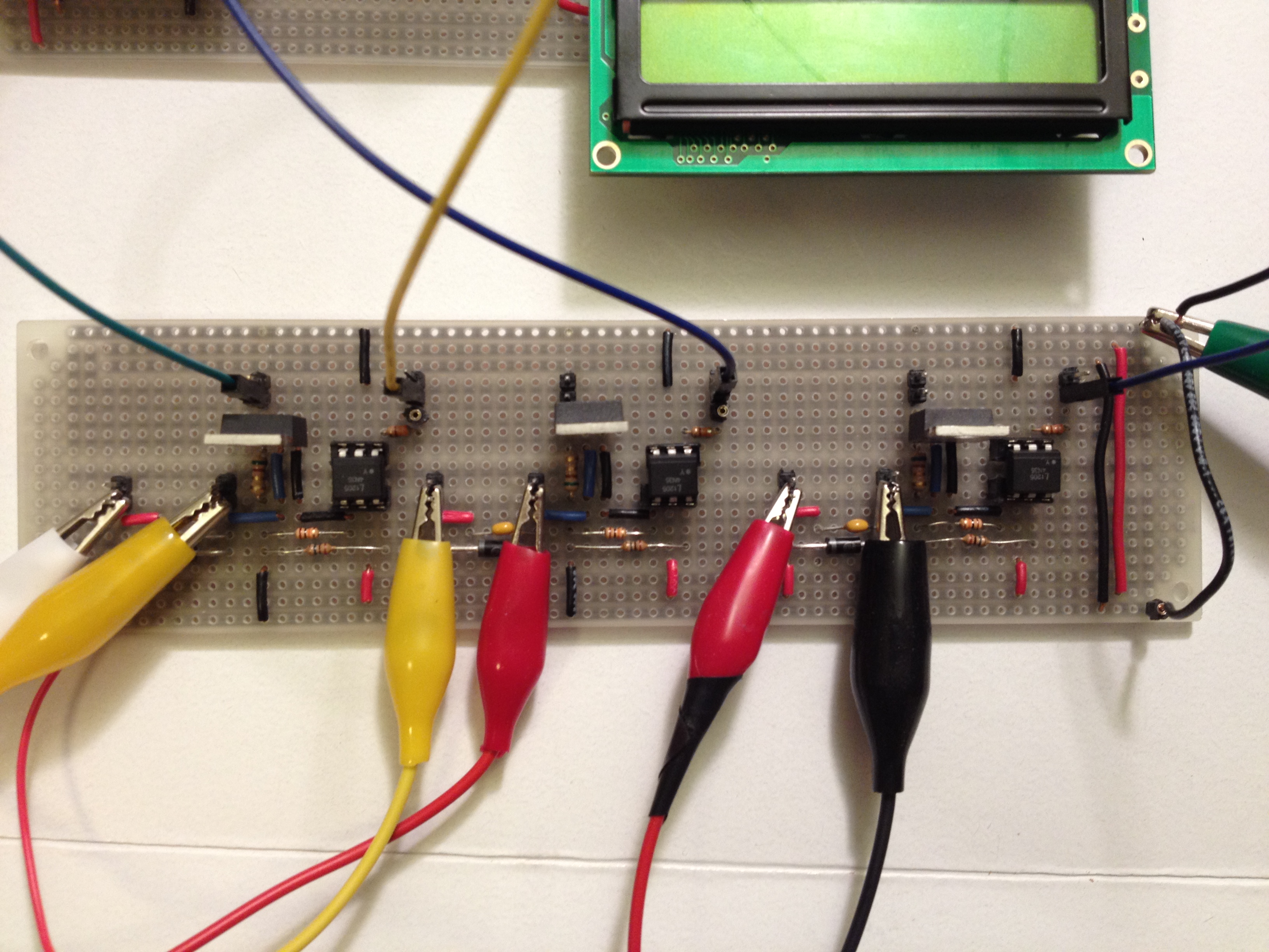
Figure 8:PWM Circuits

Figure 9:PWM Circuits
We set up three same PWM circuit to control the home device here is the schematics of it. For here 4N35 is used to separate the light with microcontroller. Because there would be current flow back from motor and will harm the I/O pin of microcontroller. The BUZ73 is an N-MOS transistor, it works as a switch. When VGS>2V(which is logic high), DS of the N-MOS link together and work as a shortcut. The motor works under 12V; When VGS<2V(which is logic low), DS of the N-MOS break and the motor stop working.
The diode is used to absorb the energy stored in the motor, actually when the motor’s supply voltage is suddenly reduced, there will be a risk that the voltage will go back and may harm the MCU, so the diode can eliminate the risk. At the low voltage of the PWM cycle, motor is turned on and the diode is reverse biased, the inductive current flow is downward when PWM is changing from high level to low level and the inductive current flow is upward when PWM is from low level to high level. The capacitor is used to remove the high frequency.
At the source of BUZ73, we add a resistor to do the function of fault detection. We use ATmega1284 to test the voltage between source and ground to check if the device works in a right way. If not, the LCD will show the device are broken, maybe some reason it short.
Software Design top
EasyVR Voice Recognition(on Atmega328)
EasyVR Commander could record the voice someone speak in the chip and then compare the voice said by people when they send out instructions. The hard part of voice recording and recognition is that we need to choose different pronounce to record in the chip, the more difference each instruction has, the better. After we choose and record and training with the most recognizable signals, we may use compiler to write programs in atmega 328. Here we use arduino instead of directly programming 328 using AVR studio 4 as the EasyVR.h library is written in C++ and we can hardly use avr studio to program with it. Therefore, we may use the function and method in the library to get instruction from what someone said to the chip meanwhile send out the character in the form of “a”,”b”,”c” etc. After choosing the baud rate of transmission of 9600, the pair of xbee could cooperate correctively and efficiently.
Dimmer by Pulse-width Modulation(On Atmega 1284)
Pulse-width modulation (PWM) is a commonly used technique for controlling power to inertial electrical devices, made practical by modern electronic power switches. Why we choose PWM to control the household appliance here? As we heard of dimmer, it is actually realized by changing the average voltage on an electric appliance in an energy- saving way. In this project, we choose to generate PWM from four of the PWM pins which could be enabled in ATmega 1284 to create dimmer, especially on LED control. PS: Because the rated voltage on the LED bulb is 12v, so we can’t use a lower voltage to make a “dimmer”.
Use of Timer0, Timer1 and Timer2(On Atmega 1284)
According to the datasheet of Atmega 1284, we know that 1284 has six PWM channels. In this project, we need to use at least three of them. One PWM is generated for controlling bedroom LED bulb; one PWM is generated for lounge room LED bulb and one is for controlling a fan in the room. We set up timer 0 so that we can enable PB3 and PB4 as two PWM output pin. By changing the value of OCR0A and OCR0B, we can easily determine what average output voltage added on the LED bulb. We do the same thing on timer2 and enable PD6 and PD7 which could also modify its value by changing OCR2A and OCR2B. Timer1 here is used for creating a counter which is used to realize the function of fixed time control. When someone needs some of the facility in the home turned on for several, he could set the time and just leave.
Error Detection use ADC Converter (On Atmega 1284)
For implementing the function of error detector, we designed a circuit based on the PWM control circuit. We add a small resistor which equals w5 ohms and connect with LED bulb or fan in series in order to get the voltage on the resistor and see whether the circuit is an open circuit. As when the LED bulb or the fan is broken, there won’t be any voltage on the resistor, so if we could read the voltage value in analog, we could realize the error detector function. The way to use the ADC converter is by setting up the left adjust and turning on the internal reference, then we could turn it on and use the defined pin to get the value from ADCH. By doing a bit algorithm for convert the counts to analog value, we may get the exact value of the voltage on the resistor.
Wireless Receiving (On Atmega 1284)
Wireless receiving side on Atmega 1284 should take care of the CPU frequency, baud rate and external interrupt service routine (USART1_RX_vect), we set the baud rate as 9600 and use these two equations [(F_CPU/16/(BAUDRATE+1))%256 and (F_CPU/16/(BAUDRATE+1))/256 ] to set high byte and low byte of UBRR1. After initializing the data frame format as asynchronous mode, no parity, 1 stop bit and 8 bit size, we could get the data received wirelessly from data from the xbee on Atmega 328.
User Commands
Basic function and instruction said by user
| Number | Function | Commands |
|---|---|---|
| 1 | G1_BEDROOM_ON | turn on bedroom----------'a' |
| 2 | G1_BEDROOM_OFF | light off---------------------'b' |
| 3 | G1_BEDROOM_DIMMER | bedroom dimmer----------'c' |
| 4 | G2_FAN_ON | turn on fan-----------------'f' |
| 5 | G2_FAN_OFF | shut fan--------------------'g' |
| 6 | G2_FAN_LOWER | fan lower-------------------'j' |
| 7 | G3_LOUNGE_ON | lounge on------------------'d' |
| 8 | G3_LOUNGE_OFF | turn off lounge------------'e' |
| 9 | G4_MUSIC | music----------------------'h' |
| 10 | G5_30SEC | Bedroom on for 30 sec---'i' |
Table 1:Basic Commands
Results top
For the result, we are able to control all the devices we have inplemented in the circuits by eleven different commands which will also be shown on the LCD at the same time. We will demonstrate more details of voice control in the video.
Initialization Mode
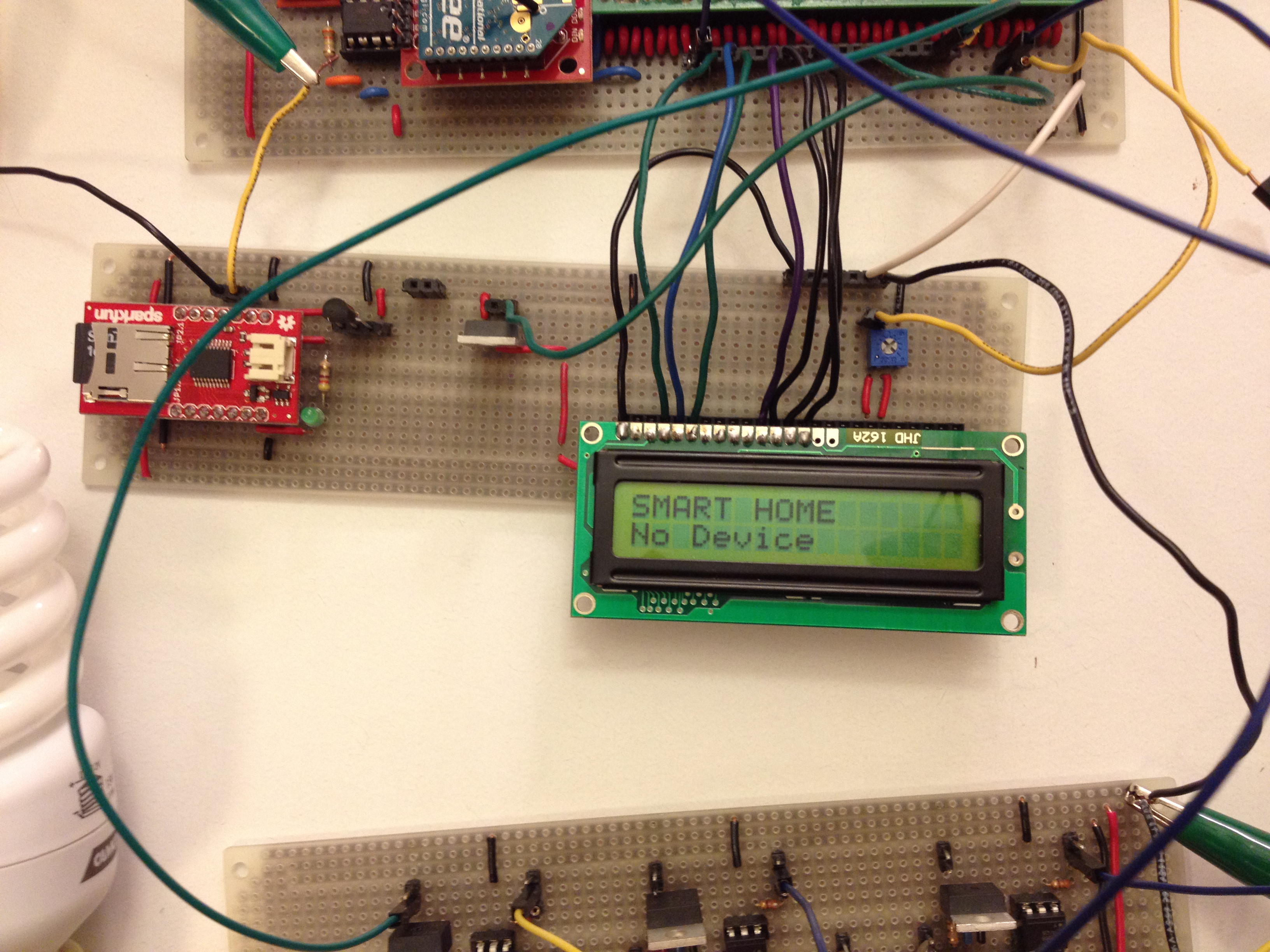
Figure 10:Initialization Mode
Once we power on the Atmega 1284, we are able to see the initialization showed on the LCD screen with the lable "Smart Home" and "No device" which means the LED in the bedroom is not on. Here, we get a feedback detection to test whether one appliance in home is in good condition or not. In this project it is the LED bulb in the bedroom. So once the power is on and the LCD still shows "no device" as the circuit is open, it will notify the user that something is wrong with the LED bulb.
Fan On Mode
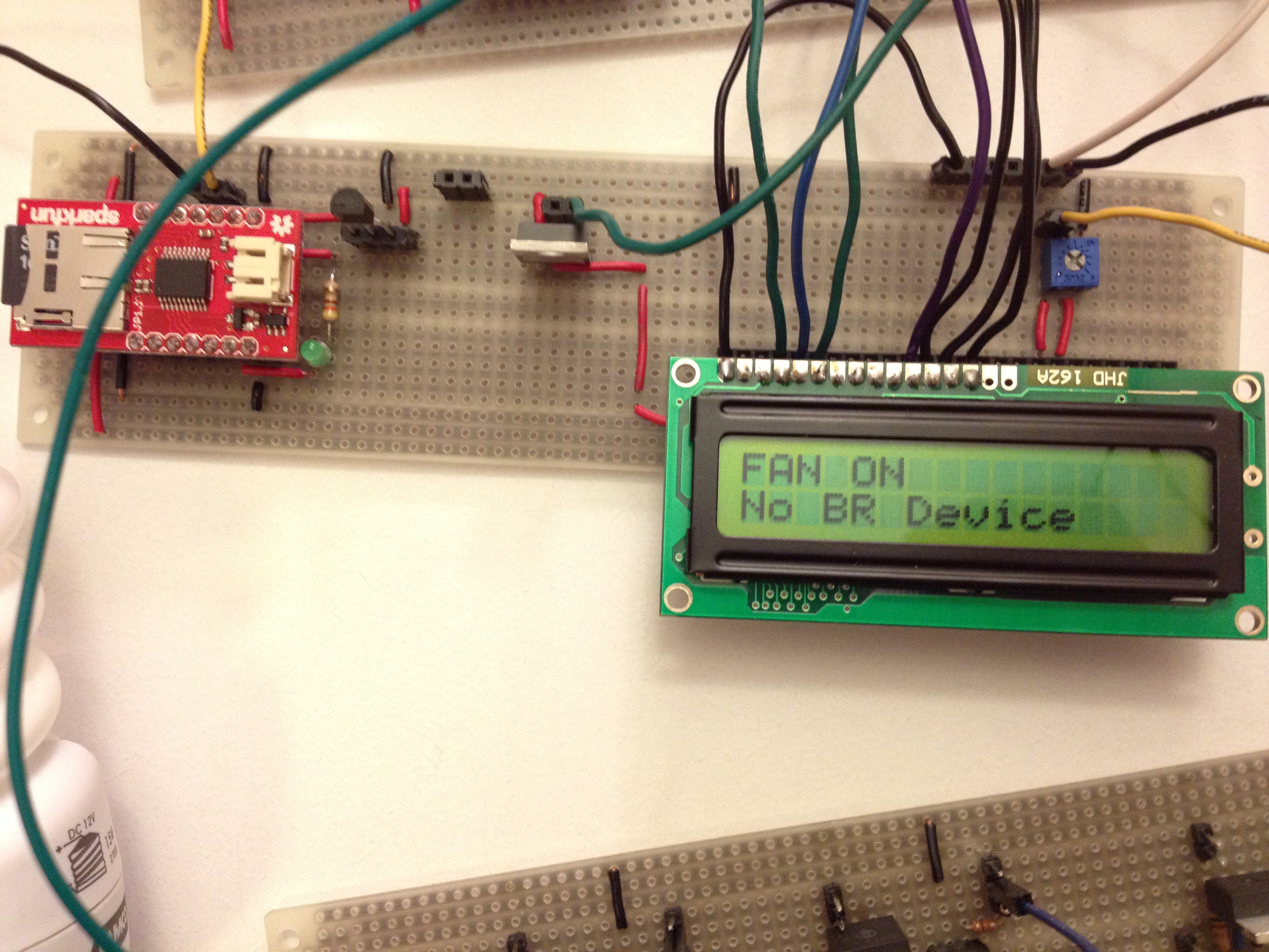
Figure 11:Fan On Mode
This mode is actived by receving the command of "turn on fan". Once our voice of "turn on fan" is recognized by the voice recognition chip, the command will send out with a character of "f" through the Xbee from the Atmega 328 and received by Atmega 1284. Once the interrupt service routine is on, the character will be stored in UDR. Atmega 1284 will address what the command is and operate on family appliance. Here, the character is "f", OCR2A will turned to 0 so that fan will run at full speed. Meanwhile "FAN ON" mode will be shown on the LCD screen.
Fan Lower Mode

Figure 12:Fan Lower Mode
This mode is actived by receving the command of "fan lower". Once our voice of "fan lower" is recognized by the voice recognition chip, the command will send out with a character of "j" through the Xbee from the Atmega 328 and received by Atmega 1284. Once the interrupt service routine is on, the character will be stored in UDR. Atmega 1284 will address what the command is and operate on family appliance. Here, the character is "j", OCR2A will turned to 100 so that fan will slow its RPM. Meanwhile "FAN LOWER" mode will be shown on the LCD screen.
Fan Off Mode
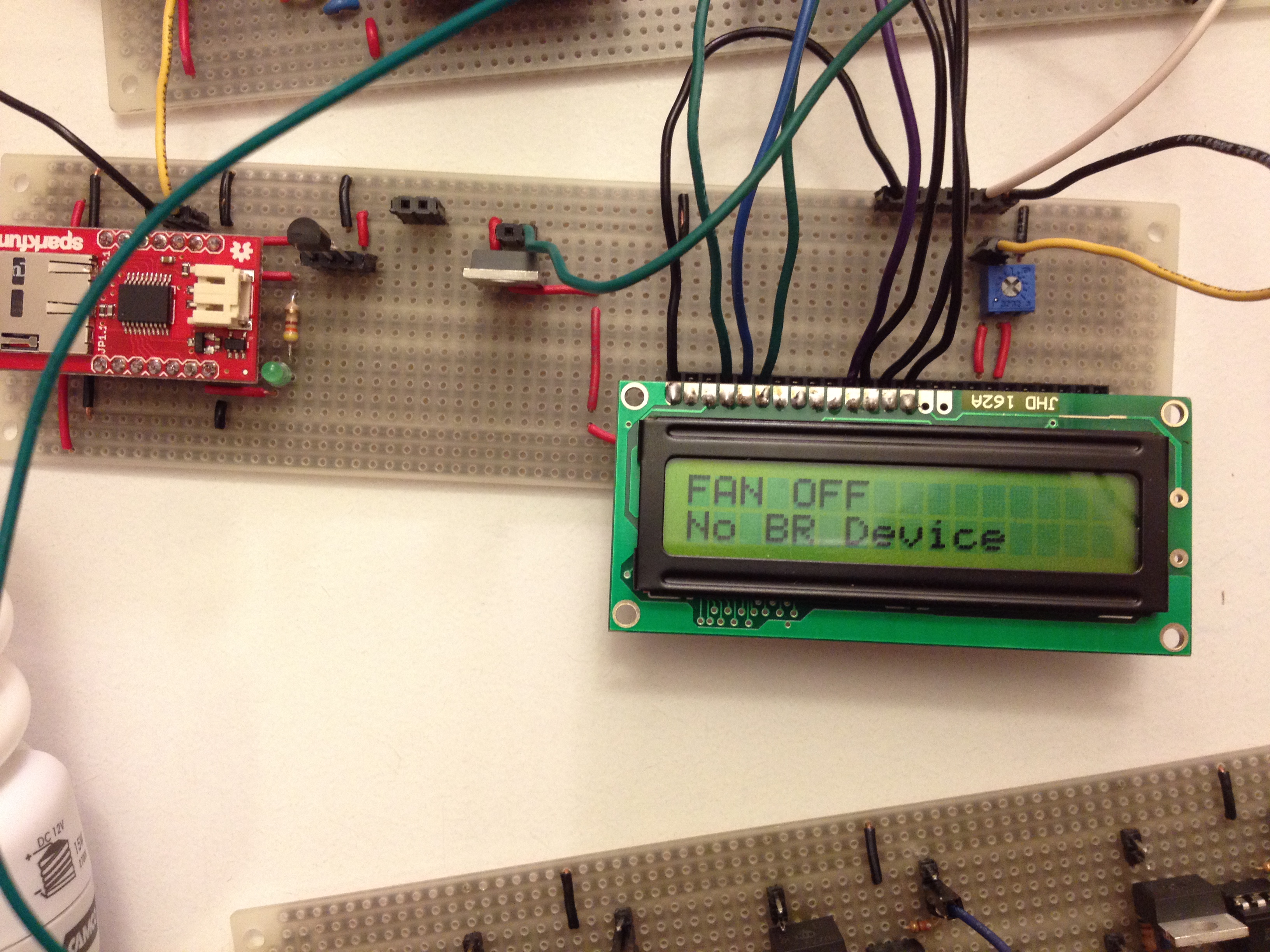
Figure 13:Fan Off Mode
This mode is actived by receving the command of "turn on off". Once our voice of "shut fan" is recognized by the voice recognition chip, the command will send out with a character of "g" through the Xbee from the Atmega 328 and received by Atmega 1284. Once the interrupt service routine is on, the character will be stored in UDR. Atmega 1284 will address what the command is and operate on family appliance. Here, the character is "g", OCR2A will turned to 255 so that fan will be turned off. Meanwhile "FAN OFF" mode will be shown on the LCD screen.
Bedroom On Mode
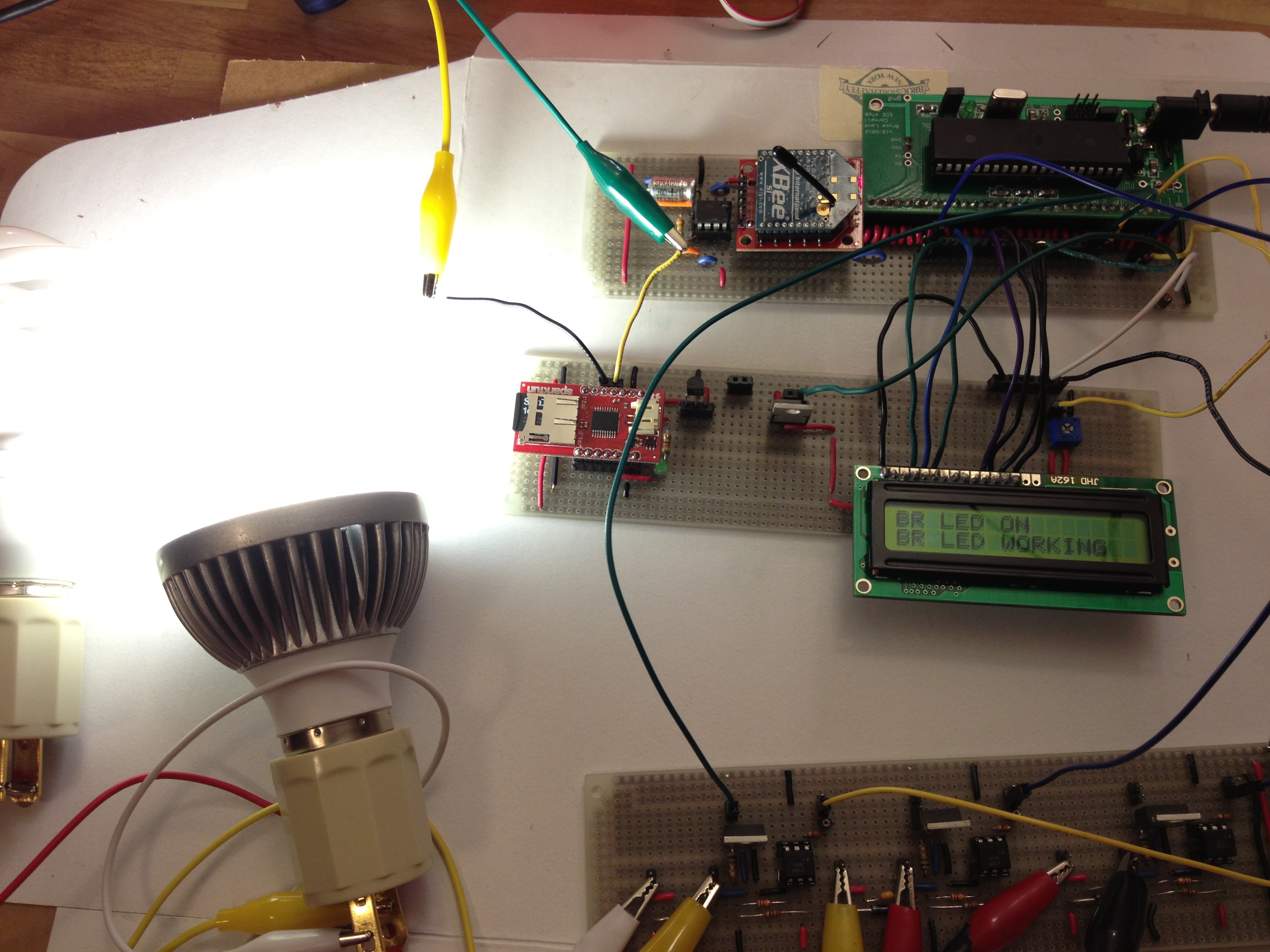
Figure 14:Bedroom On Mode
This mode is actived by receving the command of "turn on bedroom". Once our voice of "turn on bedroom" is recognized by the voice recognition chip, the command will send out with a character of "a" through the Xbee from the Atmega 328 and received by Atmega 1284. Once the interrupt service routine is on, the character will be stored in UDR. Atmega 1284 will address what the command is and operate on family appliance. Here, the character is "a", OCR0A will turned to 10 so that the LED bulb will be on. Meanwhile "BR LED ON" mode which means the LED Bulb in the bedroom is on will be shown on the LCD screen.
Bedroom Dimmer Mode
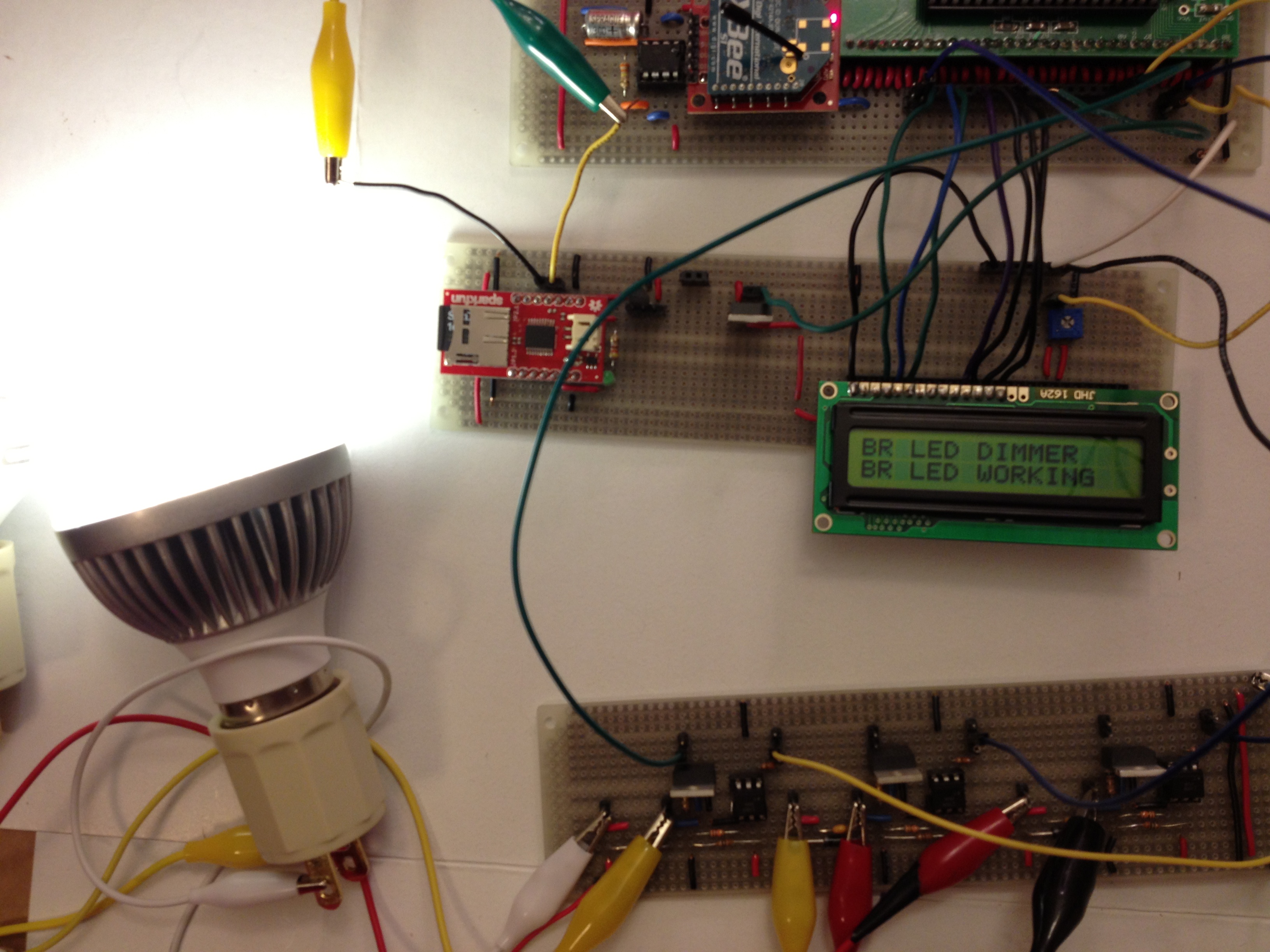
Figure 15:Bedroom Dimmer Mode
This mode is actived by receving the command of "bedroom dimmer". Once our voice of "bedroom dimmer" is recognized by the voice recognition chip, the command will send out with a character of "c" through the Xbee from the Atmega 328 and received by Atmega 1284. Once the interrupt service routine is on, the character will be stored in UDR. Atmega 1284 will address what the command is and operate on family appliance. Here, the character is "c", OCR0A will turned to 200 so that the LED bulb will be dimmer. Meanwhile "BR LED DIMMER" mode which means the LED Bulb in the bedroom is dimmer will be shown on the LCD screen.
Bedroom Off Mode
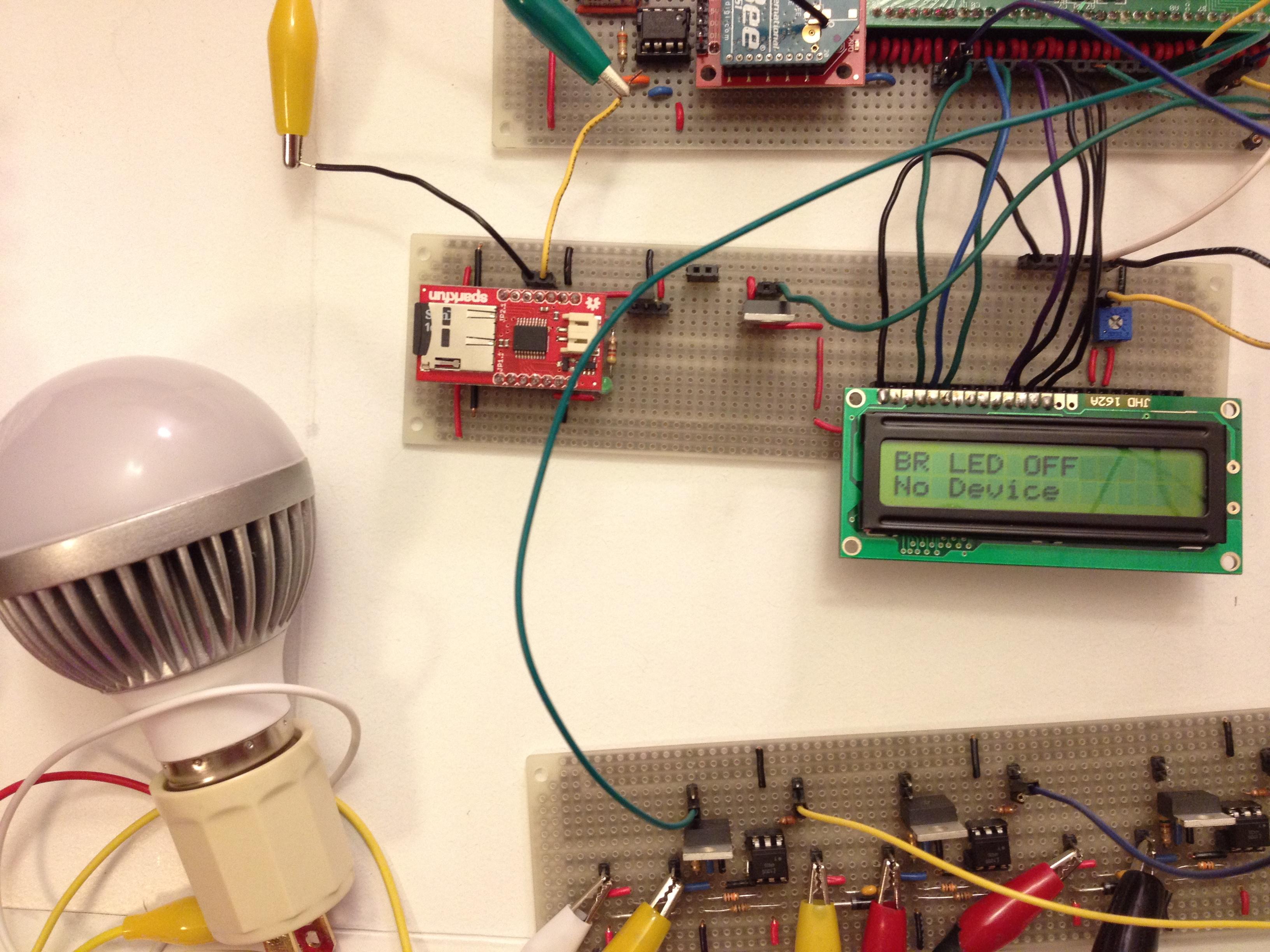
Figure 16:Bedroom Off Mode
This mode is actived by receving the command of "light off". Once our voice of "light off" is recognized by the voice recognition chip, the command will send out with a character of "b" through the Xbee from the Atmega 328 and received by Atmega 1284. Once the interrupt service routine is on, the character will be stored in UDR. Atmega 1284 will address what the command is and operate on family appliance. Here, the character is "b", OCR0A will turned to 255 so that the LED bulb will be off. Meanwhile "BR LED OFF" mode which means the LED Bulb in the bedroom is off will be shown on the LCD screen.
Lounge On Mode
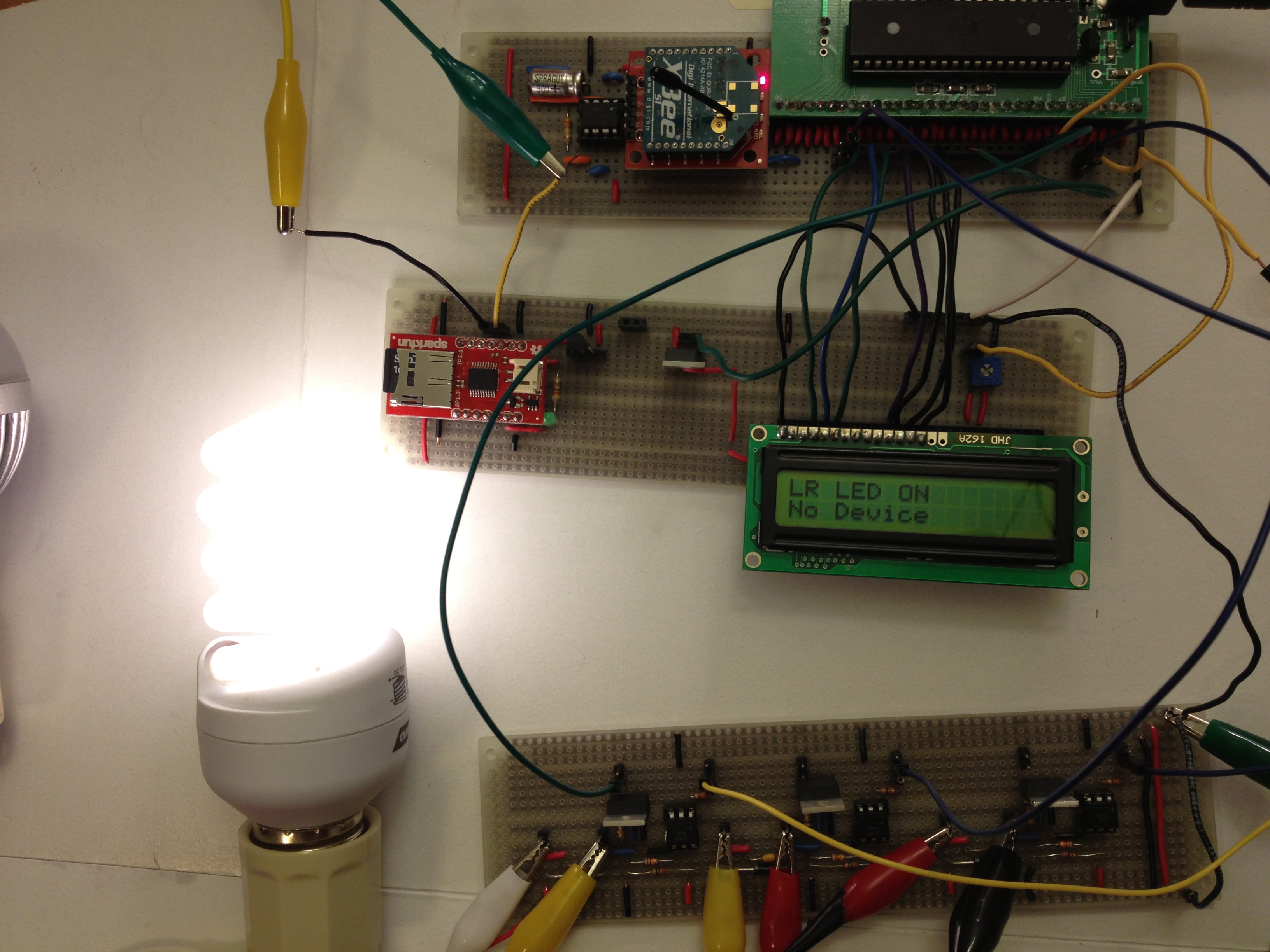
Figure 17:Lounge On Mode
This mode is actived by receving the command of "louge on". Once our voice of "lounge on" is recognized by the voice recognition chip, the command will send out with a character of "d" through the Xbee from the Atmega 328 and received by Atmega 1284. Once the interrupt service routine is on, the character will be stored in UDR. Atmega 1284 will address what the command is and operate on family appliance. Here, the character is "d", OCR1A will turned to 10 so that the LED bulb will be on. Meanwhile "LR LED ON" mode which means the LED Bulb in the lounge is on will be shown on the LCD screen.
Lounge Off

Figure 18:Lounge Off
This mode is actived by receving the command of "turn off louge". Once our voice of "turn off lounge" is recognized by the voice recognition chip, the command will send out with a character of "e" through the Xbee from the Atmega 328 and received by Atmega 1284. Once the interrupt service routine is on, the character will be stored in UDR. Atmega 1284 will address what the command is and operate on family appliance. Here, the character is "e", OCR1A will turned to 255 so that the LED bulb will be off. Meanwhile "LR LED OFF" mode which means the LED Bulb in the lounge is off will be shown on the LCD screen.
Delay off Function
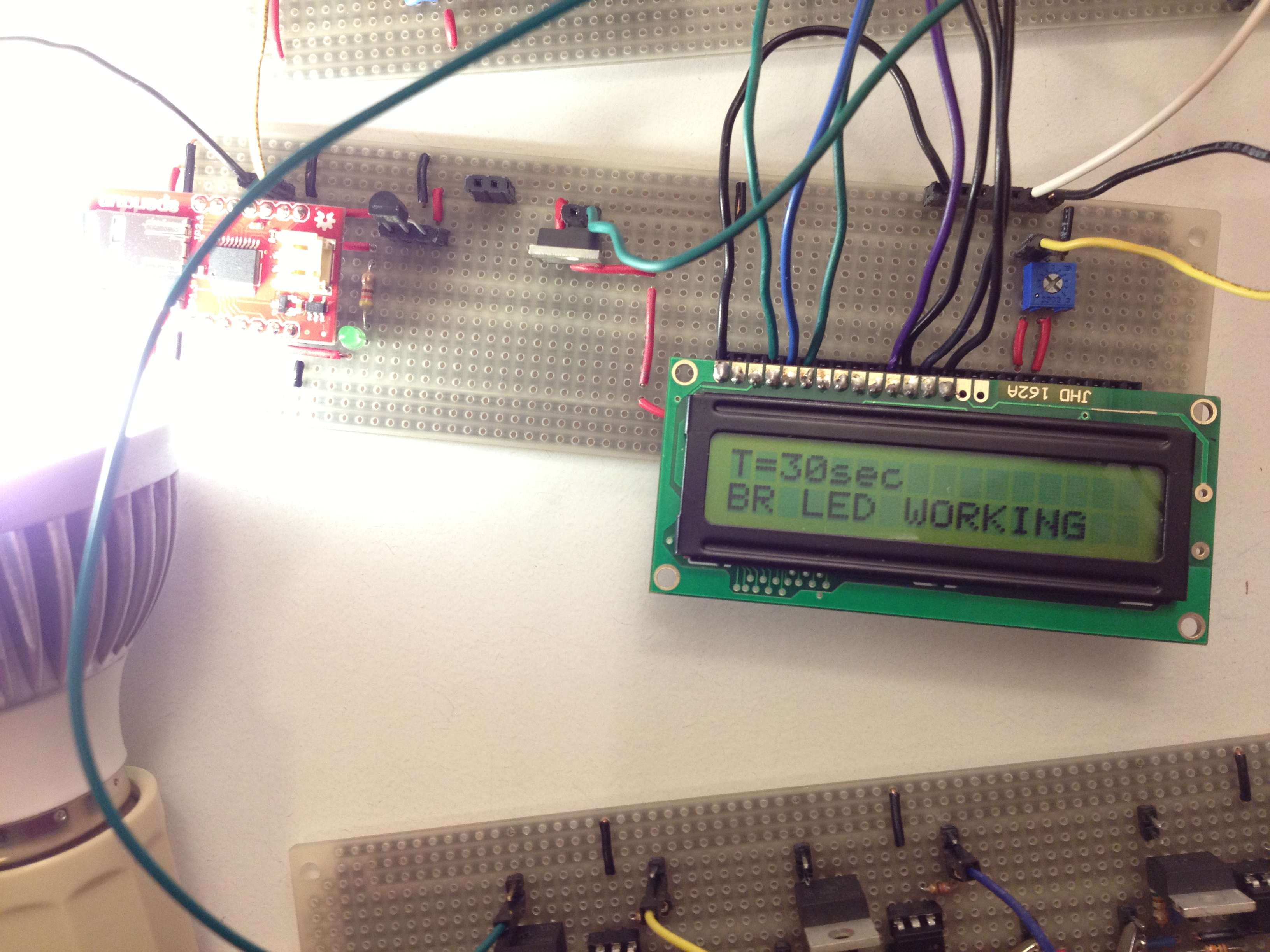
Figure 19:Delay off Function
This mode is actived by receving the command of "bedroom on for 30 seconds". Once our voice of "bedroom on for 30 seconds" is recognized by the voice recognition chip, the command will send out with a character of "i" through the Xbee from the Atmega 328 and received by Atmega 1284. Once the interrupt service routine is on, the character will be stored in UDR. Atmega 1284 will address what the command is and operate on family appliance. Here, the character is "i", OCR1A will turned to 255 so that the LED bulb will be off. Meanwhile "T=30sec" mode which means the LED Bulb in the bedroom is on for 30 sec will be shown on the LCD screen.
Safety and Usability
We use +9V battery to provide the power to CPUs and +12V battery to the whole home device. In this way the low power supply won’t take damage for people or other device. Moreover, we solder the board very carefully , we spemt much time on the board design to make sure all the wires are straight and without cross. On the other hand, we design the fault detection part in the system. The device will show the reminder on the LCD to remind user change the broken lights or fans in time.
For our project, if we set up it at home, it will save much time. We could do more things at the same time without movement of your body. On the other hand, this system will be very useful for the people who is with physical disability. When they enter the room, if the switch too high or too far, they can’t reach it. With the wireless voice control system, they can control the device by the voice instructions.
We imagine for the future life, wireless control would be necessary. People could ask for the device come to help us. People could control them accurately. So our smart home system is a good start for this field research. It will be a good example for the voice wireless system for the future study.
Accuracy
The display on the LCD is very accurate and the only accuracy problem we need to care is about the voice received by microphone. The principle of EasyVR is we need to record the voice commands in it in the first. There is a memory to store the commands. When we send the voice commands for the microphone, the chip will compare the voice commands frequency in memory and the new voice command frequency. Usually, we need a quit environment to get the best effect. If the same person store the voice commands and send it. The chip will catch the command accurate. If the different people do that, there may be a miss match problem. People need to send the same command again.
Conclusions top
Final Thoughts
We realize all the function in our project which we expected at the beginning of the final project. We expected use voice to control the home devices in a wireless system. We could parallel control the different home devices at the same time, such as lights, fan and music. If we have chance to do the same topic next time, we want to control bigger device, such as the TV or air-condition. On the other hand, we could set up the smart home system in the smart cellphone which we could control the home electrical device by talking to cellphone application. One more thing is we want to add the security system at next time by put the sensor near the window to make our home more safety.
Intellectual Property Considerations
We didn’t reuse code or someone else’s design, all of the design is our. We never used our code in the public domain. And all of them are created in the five weeks final project period. We are not the reverse-engineering for our design because we make the goal in the first. We didn’t try to looking for some similar example on the website and to study them. We created our project by discuss and meeting. All the ideas are come from the exchanging idea by partner. For the patent/trademark issues, we must protect the author’s rights. For the code or article on the Internet, we could encrypt them and to make sure people can’t download it and in this way to protect their right. We never had to sign non-disclosure to get a sample part. For the patent and publishing opportunities, we don’t find the similar device on the Internet, but we are still not 100% sure that. If our project could really take more convenience for people, we’d like to publish it.
Ethical Considerations
For our project, there won’t the ethical considerations problems. We think our project is consistent with the IEEE code of ethics. All of them are created by us, both of the hardware and software part. For the purpose of this project, we want to make people’s life more convenient and we use very low power even if there is no harm for people. So there is no much more band influence for society. Actually, our product will bring much more benefit for people for the future 10 years.
Appendices top
A. Parts List and Costs
We ordered all electronic parts from sparkfun.com. And we have two different plan, onwe is control the whole system by voice instruction and the second plan is to control the whole system by computer
Plan 1 - Voice Control
| Category | Item | Vendor | Unit Cost | Quantity | Total Cost |
|---|---|---|---|---|---|
| Electronics | Xbee | Donated by bruce | $0.00 | 1 | $0.00 |
| Preowned | $0.00 | 1 | $0.00 | ||
| EasyVR Shield - Voice Recognition Shield | Sparkfun.com | $49.95 | 1 | $49.95 | |
| WEV020-SD | Sparkfun.com | $19.95 | 1 | $19.95 | |
| ATmega1284 | ECE 4760 Lab | $5.00 | 1 | $5.00 | |
| ATmega328 | preowned | $0.00 | 1 | $0.00 | |
| custom PC board | ECE 4760 Lab | $4.00 | 1 | $4.00 | |
| LCD Display (2x16) | ECE 4760 Lab | $8.00 | 1 | $8.00 | |
| Voltage regulator | ECE 4760 Lab | $0.00 | 2 | $0.00 | |
| fan | ECE 4760 Lab | $0.00 | 1 | $0.00 | |
| lights | preowned | $0.00 | 2 | $0.00 | |
| lights adapter | preowned | $0.00 | 2 | $0.00 | |
| 4N35 | ECE 4760 Lab | $0.00 | 3 | $0.00 | |
| BUZ73 | ECE 4760 Lab | $0.00 | 4 | $0.00 | |
| resistor | ECE 4760 Lab | $0.00 | 17 | $0.00 | |
| 10K trimpot | ECE 4760 Lab | $0.00 | 1 | $0.00 | |
| Speaker | ECE 4760 Lab | $0.00 | 1 | $0.00 | |
| Connections | Solder Board (6 inch) | ECE 4760 Lab | $2.50 | 3 | $7.50 |
| Wire | ECE 4760 Lab | $0.00 | N.A. | $0.00 | |
| Total | $94.4 |
Table 2:Voice Control System Budget
Plan 2 - Computer Control
| Category | Item | Vendor | Unit Cost | Quantity | Total Cost |
|---|---|---|---|---|---|
| Electronics | Xbee | Donated by bruce | $0.00 | 1 | $0.00 |
| Preowned | $0.00 | 1 | $0.00 | ||
| WEV020-SD | Sparkfun.com | $19.95 | 1 | $19.95 | |
| ATmega1284 | ECE 4760 Lab | $5.00 | 1 | $5.00 | |
| custom PC board | ECE 4760 Lab | $4.00 | 1 | $4.00 | |
| LCD Display (2x16) | ECE 4760 Lab | $8.00 | 1 | $8.00 | |
| Voltage regulator | ECE 4760 Lab | $0.00 | 2 | $0.00 | |
| USB adapter | Sparkfun.com | $24.95 | 2 | $24.95 | |
| fan | ECE 4760 Lab | $0.00 | 1 | $0.00 | |
| lights | preowned | $0.00 | 2 | $0.00 | |
| lights adapter | preowned | $0.00 | 2 | $0.00 | |
| 4N35 | ECE 4760 Lab | $0.00 | 3 | $0.00 | |
| BUZ73 | ECE 4760 Lab | $0.00 | 4 | $0.00 | |
| resistor | ECE 4760 Lab | $0.00 | 17 | $0.00 | |
| 10K trimpot | ECE 4760 Lab | $0.00 | 1 | $0.00 | |
| Speaker | ECE 4760 Lab | $0.00 | 1 | $0.00 | |
| Connections | Solder Board (6 inch) | ECE 4760 Lab | $2.50 | 3 | $7.50 |
| Wire | ECE 4760 Lab | $0.00 | N.A. | $0.00 | |
| Total | $69.4 |
Table 3:Computer Control System Budget
B. Source Code
The microcontroller soucre code is available code_on_ATmega1284 and code_on_ATmega328.
C. Specific Task Breakdown
| Jiyuan Wang | Both | Sheng Zhang |
|---|---|---|
| Microcontroller code | Debugging | Soldering, hardware implementation |
| Import the voice instructions | Website content | Website graphics |
| Hardware design | Website formatting |
Table 4:Task Breakdown
References top
This section provides links to external documents, code, and websites referenced and used throughout the project.
References
Acknowledgements top
We would like to thank Dr.Bruce Land to teach us how to solder the board and to help us to debug our program. He taught us how to debug the circuit problem by oscilloscope and help us to fix the timer problems. Thanks him to teach us the whole semester with the microcontroller knowledge. We’d also like to thank Amrit Singh and Michael Kilzer to help us to looking for the problem with our circuit and program. And want to thank our TA Terry Kim, too. She asked for us to hand on the weekly report to help us remember what we did before which is a good habit for our future study.
Team Members top
 |
Jiayuan Wang
M.Eng Student, 2012
Electrical and Computer Engineering
Interests:
Embedded System, Wireless Sensor Network, Medical Instruments |
 |
Sheng Zhang
M.Eng Student, 2012
Electrical and Computer Engineering
Interests:
Embedded System, Control System, Robots, Analogy Circuits |