An Introduction top
"Clap-E, A sound follower robot that follows you everywhere you go as long as you are clapping"
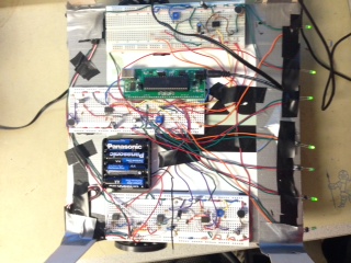
Final Prototype of Clap-E

For the ECE 4760 final project, we designed and built a sound follower robot named Clap-E. As its name implies, Clap-E receives a clap sound and moves toward the source of clapping. It has the ability to change its position after multiple claps and readjusts its path toward the source of sound. We didn’t want our robot to be sensitive to human voice or other “common” surrounding sounds, so it detects mainly clapping. However, if someone generates a sound as loud and sharp as the sound of clapping , Clap-E can follow him or her.
High Level Design top
Rationale and Source of Our Project Idea
Robotics is a progressive field which is evolving every day. Our inclination to build a project that helps us gain experience in both hardware and software, drove us towards designing a sound follower robot.
The biggest challenge and the first step, was to identify the direction of sound. Three sensors were used in the final design to detect the sound coming from all directions. Our initial design was to use the difference in amplitudes of voltages received by the sensors to detect the direction of sound. The idea was that the microphone sensor closer to the sound source receives a sound of greater amplitude when compared to the sensor farther away from the source. However, this does not work accurately as the sensors are separated only by a distance of 23 cm, which is not enough for the sound waves to be dampened.
Background Math
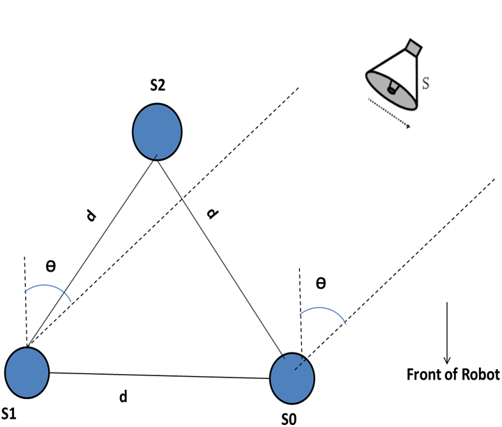
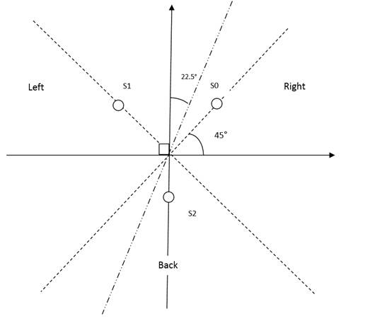
Our next approach was to measure the difference in the ‘Time of Arrival’ of the sound waves between two microphones. This can be calculated using simple trigonometry. The sensors were arranged as shown in figure 1. The sound waves were assumed to be in parallel with each other since the sound source is at negligable distance from the sensors. In figure 1, S1 and S0 are the microphone sensors seperated by a distance ‘d’. When the sound source ‘S’ is closer to sensor S0, sound waves will have to travel an additional distance of (d *sin Ѳ) in order to reach sensor S1. Ѳ is the angle between the sensor and the source. From simple speed theory, we have:
d*sin Ѳ = ΔT * V ----------------------------------------------------------------------------------------------- (1)
where,
ΔT is the difference in time of arrival of sound to the two sensors, V is the standard velocity of sound in air (approximately 343m/s), d*sin Ѳ is the distance travelled by the sound wave

Logical Structure
Using equation (1) and simple coding logic, we can compute the direction of the sound source ( either left or right) and angle of the sound source from the sensor ( between 0 – 90 degrees). The position of the source is then defined by a pair of two elements (Left/Right, angle). However, using just two sensors, fails to identify whether the sound source is located forward or backwards. In other words, we wouldn’t be able to decide whether sound was generated in front or behind the robot. This problem was solved by introducing a third sensor S2. The third sensor improved significantly the design and enabled us to identify the sound source in a field of 360 degrees. Figure 2 shows the 3-sensor-triangular arrangement that has been adopted in the project . The difference in arrival time (for calculating the angle ‘Ѳ’) is measured between S1 and S0 only. S2 is strictly used to determine whether sound was generated in front or behind the robot.
The final circuitry used for the sensors is shown in figure 3. The analog data from sensor S0 is fed into an amplifier. The voltage gain of the amplifier is set to 20 by using R1 = 2k and R2 = 10k. The amplified voltage is passed through a peak detector circuit, which is internly connected to a voltage comparator. We have used LM358 ICs which contain two op-amps for each sensor to form the amplifier and the comparator circuitry. The trimpot is adjusted such that, the reference voltage is 2.56V.
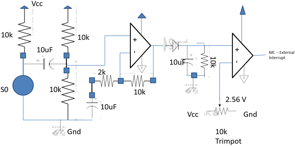
The comparator’s output for one clap sound, as observed on the oscilloscope is expected to look as shown in figure 4. The algorithm to determine the direction of the sound source is given on figure 5a, 5b, 5c, 5d and 5e. The three external interrupt pins of the microcontroller were used. INT0, INT1 and INT2 are activated to generate an interrupt when there is a rising edge. The output of the comparator in the sensor circuit, as shown in figure 3, is connected to the external interrupts. Whenever sound is detected by the sensor, a rising edge is generated at the output of the comparator and the corresponding external interrupt is invoked.
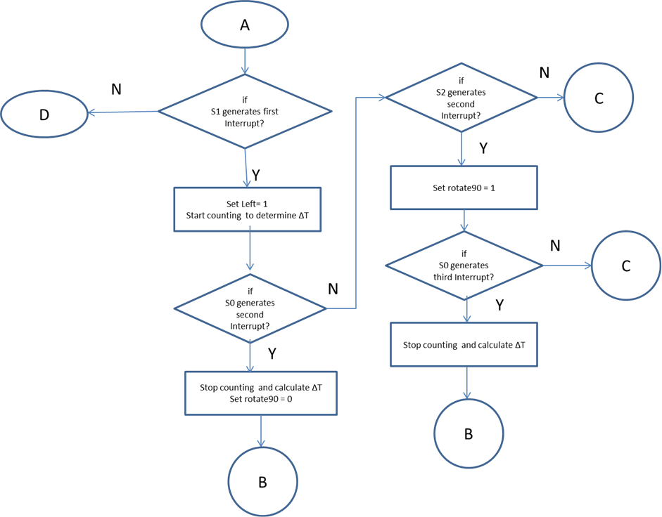

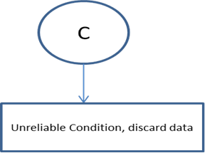
The original position of the sound source is determined by checking which sensor triggered the first interrupt. If S0 generates the first interrupt, the system understands that the source comes from the right. However, the robot doesn’t know if the source is at an angle greater than 90 degree from the front of the robot. To solve this issue, we must also consider the sensor that triggers the second interrupt. If S1 generates the interrupt before S2 (Back sensor), then the sound source lies within 90 degrees from the front of the robot. However, if S2 interrupts before S1, then the source lies at an angle greater than 90 degrees from the front of the robot. Similarly, if S1 interrupts first, then the source is to the left, and by considering the order of generation of the interrupts for S0 and S2, we can certainity determine the angle of the source from the front of the robot. The last condition would be that S2 is interrupted first, which means that the sound source is at an angle greater than 90 degrees from the front of the robot. The direction, i.e left or right depends on whether S1 or S0 interrupts second respectively.
There is also the scenario where multiple interrupts are invoked at the same time. For example, if S0 and S1 receive the sound at the same moment, the angle Ѳ is 0 degrees. If all three interrupts are invoked at the same time, it implies that the source is equidistant from all three sensors, this can be treated as a ‘destination reached’ state. This multiple interrupt situation has been handled by checking the interrupt flags, INTF0, INTF1 and INTF2 of the EIFR Register.
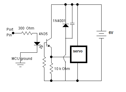
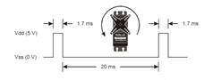
After determining the angle Ѳ, which defines the direction of the sound source, it was time to rotate the robot in the direction of sound. The drive system of the robot consists of three wheels, two of which are driven by servos and the third wheel constitutes the support wheel. Continuous rotation servos were used to achieve the motion of the wheels. The servos require pulses of width in a range between 1.3 ms and 1.7 ms spaced with intervals of 20 ms. The datasheet of the motors is attached to the appendix. The trimpot of the servos is adjusted so that 1.5 ms pulse acts as the dead centre (i.e no rotation). A 1.7ms pulse rotates the servo anticlockwise at full speed, while a 1.3 ms pulse rotates the servo clockwise at full speed. The opto-isolator circuitry used for the servo rotation is the same as the one that was used in Lab 4 of the ECE 4760 course, with a few modifications. The Servo driver circuit is shown in figure 6. The modifications were required since the speed and/or direction were changed after modifying the pulse width.
After having carefully researched on different steering systems, our final decision was to rotate the robot to a specific, generic angle. The right wheel has to rotate clockwise while the left wheel rotates anticlockwise at the same speed so that the robot moves in a straight line, either forward or backwards. When both the wheels are rotated in the same direction, the robot rotates.
The idea to use triangular model for sound sensors was obtained from the paper by Mr. Nilesh Goel. The paper has been included under references[1]. However, we decided to keep the logic simple and consider only 2D plane instead of 3D. The logic used by us has already been described. However, for a better understanding, you can refer to Mr. Goel’s paper attached in this report.
Hardware and Software Tradeoffs
1. The greatest software trade-off is that our software stalls in the same loop when the motor is running. This could be avoided using an operating system and different processes to run each thread i.e the motor and the sensor. We have not used an operating system because the robot has a single functionality, which is to move when it senses a ‘Clap’. Since motor control is dependent on the sensor data, we have avoided using TRT and used just a flag variable to register data. Another reason for not using TRT was to avoid the implementation of an additional interrupt, Timer1 TRT interrupt, which may cause an overhead on the microcontroller.
2. We are unable to detect the distance of the sound source from the robot. Therefore the robot may need to be fed with sound multiple times untill it reaches the source.
3. The robot may move past the sound source and then return and move back again. Since our design does not rely on distance calculation of the robot from the source, the robot moves based on 1 standard unit distance. 1 unit is approximately 30 centimeters.
4. Three breadboards were used instead of lighter, cheaper PCB board, which added additional unneccessary budget overhead on the project. Since we had a large number of circuitry to be soldered, we decided to trade budget for time. So we compromised on this part and utilized the time we had to make the robot look cooler.
Standards
The C code in our project abides by the C Language standards set by the ANSI (American National Standards Institute) and the 1666-2011 IEEE Standard System Language. Our projects is also conform to the 1451.2-1997 IEEE Standards for Transducers for Sensors and Actuators.
Copyrights
We hereby attest that we acknowledged and have listed all the documents used for this project in the reference section of the appendix.
Hardware top
The hardware consists of two main circuits. The sensor circuitry and the servo driver circuitry.
Sensor Circuit:
An overview of the sensor circuitry has already been provided under the high level design section. The sensors used to detect sound are microphone sensors. Three sensors were placed at the three vertices of an equilateral triangle of sides 23 cm. A pictorial representation was provided in figure 2. Each sensor circuitry consists of one low power dual operational amplifier LM358 and a peak detector circuit which is provided under Figure 3. The two op-amps of LM358 are used as amplifiers with a gain of 20 and a comparator with Vref = 2.56V. The output of the comparator is fed into the MCU Port D2, D3 and B2 for sensors S0, S1 and S2 respectively. A positive edge on the output of the comparator when a ‘clap’ is detected, generates an interrupt INT0, INT1 or INT2 for S0, S1 or S2 respectively. A 9V battery was used to power the microcontroller instead of a cheaper power supply. Despite the price difference (shown in Appendix B), it was more convenient to use the battery rather than the power supply to enable the robot to move in all direction without being stuck in the power supply wire.
Servo Driver Circuit:
The second circuit is the servo driver circuit. As previously stated, this circuit is similar to LAB4 opto-isolation circuit used in ECE4760 course. An external supply of 6V is used to power the Servo. The Servo is connected in parallel to a capacitor of 0.1 uF (ceramic not electrolytic) and a Diode (1N4001) to eliminate spikes when the Servo is switched off. You may view the circuit on figure 6. The Servo is completely isolated from the Microcontroller port using the opto-isolator 4N34. The speed and direction of rotation of the servos are controlled by the PWM signals from the microcontroller via PORTA.0 and PORTA.1. As already stated, the dead/zero point of the servo is set at 1.5 ms pulse. The servo rotates clockwise at full speed (50 rpm) when 1.3 ms pulses are applied with intervals of 20 ms. The servo rotates clockwise at full speed (50 rpm ) when 1.7 ms pulses are applied with intervals of 20 ms. The sensor circuitry and the servo driver circuitry are finally integrated using Atmega1284P microcontroller. All the circuits were built on breadboards.
Chassis of the robot:
We had two options for building the robot. The first one was to buy a robot kit which ended up being very expensive and inconvenient because the affordable kits we found didn’t contain all the elements needed to build the desired robot. Therefore, we decided to build a “green” robot with the material we already have. We used cardboard boxes and leds. All we had to buy were wheels, batteries and servos.
Software top
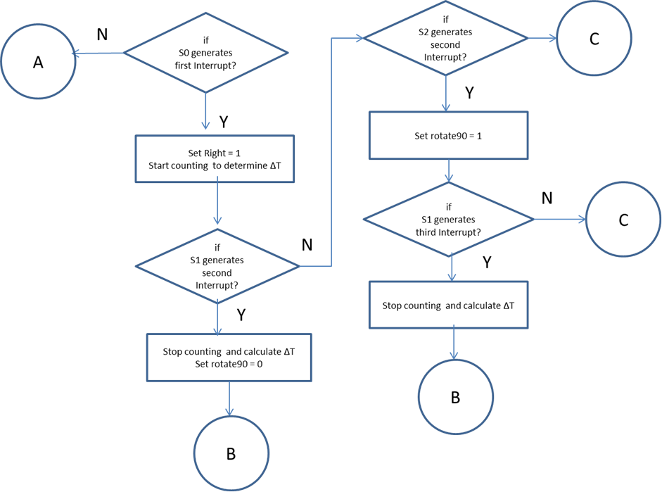
Algorithm for position of sound source:
The software uses the three external interrupts INT0, INT1 and INT2 triggered at rising edge to calculate the difference of sound arrival time. The flow diagram for the software are provided in Fig 5a to 5e. The position of the sound source is determined by checking which sensor triggered the first interrupt.
If S0 generates the first interrupt, the system understands that sound came from the right and the counter is started to determine ΔT. Then, if S1 generates the second interrupt before S2 (Back sensor), the count stops and ΔT is computed. However, if S2 generates the second interrupt before S1, then the source lies at an angle greater than 90 degrees from the front of the robot. ΔT can then be measured and the angle calculated.
Similarly, if S1 generates an interrupt first, the system understands that sound came from the left and the counter is started to determine ΔT. Then, if S0 generates the second interrupt before S2, the count stops and ΔT is computed. However, if S2 generates the second interrupt before S0, then the source lies at an angle greater than 90 degrees from the front of the robot. ΔT can then be measured.
The last condition would be that S2 is interrupted first, which means that the sound source is at an angle greater than 90 degrees from the front of the robot. The direction, i.e left or right depends on whether S1 or S0 interrupts second respectively. So once again, the system checks which one of S0 or S1 generated the second interrupt.
The software uses two timers of the microcontroller. Timer 0, which runs at full speed with a prescaler set to 1 to calculate the difference in time of arrival accurately. Timer 2 is used to generate an interrupt every 100 us. The latter is used to generate PWM signals for servo motor control on PORTA.0 and PORTA.1.
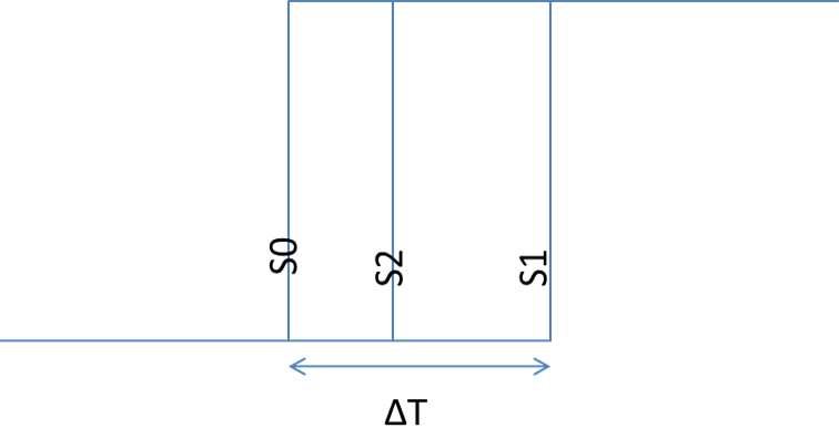
Once the 3-sensor circuit ready, it was possible to calculate the difference in time of arrival between the sensors using the oscilloscope. The maximum value of ΔT was approximately 900 us on the oscilloscope. Therefore, a high resolution was required. Timer 0 was set to be a counter for this purpose. This provided a resolution of 0.0625 us.
It was not only important to calculate the angle Ѳ which lies between 0 and 90 degrees, but also to determine the direction from which the source is originating. Therefore, we introduced three main variables Left, Right and Rotate90 respectively associated with the left sensor, the right sensor and the back sensor. By determining if the sound comes from left, right, back, we were able to determine which quadrant the sound came from. The 3 variables were updated in the ISRs of the External Interrupts. The values of these variables depended on which Interrupt was triggered first. Whenever an interrupt was triggered first, the corresponding variable is assigned the value of ‘1’ and ‘0’ otherwise.
Angle Calculation Algorithm:
Determining the ‘Time of Arrival’ of sound waves naturally enabled us to compute the angle between the microphones and the sound source. In fact, the angle can be calculated using simple trigonometry as shown on figure 2. The sound waves were assumed to be in parallel with each other since the sound source is at a negligable distance from the sensors. In the figure, S0, S1 and S2 are the microphone sensors placed in an equilateral configuration seperated by a distance d=23 cm. As stated previously, we used the following equation to calculate the angle from the measured time ΔT:
Ѳ = arcsin(ΔT * V/d) ----------------------------------------------------------------------------------------------- (2)
The mat.h library calculates angles in radians so we had to convert the angle to degrees.
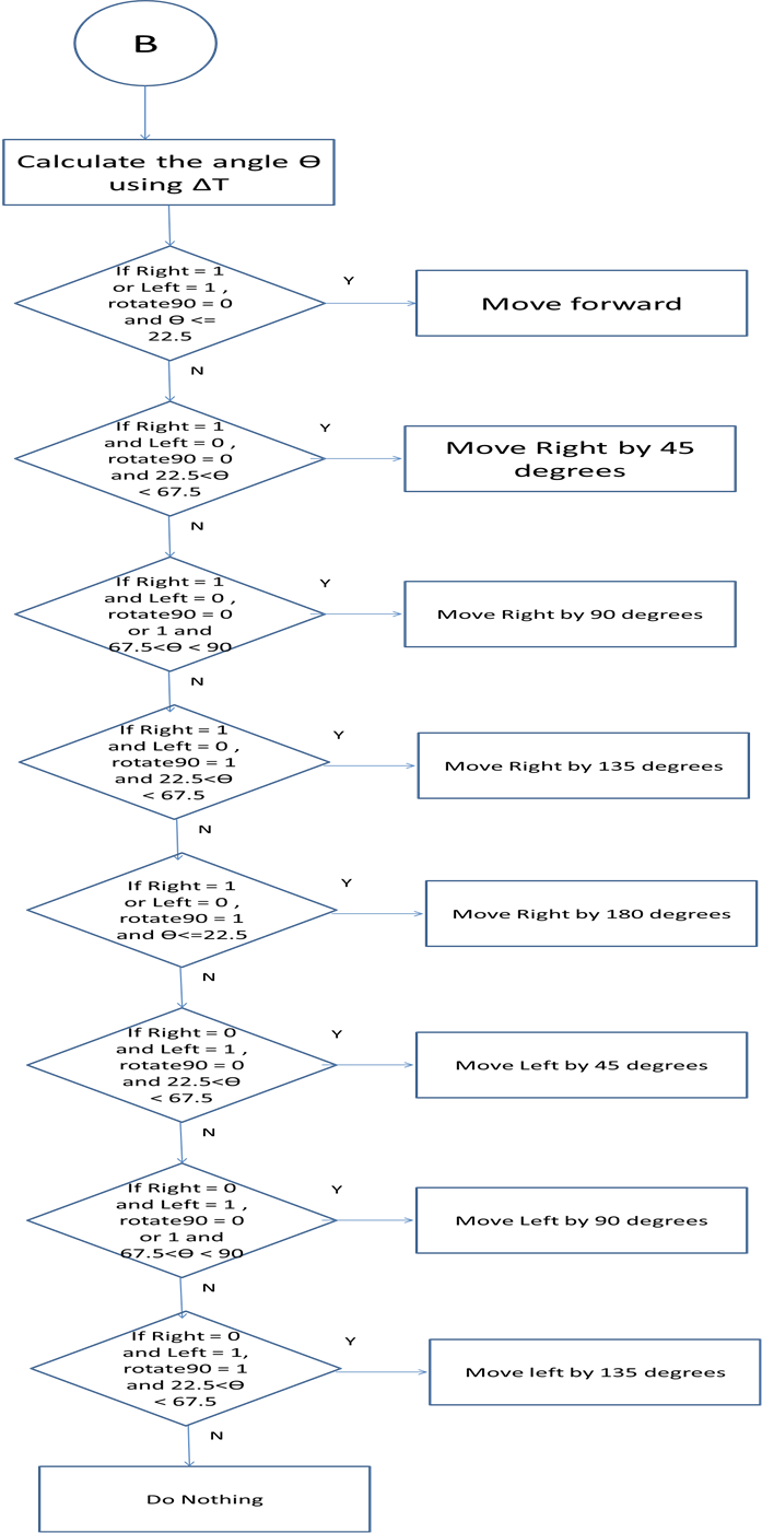
Servo Control and Motion Algorithm:
The variable “Motor_state” has been used to store the state of the motor. In other words, it defines the direction of displacement of the robot and helps determining the direction of rotation of each motor. As stated previously, the direction of rotation of the robot is characterized by two values: Right/Left and the angle of rotation. 4 variable were used to decide for the value of Motor_state: rotate_90, right_dir and left_dir and Angle. For example, if both right_dir and left_dir have a value of ‘1’ while rotate_90 has a value of ‘0’, this means that the sound source is equidistant from the left and right sensors but farther away from the back sensor. So the robot has to move forward. So, the Motor_state variable will be set to FWD (forward). The same logic was applied to all other states of the motors. We set 8 standard angles at which the robot can rotate as shown in figure 8: 0°,45° (clockwise and counterclockwise) ,90° (clockwise and counterclockwise),135° (clockwise and counterclockwise) and 180°. Therefore, we had to define a range of angles covered by each standard angle value. In other words, if the clap sound comes from an angle comprised between 0 and 22.5 degrees for example, the robot will arbitrarely move 0° forward. If the clap sound comes from an angle comprised between 22.5 and 67.5 degrees, the robot will arbitrarely move 45° clockwise. The values of the three variables right_dir, left_dir, rotate_90 as well as the measured angle are shown in table 2 under the results section.
Testing Strategy and Confronted Issues:
Hardware was built and tested first. We started building the circuit considering 2 sensors only. The sound signal was amplified by 10 then by 20 because we wanted to generate a signal that would enable us to compute the time difference ΔT but we didn’t want the system to be sensitive to voices. One of the robot’s requirements was to respond to claps only or louder and sharper sounds. The values of resistances chosen for the circuit were the key to a good sound amplification and detection. A probe was connected to the output of each comparator to measure ΔT on the oscilloscope.
After getting a prototype of the 2-sensors’ circuit used for sound detection, we decided to build the 3-sensors’ circuit. But first, each sensor was tested independently to make sure that the sound signal was amplified accordingly and that the peak detector signaled only the first peak of the amplified signal. The 2 front sensors worked perfectly but the third one was not amplified. This was due to the bad quality of the breadboard used. Indeed, the breadboard was shorting one of the connections in the circuit. This was fixed by just changing the placement of the connection on the breadboard.
After verifying that the sensors’ circuit was operational using the oscilloscope, the next step was to test the software. Putty was used to print the direction of sound (right, left or back) as well as the time difference and angle value in degrees. Angles were all lying within a range from 0 to 70 degrees. When the sound came from a clap at an angle of 90 degrees, the measured “arriving time” was always very large which confused the computer and resulted in an incorrect computation of the angle Ѳ. Instead of 90 degrees, Putty always displayed “nan”. The reason for getting such a large number for “arrival time” is probably bouncing sound waves. This problem was solved by setting the angle to 90 degrees whenever the arrival time was greater than 670. The formula was used as follows to find the number 670. ΔT = [23*10^(-2)]*sin(90)/(343) = 670 us
Before combining motors and sensors, it was essential to test motors independently to understand how they work and how to write the code to connect them to the rest of the circuit. The motors had a problem rotating at the expected speed due to current overload on the power supply. The problem was solved by using the power supply of 6V rather than 20V since the current available was higher. Another problem confronted was that one of the motors stopped rotating after 3 complete rotations while the second one was still rotating. This was due to an incorrect initialization of Port A of the microcontroller that controls motors. In order to move the robot forward, the two motors have to rotate in opposite directions. In reverse, when the robot rotates, the motors have to rotate in the same direction. When testing the rotation of the motor, we tested forward motion by setting the low pulses of both motors to 200 and the high pulse of the right motor to 13 while the left one to 17. To test backward motion, we set the low pulses of both motors to 200 and the high pulse of the right motor to 17 while the left one to 13. To test the rotation of the motor either clockwise or counter-clockwise, both motors’ low pulses are set to 200 and both motors’ high pulses are set to 13 or 17 as shown on figures 9 and 10. However, when the robot is either moving forward or backwards, the motors don’t rotate at the exact same speed. We solved this problem by setting one motor’s low pulse to 204 while the other motor’s low pulse was kept to be 200 in the case where the robot moves either forward or backwards. Nothing was changed for the case where the robot has to rotate.

The hardware required a lot of wiring. One loose connection would suffice to the failure of the whole system. Therefore, the wiring process was very tedious and primordial to the success of this project. Testing the functionality of the whole system was not as complicated and tricky as testing the different circuits seperately. Indeed, after connecting the microcontroller to the motors circuits and the sensors circuits, the robot started working successfully. The only parameters that we had to modify were the times it took for the robot to rotate or move forward or backwards.
Results top
Speed of Execution
The motion of the robot is triggered by interrupts so Clap-E is very receptive to clap sound. It responds almost instantaneously to the sound of clapping. It is in fact a matter of milliseconds.However, if the clap is more than 2 meters away from the robot, the latter cannot respond to the sound due to the quality of sensors with low sensitivity.
Accuracy
The Robot moves successfully toward the direction of the clap. Clap-E has the ability to rotate at 8 specific angles as shown in the following table:
| Angle between sound source and sensor | Robot displacement |
|---|---|
| 0 < Ѳ < 22.5 (either left or right) | Move forward |
| 22.5 =< Ѳ < 67.5 (either left or right) | Rotate 45 degrees (right or left) and move forward |
| 67.5 =< Ѳ <112.5 (either left or right) | Rotate 90 degrees (right or left) and move forward |
| 112.5 =< Ѳ < 157.5 (either left or right) | Rotate 45+90 degrees (right or left) and move forward |
| 157.5 =< Ѳ < 180 (either from left or right) | Move backward |
You may also refer to figure 8 to have a pictorial view of this mechanism. The robot has the capacity to change direction while moving whenever there is a new clap. So Clap-E adjusts his trajectory based on sound origin at any moment.
The values of the three variables left_dir, right_dir, rotate_90 as well as the measured and actual angle are shown in table 2 below. Putty displays the following values when the robot has determined its direction of rotation. The mean square error between the angle of sound source and the computed angle is 1.95% which is negligible.
Measured Values |
Actual Values |
Error |
|||
|---|---|---|---|---|---|
| Left direction | Right direction | Rotation_90 | Angle (degrees) | Angle (approximation) | Error (%) |
| 1 | 0 | 0 | 10.1 | 10 | 0.99 |
| 1 | 0 | 0 | 42.74 | 45 | 5.29 |
| 1 | 0 | 1 | 90 | 90 | 0 |
| 1 | 0 | 1 | 90+42.4 | 135 | 1.96 |
| 1 | 1 | 1 | 90+90 | 180 | 0 |
| 0 | 1 | 0 | 42.67 | 45 | 5.46 |
| 0 | 1 | 1 | 90 | 90 | 0 |
| 0 | 1 | 1 | 90+36.7 | 135 | 6.55 |
| MSE | 1.95 | ||||
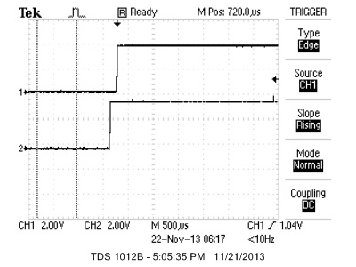
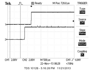
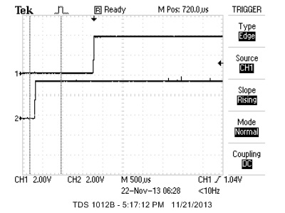
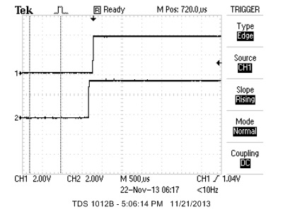
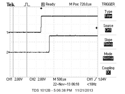
The arrival time was measured as shown on the oscilloscope screen shots on figures 10 to 17. Channel 1 was connected to the output of the comparator of the left sensor while channel 2 was connected to the output of the comparator of the right sensor. On figure 10 for example, the signal arrives approximately at the same time to the left and right sensors so the robot will move forward. On figure 11, the sound signal arrives to the right sensor 500 us earlier than to the left sensor. Therefore, the robot will rotate 45 degrees to the right. The logic is similar for the rest of the graphs.
We could have chosen to be more accurate by making the robot turn at a more precise angle depending on the position of the source. For example, we could have made Clap-E turn every 22.5 degrees instead of every 45 degrees. It would have been very interesting to test what is the smallest rotation angle of the robot.
Safety
The robot as well as the procedures to build it are very safe. The voltage used doesn't exceed 6 Volts and the current needed is below 3 amps. With such low ratings for current and voltage, the user is safe from harm. All wires and circuits have been inserted in a box so that the user can touch the circuitry only if he intends to by opening the box. The circuits are neat so that if the designer or user wants to make modifications to the circuit, it would be safe and easy. Clapping mutliple times was a necessary procedure for testing the robot even if it might have bother our surrounding.
Usability
Clap-E was mainly designed for kids to play with. The procedure is fairly simple; the only thing the kid has to do is clap. However, Clap-E has the potential to be implemented with high quality sound sensors and it can be reprogrammed to detect voices and possibly find people or lost children in places where sight would be useless (such as in dark rooms or at night).
Aesthetic
For aesthetic, the eyes of Clap-E are red LEDs that blink whenever “he’s” in motion. There are also 8 green leds that blink sequentially to make him look “cooler”. We wanted to make Clap-E look “futuristic”, so he has a metallic silver color and all the circuits are in a closed box. We tried to put all the circuits and wires in a closed box but the sensors were not detecting sound waves as well as outside the box. Therefore, a good trade-off was to put all the circuits in an open box as shown on the picture of the robot and on figure 10.
Conclusions top
Did Our Design Meet Expectations?
Clap-E met the expectations knowing that he follows the clapping sound and is able readjust its position to a new clap. However, the sensors are incapable of detecting a source that is farther than 2 meters away because they are not powerful enough. The robot’s detection of the clap source position could have been even more accurate if we had used microphones in a 3D configuration instead of 2D. But this means that we would need more sensors to enable us to calculate angles in 3D space. The math would also be very different.
One other very cool feature that we could have added to our robot was a light following option. We would just have had 4 photodiodes to detect the level of light intensity in all directions. The robot would detect light when it is trapped in a complete dark room. We wanted to combine both light and sound detection. The difficulty here is that we wouldn’t have enough ports for sensors and we would have gone over budget. We would have to use kernel TRT to combine both light and sound sensing. We wanted to finish the project in time so we restricted our objective to sound detection. Additionally, Clap-E would have had a different name then.
This project was very fun. We learned so much about software and hardware. We also learned the importance of managing our budget and making trade offs between quality and price. The wheels and servos for example, were surprisingly very expensive. We had to make a lot of research to find elements that would satisfy the budget of $100.
Did Our Design Conform to Standards?
The C code in our project abides by the C Language standards set by the ANSI (American National Standards Institute) and the 1666-2011 IEEE Standard System Language. Our projects is also conform to the 1451.2-1997 IEEE Standards for Transducers for Sensors and Actuators.
Intellectual Property
The design and implementation of this project was based on the knowledge we acquired from ECE 4760 at Cornell University. We used the datasheets of components such as the parallax motors, 4N35 and LM358 and which are attached to this report in the appendix section. We used the “uart.h” and “uart.c” files written by joerg@FreeBSD.ORG which are attached to this report as well. We also used the code written by Professor Bruce Land (for motor_period in lab4 of ECE4760) to measure the propagation time of sound waves. The rest of the code was written by us. We also designed the logic behind robot motion and rotation.
The triangular model for sound sensors as well as angle calculation were obtained from the paper by Mr. Nilesh Goel. The paper has been included under references[1]. We used the website template from the Spring 2013 project named Hand-Motion Chess, by Omeo Quddus, Roland Krieger and Cameron Glass to create our project website. The link to their website is included in the appendix. We welcome any ECE 4760 project groups to use our project’s code or ideas for their final project as long as they mention intellectual property. We hope that you will make good usage of Clap-E and make him grow by adding “cooler” features.
Ethical Considerations
The sound follower Robot project is consistent with the IEEE Code of Ethics and does not harm one’s health, or safety or welfare of the public. It does not endanger the environment and is even made by recycling cardboard. We used all lab equipment accordingly with safety procedures. We are honest and realistic in all claims and data estimates we made in both this report and while working on this project. The sound arrival time we collected from sensors is measured using interrupts and the angle calculations are made using mat.h library available in AVRstudio. We seek, accept and offer honest criticism of technical work and credit properly the papers, projects and codes made by others. The references are all attached in the appendix of this report. We also assisted classmates in their project when they had questions about our project or more general questions about certain tools used in the ECE 4760 class. We would like to thank Professor Bruce Land for all the help he has provided us with throughout this project and we give him credit for helping us choose the name for our Robot.
Legal Considerations
There are no legal considerations for our project. All documentation and previous work used for this project have been properly citated in the appendix. Our project does not endanger or harm any individual or being. We put effort in developping the algorithm for angle calculation as well as the motion of the robot so we do not exclude the possibility of pursuing patent.
Appendices top
A. Graph Results: Oscilloscope Screen Shots
For all the figures below, channel 1 of the oscilloscope was connected to the comparator of the left sensor while channel 2 was connected to the comparator of the right sensor.


B. Parts List and Costs
| Part | Unit Price | Quantity | Total Price | Vendor |
|---|---|---|---|---|
| White board | $6 | 3 | $18 | 4760 Lab |
| Atmega 1284p | $5 | 1 | $5 | 4760 Lab |
| Microphone sensor | $0 | 3 | $0 | 4760 Lab |
| Capacitor | $0 | 11 | $0 | 4760 Lab |
| Resistor | $0 | 33 | $0 | 4760 Lab |
| Trimpot | $0 | 3 | $0 | 4760 Lab |
| LM358 | $0 | 2 | $0 | 4760 Lab |
| 4N35 | $0 | 2 | $0 | 4760 Lab |
| 1.5V Battery | $1.25 | 4 | $4.99 | 7 Eleven |
| Servo | $12.99 | 2 | $25.98 | Digikey |
| Wheel | $5.95 | 2 | 11.90 | Jameco |
| Red LED | $0 | 2 | $0 | 4760 Lab |
| Green LED | $0 | 8 | $0 | 4760 Lab |
| Card Board | $0 | 2 | $0 | From us |
| Wires | $0 | Many | $0 | 4760 Lab |
| 9V Battery for MCU | $7 | 1 | $7 | 4760 Lab |
| Battery holder | $0 | 2 | $0 | 4760 Lab |
| TOTAL: | $72.87 |
C. Source Code
Acknowledgements top
We would like to acknowledge and thank Professor Bruce Land for helping us throughout this project and helping us find a name suitable for our robot. We would also like to acknowledge the FALL 2013 TAs for their support.