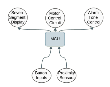
High level structure of project
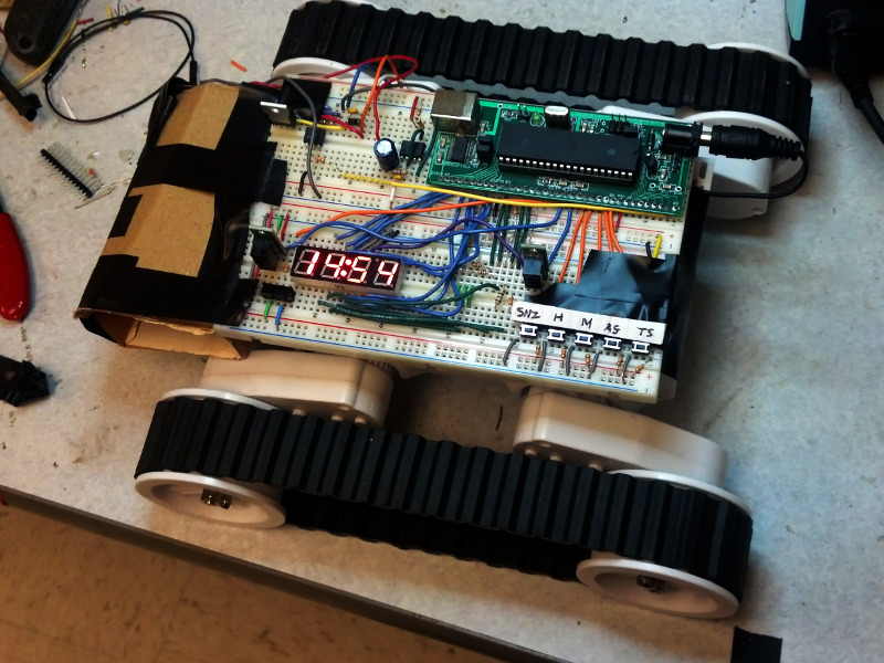
We implemented a prototype for a moving alarm clock which runs away from the user when they try to silence the alarm. It has all the features of a “regular” alarm clock: settable time and alarm, snooze, and alarm on/off. The alarm clock displays the time in 24-hour format on a LED seven-segment display. The whole unit is mounted on a chassis with caterpillar-style wheels driven by two small DC motors. A proximity sensor is mounted near the snooze button which is activated whenever the user’s finger nears the button, causing the clock to move away. It is intended to lure the user out of bed when the alarm sounds. Instead of being able to hit snooze three or four times and sleep in, the user will have to get up and chase the clock to silence it.
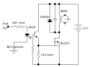
We made use of the motor control circuit from ECE 4760 lab 4. This circuit uses a transistor as a digital switch, and an optoisolator to completely isolate the microcontroller from the motor’s power supply. The microcontroller also gets its power directly from the same battery pack, so we used two large capacitors across the power supply plus a diode in series with the MCU to insulate the microcontroller against any voltage spikes generated by the motor. When we designed the motor control circuit, we also experimented with different motor speeds (changed using the motor supply voltage) to see find the optimum speed for the alarm clock. The figure below is the schematic of the motor control circuit used.
The proximity sensors we used came in a three-pin package. The three connections were VCC, ground, and output. At any time, the sensor outputs a digital high or low depending on whether it senses an object. The sensor’s output was active low. No debouncing or filtering was necessary on its output, which was fed directly into the microcontroller.
The resistors we used to connect the display to the microcontroller are 75 ohms. Without the resistors, the microcontroller will drive too much current through the device, risking destroying the LEDs. We at first tried 100 ohm resistors, but realized these restricted the current too much and made the display too dim. We settled on 75 ohms through a process of trial and error.
We generate the time base using one of the hardware timers on the ATMega microcontroller. An ISR routine is triggered by this timer at 62.5 kHz. (This rate is a remnant of when we were digitally synthesizing the alarm tone in software.) A counter counts ISR routines, and when it reaches 62,500, the current second is incremented. Similarly, when the current second reaches 59, the minute is incremented, and likewise for the hour.
Every time the minute changes, the software compares the current time with the time the alarm is set for. If the two times are equal, and the alarm is set, then it will turn on the alarm tone. When the snooze button is pressed, the alarm is re-set for 9 minutes in the future. In order to remember the original alarm time, the software keeps track of two alarm times: the time actually set by the user, and the “effective” alarm time, which is adjusted every time the user snoozes the alarm.
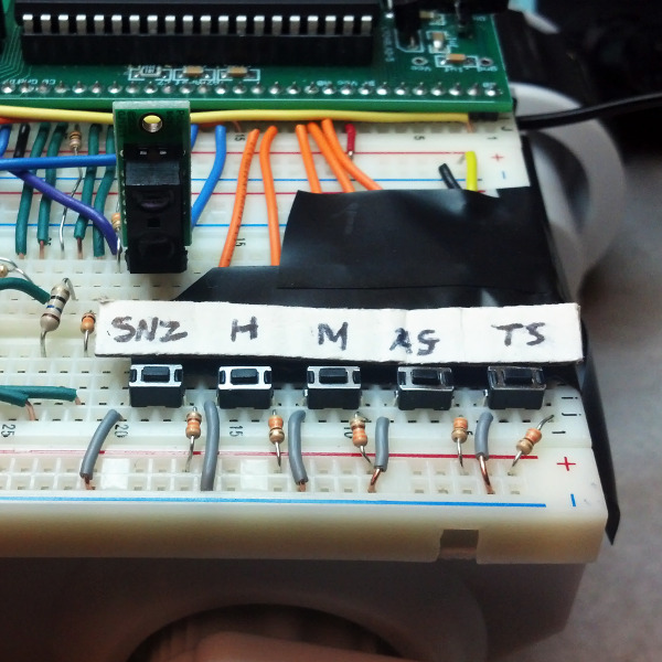
The alarm clock interacts with the user and the outside world through two sensors and several buttons and switches. All of the inputs are active low, and are wired to the pins of Port A on the microcontroller. The main function and entry point to the alarm clock software first performs initializations, and then enters an input-scanning loop. This loop runs as a TRT task. Debouncing is necessary for only two of the inputs: Incr Hour and Incr Min. For these buttons, a debouncing routine is run roughly every 30 milliseconds. Once a definite push is detected, the software takes action based on whether either Time Set or Alarm Set is also depressed at that instant.
| Name | Kind | Function |
| Snooze | SPST Push | If pressed when the alarm tone is playing, silence and reset the alarm 9 minutes into the future. |
| Time Set | SPST Push | When pushed, allows the Incr Hour and Incr Min buttons to advance the clock time. |
| Alarm Set | SPST Push | When pushed, shows the alarm time on the 7-seg and allows the Incr Hour and Incr Min buttons to advance the alarm time. |
| Incr Hour | SPST Push | Advances the clock hour, or the alarm hour, depending on the state of Time Set/Alarm Set. |
| Incr Min | SPST Push | Advances the clock minute, or the alarm minute, depending on the state of Time Set/Alarm Set. |
| Alarm On/Off | SPDT Toggle | Toggles whether the alarm is set, i.e. whether the tone will sound when the clock time and alarm time are the same. |
| Snooze Sensor | Proximity Sensor | Senses whether an object is present near the snooze button, and if so, turns on motion. |
Responsible for keeping track of the current second, minute and hour. It also would call displayTime() to update the seven-segment display. It was also responsible for keeping track of the debounce time and toggling the alarm tone control signal when the alarm was ringing and the colon on the seven segment display every half second.
snooze():Responsible for turning alarm tone off if alarm is currently ringing and updating the new alarm time to 9 minutes into the future. Triggered whenever snooze pushbutton (PIN A.4). is pushed.
turnAlarmOn():Responsible for turning alarm functionality on (currently set alarm time will ring) and turning on alarm on indicator led on seven segment display. Triggered whenever toggle (PIN A.5) is switched to low.
turnAlarmOff():Responsible for turning alarm functionality off (currently set alarm time won’t ring) and turning off alarm on indicator led on seven segment display. Triggered whenever toggle (PIN A.5) is switched to high.
incrMinute():Called whenever debounced increment minute pushbutton press occurs (PIN A.2). Increments current time if time set button is also asserted (PIN A.0) or alarm time if alarm set button is also asserted (PIN A.1). Otherwise no increment is done.
Called whenever debounced increment hour pushbutton press occurs (PIN A.2). Increments current time if time set button is also asserted (PIN A.0) or alarm time if alarm set button is also asserted (PIN A.1). Otherwise no increment is done.
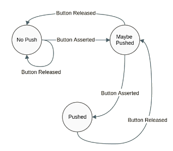
debounce():Debounces increment hour and increment minute buttons through the use of a state machine ever 30 milliseconds. Uses the following state machine:
initialize():Initializes microcontroller ports as inputs and outputs. PORT A is used solely for input from the pushbuttons and proximity sensors. PORT B is used as output for the control signals (alarm tone and motor control). PORTC is used as an output to choose which digit to display in the seven segment display as well as driving the colon and alarm clock led on the seven segment display. PORTD is used solely for output to drive the segments for the seven segment display.
main():Calls initialization functions and creates a TRT task to update the seven segment display. It also polls the inputs.
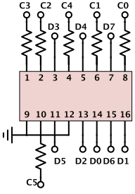
The third major software-based component is continuously driving the seven-segment LED display. This device has four digits, each with its own decimal point, a colon, and an extra indicator dot. It is multiplexed such that it can be controlled by “only” fourteen output pins from the microcontroller: eight to control individual digit segments and the decimal points, four to enable or disable each digit, one to control the colon, and one to control the extra dot. The downside of this multiplexing is that the digits can be active only one at a time (otherwise, they would all be showing the same number).
We wrote a driver for the seven-segment display with an API that we use in the main software. This driver is a modular component: it knows nothing about the alarm clock functionality and could be incorporated directly into a future project using the display for a different purpose. It runs as a TRT task, continuously enabling the first digit only, setting the segment-controlling outputs appropriately, allowing the digit to be visible for 100 ms, and then repeating this for digits two, three, and four. We had to do some experimentation in finding the optimal refresh rate that would eliminate flicker in the seven segment display. We used the upper dot on the display to indicate whether the alarm is on/off and flashed the colon every second.
Used to set the digits to display on the four digit seven segment display
seven_seg_setColon(bool col):Turns on the colon on the display if col=true and off if col=false
seven_toggleColon():Toggles colon on display. If the colon is already displayed, it will be turned off and vice versa.
seven_seg_setUpperDot(bool ud):Turns on the upper dot on the display if ud=true and off if ud=false
seven_seg_init():Initializes the ports used by the microcontroller to drive the seven segment display.
seven_seg_run():TRT task that updates the display using the values set by seven_seg_setDigits(char d3, char d2, char d1, char d0). In every iteration, updates each digit sequentially while waiting in between updates to prevent flicker and incorrect updating.
The weakest aspect of our alarm clock’s performance was the battery life. Our design required that the two sensors and the LED seven-segment display were powered and running continuously. Also, the microcontroller itself draws much more power than would be required of a less full-featured but more specialized chip. Running off the 6xAA battery pack, the alarm clock exhibits degraded functionality after one full night. The sensors are not as responsive, motion is slower, and the alarm tone is quieter and lower in pitch. The time is still displayed brightly and accurately.
The moving alarm clock is easily usable by the general population. The seven-segment display is bright enough to be read in daylight or night, and the alarm tone should be loud enough to wake heavy sleepers but not too loud as to cause pain. However, the unit may not be useful to those with physical disabilities that prevent them from chasing after it. A possible future development could be to have the option of disabling motion, increasing its usefulness for such people. It can also give able-bodied individuals the option to “be lazy” and not be required to chase after it on a day when they can sleep in, for example.
While our alarm clock was very effective in running away, it could be inconvenient and frustrating for sleepier users to constantly run after the clock. One soultion would be to limit the number of times the clock can run away as the objective is to force the user to get out of bed to turn the alarm clock off. Once the clock has moved a few times, the clock will be far enough from most users that additional movement would be redundant. This could also be an option for the user. We could also add obstacle detection for the alarm clock to prevent it from crashing and not being able to move as far.
| Item | Vendor | Unit Price | Quantity | Cost |
| ATMega 1284p microcontroller | ECE 4760 lab | $5.00 | 1 | $5.00 |
| 7-segment display, 4 digit | Sparkfun | $1.95 | 1 | $1.95 |
| Breadboard | ECE 4760 lab | $6.00 | 2 | $12.00 |
| 1.5W 8 Ohm Speaker | Mouser | $4.03 | 1 | $4.03 |
| Pololu Carrier with Sharp GP2Y0D810Z0F Digital Distance Sensor 10cm | Pololu | $6.95 | 2 | $13.90 |
| 555 Timer IC | ECE 4760 lab | $0.00 | 1 | $0.00 |
| BUZ73 Transistor | ECE 4760 lab | $0.00 | 1 | $0.00 |
| 4N35 Optoisolator | ECE 4760 lab | $0.00 | 1 | $0.00 |
| 1N4001 Diode | ECE 4760 lab | $0.00 | 2 | $0.00 |
| AA Batteries (Sony 8-pack) | The Cornell Store | $1.161/2 ea. | 6 | $4.66 |
| Dagu Rover 5 Tracked Chassis | Pololu | $49.95 | 1 | $49.95 |
| Total Cost | $91.49 |