Adding a trace facility requires a modified kernel and settings file. Download:
Cornell University ECE4760
A preemptive kernel
for Atmel Mega1284 microcontrollers
Introduction
It is useful to be able to write several small tasks running on a microcontroller, as if each one were the only program running. For instance, if you were running several communications protocols, it would be nice if each could run without worrying too much about the operation and timing of the other protocols. It is also handy if you have several state machines running at different rates. Obviously, only one task at a time can actually execute on the MCU. To make each task think it owns the whole machine, the state of the task has to be saved while other tasks execute. The swapping process, as well as other functions (e.g. intertask communication) are handled by an real-time kernel. This page describes a very small, fairly fast kernel for the Mega644. While an real-time kernel makes some aspects of programming easier, there are many times that an MCU cannot run an OS and meet requirements for timing or memory use. For instance, if you are doing one or two very fast operations, like generating video, don't use an operating system. (older STK500/Mega644 documentation)
Tiny Real Time (TRT), a real-time kernel
The operating system I will describe, called TinyRealTime (TRT) was written by Dan Henriksson and Anton Cervin (technical report). (See also Resource−Constrained Embedded Control and Computing Systems, Dan Henriksson, 2006) This kernel has several characteristics which make it interesting for ECE4760:
There are several requirements and limitations to apparent task independence on one cpu:
The API supplied with TRT includes core real time routines:
void trtInitKernel(uint16_t idletask_stack) |
Sets up the kernel data structures. The parameter is the desired starck size of the idle task. For a null idle task, a stack size of 80 should be sufficient. |
void trtCreateTask(void (*fun)(void*), |
Identifies a function to the kernel as a thread. The parameters
specify a pointer to the function, the desired stack size, the initial release
time, the initial deadline time, and an abitrary data input
sturcture. The release time and deadline must be updated in each task
whenever trtSleepUntil is called. The task structures are
statically allocated. Be sure to configure MAXNBRTASKS in
the kernel file to be big enough. When created, each task initializes
35 bytes of storage for registers, but stacksize minimum is
around 40 bytes. If any task stack is too small, the system will crash! |
void trtTerminate(void) |
Terminates the running task. |
uint32_t trtCurrentTime(void) |
Get the current global time in timer ticks.
|
void trtSleepUntil(uint32_t release, |
Puts a task to sleep by making it ineligible
to run until the release time. After the release time, it will run when
it has the nearest deadline. Never use this function in an ISR. The (deadline)
- (release time) should be greater than than the execution time
of the thread between trtSleepUntil calls so
that the kernel can meet all the deadlines. If you give a slow task a
release time equal to it's deadline, then it has to execute in zero
time to meet deadline, and nothing else can run until the slow task
completes. Experiment with this
test code by changing the difference in the spoiler task
while watching A.0 on the scope. |
uint32_t trtGetRelease(void) |
Gets the current release time of the running task. |
uint32_t trtGetDeadline(void) |
Gets the current deadline time of the running task. |
void trtCreateSemaphore(uint8_t semnumber, |
Creats a semaphore with identifer semnumber and initial value initval. Be sure to configure MAXNBRSEMAPHORES in the kernel file to be big enough. The identifer number is 1-based, so the first semaphore you define should be numbered 1. |
void trtWait(uint8_t semnumber) |
Causes the running task to wait for the semaphore if it's value is zero, but coutinues execution (and decrements the semaphore) if the value is greater than zero. Never use this function in an ISR. |
void trtSignal(uint8_t semnumber) |
Adds one to the semaphore. If another thread is waiting on the semaphore, and has a nearer deadline, a context switch will occur. You can use this function in an ISR. |
uint8_t trtAccept(uint8_t semnumber) |
Returns the count of the specified semaphore (before it is decremented). If the semaphore has a nonzero value, the value is decremented. Your task must check the return value. This function does not block. You can use this function in an ISR. |
Running TRT: Example 1
Download the following files and put them on one directory.
Configure a
project with test1TRT.c as the only source or header file.
The code assumes that PORTC is connected to LEDs on pins 1,2,3,4 and 7. PORTB pin 0 is connected to a switch (and 300 ohm resistor to ground) and the USB-USART jumpers are mounted. The kernel source code is included below by permission of the authors ( Dan Henriksson and Anton Cervin).
The example contains four tasks:
With 4 tasks running, it takes about 700 cycles to perfrom a context switch by signalling a semaphore (Code to test this). The actual time spent in the scheduler ISR (timer1 compare-match) is 390 cycles, plus 70 cycles to store state, plus 70 cycles to restore state equals 530 cycles to service a timer tick.
Running TRT: Example 2
Download the following files and put them on one directory.
Configure a project with TwoTasksTRT.c as the only source or header file.
The code assumes that PORTC is connected to eight LEDs (and 300 ohm resistors). PORTB is connected to eight switches (and 300 ohm resistors to ground) and the USB-USART jumpers are mounted. The kernel source code is included below by permission of the authors ( Dan Henriksson and Anton Cervin).
The example contains two tasks:
s, c or t followed by a space then a number between 0 and 7. For example s 0 sets LED on. Configuring TRT.
You need to set the maximum number of tasks in your application and the maximum number of semaphores used. The prescalar can be set to any value allowed for Timer1, but the two prescalar defines need to match. You also need to tell the kernel what the crystal clock frequency is and tell the UART what baud rate you want. In the file trtSettings.h you will want to modify:
#define MAXNBRTASKS 4
#define MAXNBRSEMAPHORES 6
#define PRESCALER 1024                     // the actual prescalar value
#define PRESCALEBITS 5                     // the bits to be set in TCCR1b
#define F_CPU 20000000UL                   // crystal frequency in Hz
#define TICKSPERSECOND F_CPU/PRESCALER     //The CRYSTAL frequency/prescalar

/* UART baud rate */
#define UART_BAUD  9600
Each task should be written as a void function with one parameter. See the example code.
The (deadline) - (release time) should be greater
than than the execution time of the thread between trtSleepUntil calls
so that the kernel can meet all the deadlines. If you give a slow task a release
time equal to it's deadline, then it has to execute in zero time to
meet deadline, and nothing else can run until the slow task completes. Experiment
with this test code by changing
the difference in the spoiler task while watching A.0 on the scope.
Do
NOT modify any registers affecting timer1!
If the tick time is critical
for some aspect of your code (e.g. realtime clock), DO NOT USE the TRT timer
tick as a reference. It is not accurate enough.
You can use the soft timers defined below.
Adding Soft Timers
It is convienent to be able to define an arbitrary number of timers. An additional module allows you to define periodic or one-shot times of 0.1 millisecond to several second durations, and to signal a TRT semaphore when the timer completes. The timer API is:
void trtInitTimer(void) |
Initializes timer0 to either 0.1, 1 or 10 mSec tick time as determined by the TIMERTICK macro value. Only 0.1, 1 and 10 MSec are supported. This function also sets up timer structs. The macro value MAXNBRTIMERS must be greater than or equal to the total number of timers you define. This function initializes timer0 and enables the timer0 compare-match ISR. |
void trtSetTimer(uint8_t timer_number, |
Sets a timer denoted by timer_number. The mode can be either PERIODIC or ONESHOT. A semaphore value of zero disables signalling, otherwise a semaphore will be signalled when the timer times-out. This function does not start the timer running. Note that timer_number is one-based. The first timer used should be labeled one. |
void trtStartTimer(uint8_t timer_number) |
Starts a timer. |
void trtStopTimer(uint8_t timer_number) |
Stops a timer. |
void trtDisableTimer(uint8_t timer_number) |
Disables a timer until the next time trtSetTimer is called for that timer. |
uint8_t trtStatusTimer(uint8_t timer_number) |
Returns the status of the timer. Bit zero is run/stop (1/0), bit one is oneshot/periodic (1/0) and bit seven is enable/disable (1/0). |
uint16_t trtNumPeriods(uint8_t timer_number) |
Returns the number of times that the timer has timed-out since it was last set. |
The timer module includes two macros which need to be configured. MAXNBRTIMERS and TIMERTICK must be set by the user. The code assumes a 16 MHz crystal driving the MCU. Modification to trtInitTimer will be necessary for different clock frequencies. An example program sets up three timers and uses them to control some tasks. Note that this module uses timer0 for interval timing. All the real work happens in the compare-match ISR. If you use this module, do not change any timer0 registers. The program assumes that PORTC pins 1,2,3 and 4 are connected to four LEDs (and 300 ohm resistors).
Adding a Mutex
A mutex is a binary semaphore with states LOCKED and UNLOCKED. A task can gain control of a resource by locking a mutex. The same task must unlock the mutex (unlike a semaphore which can be signaled by any task). A basic mutex facility was built on top of the existing TRT semaphores. Since a mutex is a special semaphore (and uses the semaphore signaling mechanism) , each mutex must be numbered not to conflict with another semaphore. The mutex API is:
void trtInitMutex(void) |
Initializes a data structure with size MAXNBRSEMAPHORES. and sets the state of each entry to UNLOCKED and the owner to NONE. |
void trtCreateMutex(uint8_t mutex_number) |
Creats a mutex with identifer mutex_number, initial value UNLOCKED and owner to NONE. Since a mutex is a special case of a semaphore, be sure to configure MAXNBRSEMAPHORES in the kernel file to be big enough to hold all semaphores+mutexes. The semaphore identifer number is 1-based. |
void trtLockMutex(uint8_t mutex_number) |
Locks the mutex and sets the owner to the current task. |
void trtUnlockMutex(uint8_t mutex_number) |
Unlocks the mutex and sets the owner to NONE. |
uint8_t trtQueryMutex(uint8_t mutex_number) |
Returns the status: LOCKED or UNLOCKED. |
uint8_t trtOwnerMutex(uint8_t mutex_number) |
Returns a binary true if the current task is the owner. |
The mutex module and an example show how to use a mutex to control LEDs flashing. LEDs are on PORTC, and switches on PORTB.
Adding a trace facility
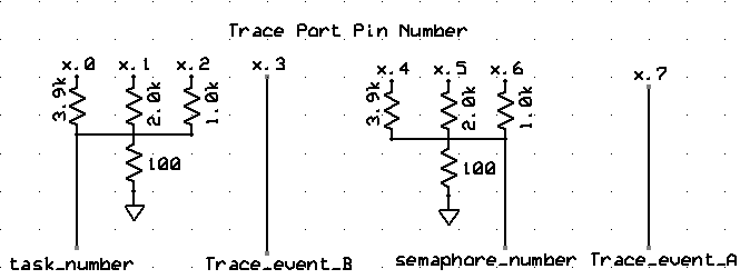
A realtime trace facility was added to TRT to enable following which tasks are executing and which semaphores are signaled. There are also to user defined events available. The trace facility uses one port of the MCU to dump data to an oscilloscope. A simple 3-bit DAC is used to convert task number and semaphore number to two separate voltages for display. Each task number adds about 125 mV to the output, so that when task 2, for example, is executing the voltage output is 250 mV. The semaphore number is specified when you initialize a semaphore. The task number starts at zero for the null task, then each task has a number defined by the order in which the tasks were created. Either of the events may be used as a scope trigger or to display. The connections are shown below.
Adding a trace facility requires a modified kernel and settings file. Download:
The trace port is chosen in trtSettings.h. Defining a trace port turns on the trace facility. Commenting out the definition disables trace. You must also define the data direction register for the trace port as shown below.
// trace options
// use one port for realtime trace
// IF TRACE_PORT is undefined, then trace is turned off
#define TRACE_PORT PORTA
#define TRACE_DDR  DDRA
You can also choose to have a semaphore number held for only a few microceconds (INSTANT_SEM) or to be held through a context switch. This means that semaphore signals which force a context switch will result in longer lasting waveforms and that you can tell when a context switch occurs as a result of a signal. Comment out one of:
//#define EXTEND_SEM
  #define INSTANT_SEM
There are four macros which can be inserted anywhere in your code. If you disable the trace facility you must remove the macros you inserted in your code.
TRACE_EVENT_A_ON |
Turns on bit 7 of the trace port |
TRACE_EVENT_A_OFF |
Turns off bit 7 of the trace port |
TRACE_EVENT_B_ON |
Turns on bit 3 of the trace port |
TRACE_EVENT_B_OFF |
Turns off bit 3 of the trace port |
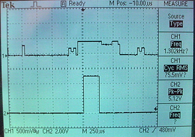
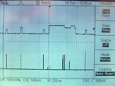
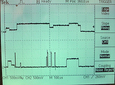
Three images show typical event sequences. The first image shows four tasks on the upper trace and trace event A on the lower trace. As can be seen in the example code, trace event A is turned on just before an fprintf in task 4 and turned off just after. The second image shows four tasks on the upper trace and seven semaphores on the lower trace. The number 1 semaphore in the middle of the screen is triggered by a character from the UART. The number 2 semaphore just to the right is the signal that the UART string is complete (user pressed enter). The long period spent in task 4 is the same as in the first image. Near the end of the long duration task 4, semaphore 5 is signaled which causes task 3 to execute, then bounce back to task 4 when semaphore 4 is signaled. The third image is similar, but with EXTEND_SEM turned on to show when context switches occure as a result of semaphore signals.
Adding a system dump facility
A dump facility was added to TRT to enable debugging of timing errors and stack overflows. A set of low level routines read out the status of any task, semaphore or mutex. A set of printing routines uses the low level routines to print status information to the serial port. The task number parameter in the table below refers to the lexical order in which tasks are created in the program being tested. The first user task is labeled 1.
uint8_t trtTaskState(char tsk) |
Returns the state of a task. 0=terminated; 1=readyQ; 2=timerQ; 3=wait Sem 1; 4=wait Sem 2; etc |
uint16_t trtTaskStack(char tsk) |
Returns the stack pointer of a task. |
uint16_t trtTaskStackBottom(char tsk) |
Returns the stack minimum address of a task. |
uint32_t trtTaskRelease(char tsk) |
Returns the release time of a task in system ticks. |
uint32_t trtTaskDeadline(char tsk) |
Returns the deadline time of a taskin system ticks. |
uint16_t trtTaskStackFreeMin(char tsk) |
Computes and returns the minimum space left on the task stack since the task was defined. If this value reaches zero for any task, the system crashes! When created, each task initializes 35 bytes of storage for registers. |
uint8_t trtSemValue(uint8_t sem) |
Returns the value of a semaphore. |
uint8_t trtMutexOwner(uint8_t mut) |
Returns the owner of a mutex. |
uint8_t trtMutexState(uint8_t mut) |
Returns the state (locked/unlocked) of a mutex. |
void trtTaskDump(char tsk, char freeze_timers) |
If tsk is zero, prints all task information. If tsk is not zero, prints only the info for that task number.The task number, state, release time (relative to current system time), deadline time (relative to current system time), current free stack space and minimum free task space are printed. Freeze_timers can take the values FREEZE_TIMER and RUN_TIMER. Freezing the timers stops them for the duration of the print operation. This routine can use as much as 90 bytes of stack space for the calling task! |
void trtSemDump(char sem, char freeze_timers) |
If sem is zero, prints all semaphore information. If sem is not zero, prints only the info for that semaphore number. The semaphore number and value are printed. Freeze_timers can take the values FREEZE_TIMER and RUN_TIMER. Freezing the timers stops them for the duration of the print operation. This routine can use as much as 90 bytes of stack space for the calling task! |
void trtMutexDump(char mut, char freeze_timers) |
If mut is zero, prints all mutex information. If mut is not zero, prints only the info for that mutex number. The mutex number. owner and state are printed. Freeze_timers can take the values FREEZE_TIMER and RUN_TIMER. Freezing the timers stops them for the duration of the print operation. This routine can use as much as 90 bytes of stack space for the calling task! |
# state     relT   deadT stkfree stkfreeMin
1    2     1133     1133     8     8
2    1      -12      -12   106    19
3    2     2462     2462    87     9
# value
5    1
# owner UNLOCK
3    0     1
Adding a dump facility requires a modified kernel and settings file. The following includes both the trace and dump facilities. Download:
Simple command shell:
A simple command shell was written as a task which can be signaled (entered) from any other task and which supplies a command-line interface to task values, semaphore values, memory contents, and i/o registers. The example assumes at buttons are connected to PINB, LEDs to PORTC, and the D0 and D1 to the uart. The trtkernel_1284_trace_dump.c kernel and trtQuery.c are required as above. Pushing button 2 or 3 will enter the shell with different IDs.
Shell commands:
g |
Exit command shell and run other tasks |
signal_shell(char ID) |
When used in other tasks, this macro enters the command shell
and prints the specified ID. Timers are frozen and interrupts disabled. Example: signal_shell(4) |
x |
Forces a RESET of the MCU and trashes the state of your program. |
i ioregAddress |
Read an i/o register. The register address is entered in
hexadecimal, with space delimiters. The address used must be the value
in parenthesis in the table (see data sheet in the range 0x20 to 0xff
). The result displayed in in
hex. Example: i 23Reads the state of the pushbuttons attached to PINB. |
I ioregAddress iodata |
Write to an i/o register. The register address and data
are entered in hexadecimal , with space delimiters. The address used
must be the value in parenthesis in the table (see data sheet in the
range 0x20 to 0xff ). |
t tasknumber |
Gets information about a task. The first
task has index 1.
t 4 returns information on task 4.Example: t 0 returns information on all tasks. |
s semaphorenumber |
Gets information about a semaphore. The first semaphore
has index 1. s 4 returns information on semaphore 4.Example: s 0 returns information on all semaphores |
m memAddress |
Reads SRAM. The memory address is entered in hexadecimal,
with space delimiters. Addresses 0x00-0x1f are the cpu data registers,
0x20-0xff are i/o registers, and 0x100-0x10ff is actual RAM. The result
displayed in in hex. You can find out where global variables are stored
by opening the .map file and searching for the word common three times.Example: m 1fReads cpu register 31. |
M memAddress data |
Write to an SRAM address. The memory address and data are entered in
hexadecimal , with space delimiters. Addresses 0x00-0x1f are
the cpu data registers, 0x20-0xff are i/o registers, and 0x100-0x10ff is
actual RAM. You
can find out where global variables are stored by opening the .map file
and searching for the word common three times.Example: I 28 f0Turns on LEDs 0 to 3 attached to PORTC. |
Copyright Cornell University October 18, 2013