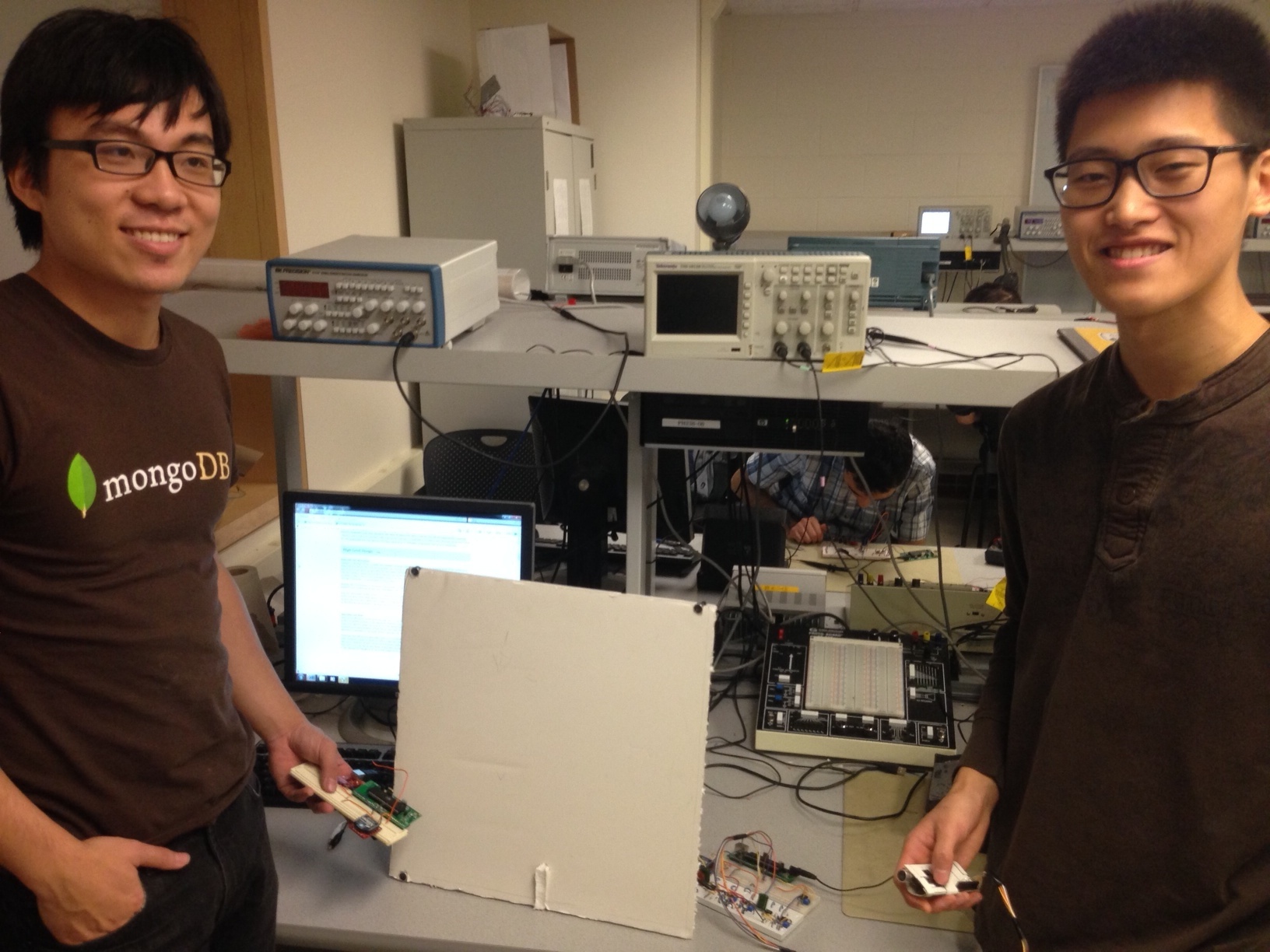
Qichao,Chaoping and the Air Mouse
A Simple Demonstration
Introduction top
"A wireless mouse unit that requires no flat surface by using ultrasonic positioning."
For our ECE 4760 final project,we have designed a surface-less mouse interface using ultrasonic transmission as our final project in this class. The idea is to have a ultrasonic transmitter as a mouse, which represents the mouse’s position in space, with the left, right clicks functionsaccomplished using touch sensors.The separate components to this project include the hardware-generated signal input and the interface to a personal computer. We use a sonar system to position the mouse, and use touch sensors to trigger clicks. There arethree ultrasonic receivers attached to three corners of a board simulating the computer screen(upper-left, upper-right and lower-left corner respectively).Ultrasound travels at roughly 340m/s, and based on the delay of the reception, we can find the distance between the transmitter and receiver, and handle the position calculation with respect to the screen.We used two MCUs, one to generate the data representing the mouse coordinates and clicks activities, the other to import the data to the PC.Two MCUs communicate wirelessly. There is also a software interface with a personal computer to deal with transmitted data through serial port of the PC. We implement the USB generic HID class using java to translate serial inputs into mouse commands.
High Level Design top
Rationale and Motivation
Imagine a situation where a public presentation is given and the presenter has to stand in front of the audience to demonstrate his/her idea. All the presenter can do now is going through the powerpoint slides in which case, information must all be incoporated into the slides. What if the presenter wants to show more information? He/she has two options: going back to the computer and do the operation him/herself or ask an assistant to perform the operation. This is where our inspiration comes from and eventually leads to our solution, a 3-D ultrasonic mouse that can give presenters more freedom of presenting.
Despite the convenience it can bring to presenters, it can also benefit ordinary PC users who do not want to be limited to the traditional mouse and compatible surface.
bsp;The motivation of this project is to develop a mouse that correlates the mouse position to the position of user's hand. We have found that groups of previous years have developed similar projects such as 3D painter or 3D mouse. However they either used relative coordinates or only limit the mouse use to certain applications. Our goal is to develop the most intuitive absolute 3D mouse that could control the cursor directly.
Algorithm and Math
With three ultrasonic sound recievers and one sound transmitter, we want to be able to detect the current location of the transmitter based on the distances between the trasmitter andeach of the receivers. The sound speed is known as 340m/s, which we note as Vs. The timeduration of transmission of the sound wave could be recorded by a synchronized real-timetimer of both MCUs. We note the time as ti (i= a,b,c), then the distance between the ultrasonic transmitter P and each of the recievers A,B, C could be noted as Ra, Rb, Rc, where Ri = Vs / ti (i = a, b, c)
However, the UID device generally reads in a coordinate pair values as (x,y). A simple conversion between Ri values and coordinate values is given as below: Suppose point P is the Ultrasonic sound transmitter;A,B,C represent four ultrosonic receivers at each corner of rectangular laptop ABCD. The projection of P on plan ABCD is O,the projection line of Rc is CO. Ra, Rb, Rc are three measurable distances.Taking C as theorigin, we need to find the value of x and y. We denote the length of AC as a and length of CD as b.

Coordinates Calculation Illustration.
The following equations could be used :
x^2 + (a-y)^2 + I^2 = ra ^2 (1)
x^2 + y^2 + I^2 = rb ^2 (2)
(b-x)^2 +(a-y) ^2 + I^2 = rc ^2 (3)
With equation (1), (2) and (3) we could solve for x, y and I. We note it as ABC, where ABC.x and ABC.y are solved based on receivers A,B,C.
ABC.x = (ra^2 -rc^2) / (2b)
ABC.y =(rb^2-ra^2) / (2a)
In our desgin,we labled our sensors 0,1 ,2 as a,b,c and defined d0 as ra, d1 as rb and d2 as rc.
Desgin Logic
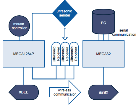
A logic diagram of the desgin
There are two main components of our design: the base station unit and the mouse unit. The mouse unit contains the mouse controller, a mega1284P microcontroller, an ultrasonic sound transmitter, three ultrasonic sound receivers and an XBEE wireless transceiver. The base station contains a mega32 microcontroller and an XBEE wireless transceiver.It is connected to PC using a USB cable. Users input their commands using the mouse controller, the raw distance data will be generated in the mouse unit within the mega1284P microcontroller for it to output the x and y coordinate data. The microcontroller also handles the ISR generated by button click actions. The mouse unit finally encodes the data into packets and the data is then transmitted to the base station unit using XBEE radio transceiver. When the base station receives the data, it encodes and transmit the data to PC through serial connection. The serial data is read and decoded by java application and utilized for the java HID class. A diagram demonstrating the logical structure is shown as above.
Hardware and Software Tradeoffs
Teensy2.0 ++
Inspired by the Glove Mouse project designed by Adam Shih and Hyodong Lee of Fall2012, our first design idea was based on the usage of an extra board teensy 2.0++. It has AT90USB1286 microcontroller and can work as an HID device. We implemented a USART receive complete interrupt service routine so that upon arrival of each data packet , we can read in each data byte and decode their information. We achieved success in transmitting data using USART channel. However, two problems became the reasons that we discarded this design approach. First, teensy simulates a relative mouse. Our three sensors decide an absolute mouse position so that extra calculation needed to be done to get a relative mouse position change. That way, extra errors would be introduced through the calculation and the poor performance of the mouse proved that teensy is a bad choice for our mouse implementation. Second, we encountered a problem of unstable data transmission. Bad data can be read every now and then which required us to use several synchronization bits as headers of our transmitted packet. This led to a certain amount of data loss which caused a significant delay and lack of accuracy of the mouse.
JAVA.awt.ROBOT
Instead we decided to use java to read in the serial data and move the mouse using the java.awt.robot class which provides neat functions that could implement an absolute mouse and perform mouse click actions. More details about this will be introducted in the software section. In a word, to better serve the purpose of devloping a mouse using absolute coordinate bases, we chose java instead of an additional board to finish the task.
Standards
Relevant Patents and Copyrights
Hardware top
Overview
The bulk of the hardware of this project revolves around turning the ultrasonic receivers’ raw voltage swings into digital data that our microcontroller can comprehend. Because the receivers output relatively weak and noisy signals when they receive a 40 kHz signal from the transmitter, we needed to amplify, filter, and then convert the signal into a digital input. We found that putting a constraint in a distance of no larger than two meters would allow us to directly drive the transmitter with a output from the MCU and still get very good response from the receivers, greatly simplifying our hardware for the transmitter circuit. A number of button switches were needed to perform clicking events and state changes. The XBee units and the serial-to-USB breakout boards are capable of communicating serial data directly, requiring no intermediate hardware manipulation.
Ultrasonic Transmit and Receive
Mouse unit board
The Ultrasonic transmitter receives a 40 kHz square wave generated by a PWM output from the Atmega 1284. The transmitter is rated to accept rms voltages up to 30V, far above the range of 0-5V that we feed to it.

Ultrasonic transmitter input

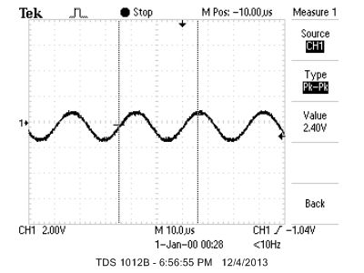
Ultrasonic receiver raw output
When the transmitter is tuned to emit 40kHz signal, the receiver produces a sine wave between 20 and 100 millivolts peak-to-peak. This signal is first passed to a 100x active amplifier tuned at 40 kHz frequency. The non-inverting input to the op-amp is connected to one half of the supply voltage in order to provide a reference for the input voltage’s amplification. As a result, the output has a DC offset voltage at half of the op-amp’s supply voltage.
Ultrasonic receiver amplified output
In the next stage, a passive high pass filter with a cut-off frequency at 80 Hz produces a wave with no DC offset.
Ultrasonic receiver high-pass filtered output
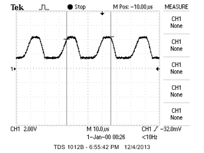
In order to have only one signal change every time the receiver receives a pulse, a peak detector is used to to maintain a high signal throughout each pulse. A diode allows current to pass through only one way, and a capacitor and a resistor forming a time constant of 2 millisecond, far longer than the 40 kHz signal’s period of 25 microsecond, keep the signal essentially flat at the peak value once it is detected.
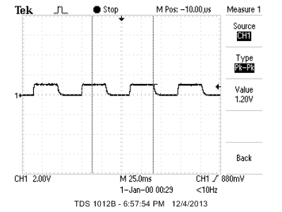
Ultrasonic receiver peak-followed output
At this stage the signal is still analog and may be ambiguous and cause problems if used as an input to the MCU. The LM311P is a very fast comparator that can suit our needs. We experimented with the reference voltage with trimpots and set it at between 50 and 100 millivolt for the three receiver units. The output is now a purely digital 0 to 5 volt signal, which is used to trigger external interrupts in the Atmega 1284 chip.
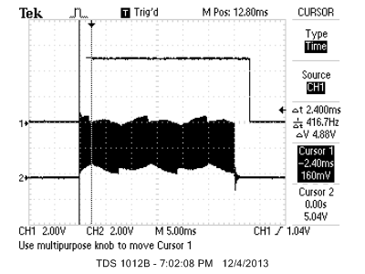
Ultrasonic receiver circuit output compared with transmitter signal. Notice the time delay
Button Push
The lab supply push buttons simply connect and short its two terminals once pushed. We connected one end to ground, and the other in series with a 330 Ohm resistor to an input port on the 1284 chip. When the chip internal pull-up resistor at the corresponding pin is enabled, pressing the button would set that pin to ground voltage, and releasing would set it to the supply voltage.
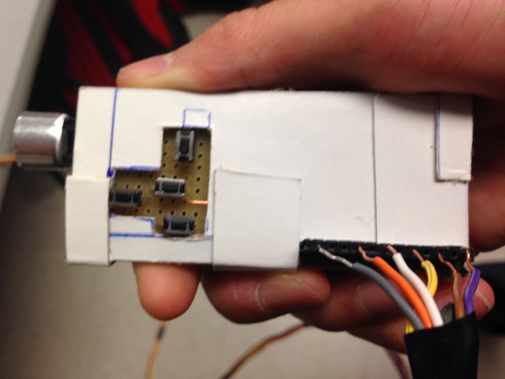
Mouse remote with ultrasonic transmitter and buttons
XBee and Serial-USB Breakout Boards
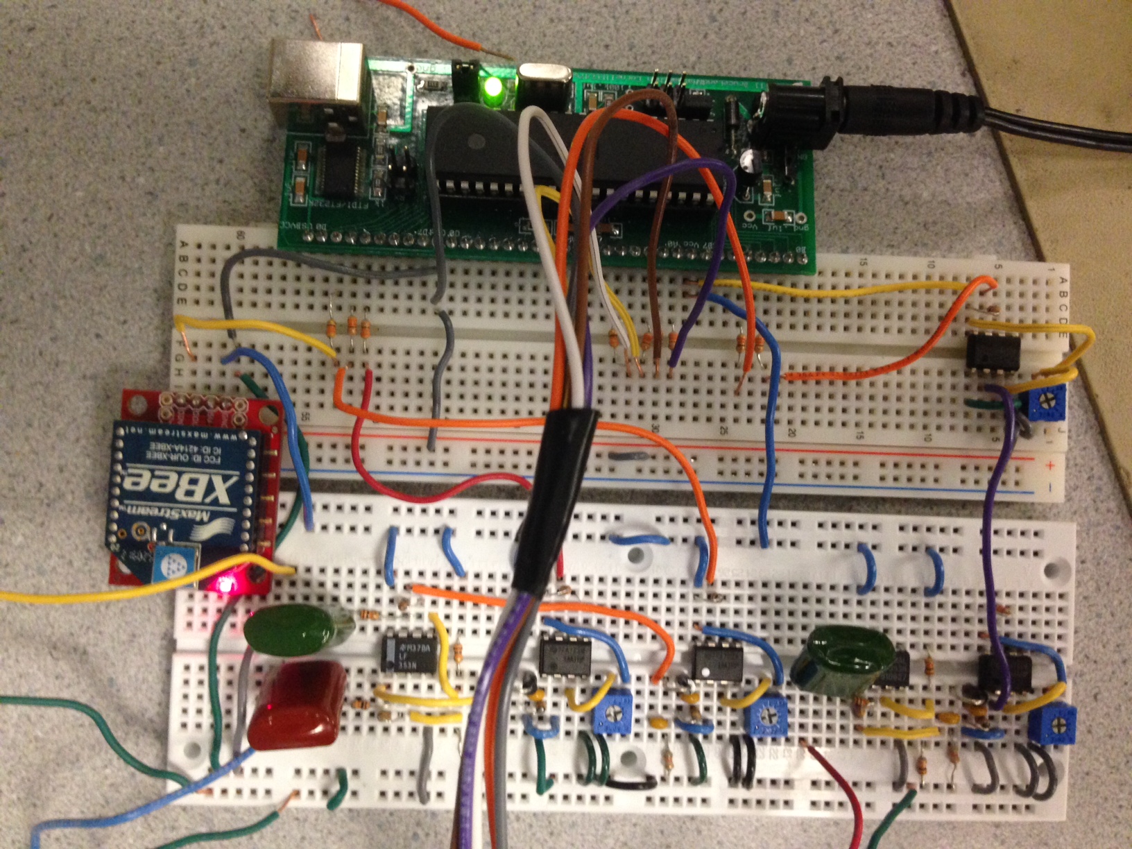
The Atmega 1284 and 32, the XBee, and the serial-USB breakout boards all have ports that output serial signal and ones that read serial input. We only need to use wires to connect the serial transmit port of one device to the serial receive port of another to enable communication between them.
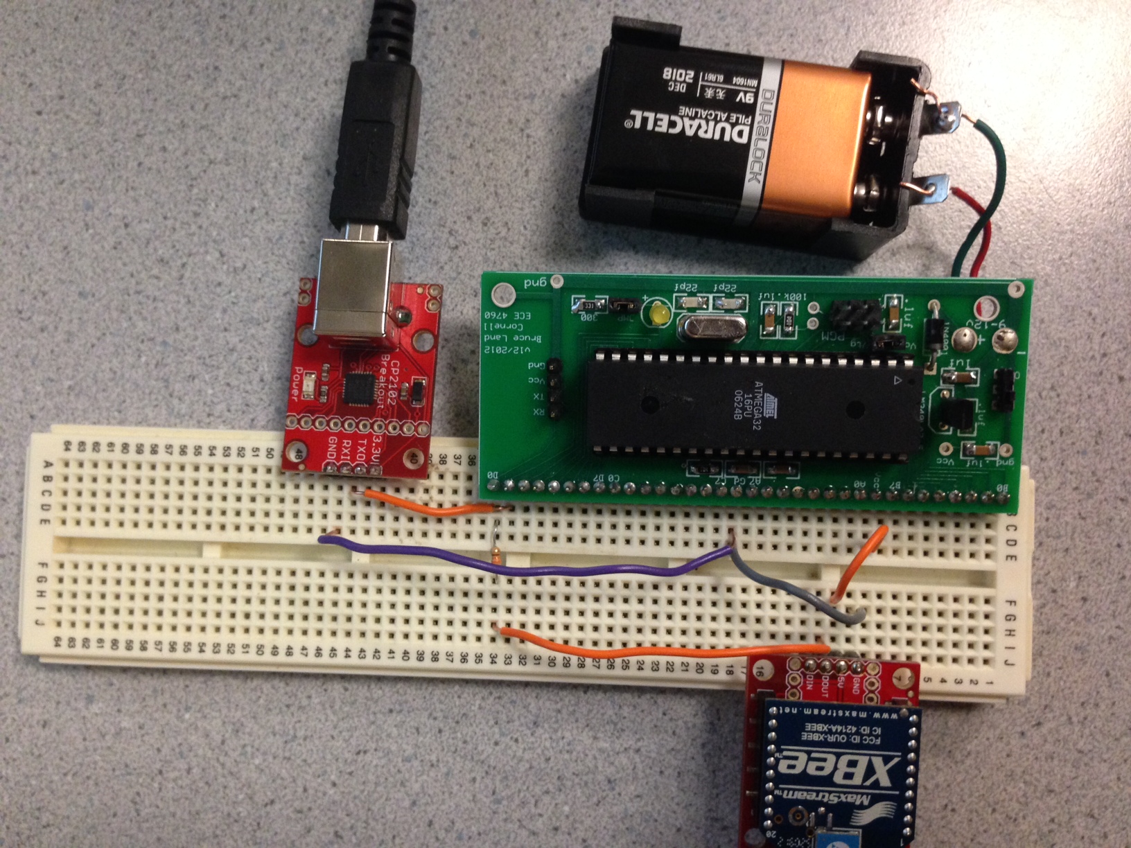
Atmega 32, XBee, and serial-USB hardwares
Ultrasonic Sensor Frame
In order for the ultrasonic sensors to produce differentiable delay times and make triangulation calculations possible, they need to be at some distance apart from each other. Our original idea was to mount the sensors on a frame that would fit onto a computer screen. However, that proved to be time consuming to set up, and would require a very flexible and complex frame in order for the project to work on screens of different sizes. We decided to mount the sensors on a frame instead. A square board was cut out from a poster board, and the sensors were hot-glued into wedges at the top-left, top-right, and bottom left corners of the board. To make the frame stand upright, we cut out a piece of the bottom center and wedged a rectangular piece of foam in it, forming a T shape at the base so the frame would not fall. The sensor legs are plugged into pin headers, which are soldered onto wires that lead to the rest of the circuit. This way in case of a failure of the sensors, we can easily swap them out.
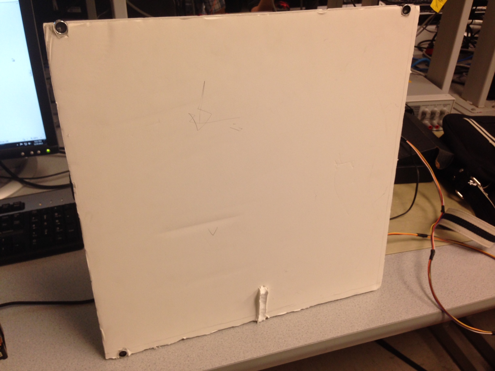
Ultrasonic sensors on poster board frame
Software top
Overview
The software is divided into three code blocks: ultrasonic coordinate control, radio and PC communication, and mouse control. The first two are implemented in c on the two MCU’s, and mouse control is written in java and runs on the PC. In the following paragraphs software for each device is discussed in detail.
Data Format
We use a packet size of 9 bytes to contain the information of mouse position, mouse click and mode change as shown in the graph.

Packet Format
Byte 1 and 2
Byte 1 and 2 represent x and y coordinates respectively. Byte 1 contains values ranging from 0 to 180 and 2 contains values from 0 to 170. The values 180 and 170 are decided based on the timer count measurement of the actual width and height of the board we used to simulate the screen of a computer.
Byte 3
Byte 3 contains information about mouse click. It can be 0,1 or 2, representing no click, right click and left click action respectively.
Byte 4
Byte 4 is the mode change byte. A value of 0 means no changing of mode. A value of 1 means a change of operation mode happens.
Byte SYNC
The SYNC byte takes the value of 0xAA, it marks the start of each transmitted packet. We used polling in our Mega32 microcontroller to read each transmitted packet and therefore needs a synchronization byte to start data reading from the correct location. The reason we chose polling as our data reading method is because the USART receive interrupt service routine is not functioning as we expected.
Atmega 1284 (Mouse Unit)
The mouse unit is responsible for calculating the position of the ultrasonic transmitter in relation to a coordinate system defined by the distance between the ultrasonic receivers, as well as registering events like mouse clicks and mode changes.
Ultrasound Transmit
It uses timer 0’s compare match mode to produce a 40 kHz signal to port B2. Every 40 milliseconds this signal is toggled so that 1) the receiver circuits can have time to react and produce square waves, and 2) we can use the same cycle for debouncing button pushes. Furthermore, every 40 milliseconds a check is performed to determine whether the enable button is held down. If not, the transmit port would be turned off, and the MCU would not perform any other tasks, instead sleeps for 40 milliseconds, when it performs the same check again. This is to ensure that the user can keep the cursor at a fixed location when they hope to move their hand freely.
Counting Delay
Timer 2 is used to count the delay time between sending and receiving ultrasonic pulses. It has a prescaler of 128, given our 16 MHz clock and the speed of sound at 340 m/s, each count would represent 2.72 millimeters, which is small enough to smoothly detect changes in hand motion, but large enough to avoid significant signal noise caused by slight trembling of the hand. When a receiver circuit triggers an external interrupt, timer 2’s count is recorded and stored into a variable specific to the receiver . Before the MCU sends out a 40 kHz pulse, timer 2’s count is set to 0, and immediately starts counting up, until it overflows at 256, in which case an overflow interrupt records the event and increments a variable, giving it a theoretical max count of 65535. If more than once sensor are at a distance from the transmitter within 2.72 millimeters, only the one external interrupt will register. This is handled by only calculating the coordinates from the delay variables at the end of each 40 ms cycle, when the missed delays would remain at 0. In reality this situation is rare and are almost always filtered out by the median filter. In order to smooth the signal and filter out outliers, we implemented a median filter followed by a mean filter, both with the size of 5 values.
Calculating Position
Using the method discussed in the first section of this report, we are able to calculate the position of the transmitter. Because distance is just a scaler operation on the delay counts, we simply use the delay counts as our unit for calculation. We calibrated the width and height of our frame by placing the transmitter at the same distances as between the receivers. The resulting x y coordinates undergo another layer of median filtering, this time the filter size being 3, to ensure that we have a stable set of data for transmission to the PC mouse control.
Debouncing
With the exception of the enable button, which is checked every 40 ms, all the buttons need to be debounced because each press by the user should represent one event. . Again, the state machine updates once every 40 ms, which makes the event almost instantaneous to human perception. The state machine used to achieve this is illustrated below.
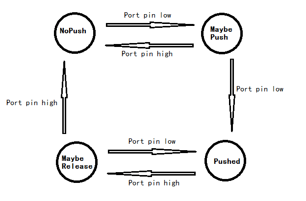
Button push debounce state machine
Function Listing
Button push debounce state machine
Only enter at rising edges. Check if a specific receiver has already received a signal. If not, set flag to indicate that it has received signal during this 40 ms cycle (so that if noise causes the comparator output to oscillate after the first rising edge, it would be ignored) and record timer 2’s count to a volatile variable.
comp
Comparison function to enable the use of qsort. Provides comparison between uint16_t types.
avg_array
Calculates the average value of all values in an array.
USART_init
Initializes uart 0 by setting the baud rate and enabling transmit.
USART_txByte
Transmits a byte of data through uart 0’s transmission port. Polls and waits until uart is ready to transmit data, then puts the data byte into UDR0.
tx_packet
Transmits four bytes of input data. Every packet begins with a synchronization byte of a known value. Total number of byte transmitted is 5.
UltraTransmit
This real time task executes every 40 ms and does all of the distance calculation and button debouncing, followed by sending five bytes of serial data to the XBee radio. Every cycle it toggles the timer 0 compare match isr, essentially turning it on and off. It first checks if the enable button is pushed. If not, turn off the 40 kHz output port and go straight to the button push detection code. Otherwise, turn it on and check timer 0 compare match isr’s state. If timer 0 CTC is turned off, we turn it on, zero timer 2’s count and the flags that indicate whether signal has been received in this round. If timer 0 compare match isr is already turned on, then we turn it off, filter the delay counts and do the position calculation. If either x y position falls outside of the bounds, set it to the boundary value. Before entering the button push state machine, the function checks if either mouse click event needs to be sent to the serial port. Because all the information, position, mouse click, and mode change, are sent at the very end, this avoids repeated clicking commands being sent when user holds down a click button. However, the mode change variable does not need such mechanism because once toggled, the function can keep sending the same mode value to indicate that the mode has not changed.
main
The start of the main function initializes the ports, turn on pull-up resistors, set timers, set up the external interrupts. Lastly tiny real time is initialized, and the bulk of the program, the UltraTransmitt function is created, and puts the CPU to sleep to save power when no task is running.
Atmega 32 (Base Station Unit)
The code running in the atmega 32 is responsible for receiving the positioning and button push information from the mouse unit, and sending it via our serial-USB board to the PC. It polls its only uart port’s receive complete bit and sends the data to PC with a little formatting.
Function Listing
my_uart_getchar
A simple function to receive a byte from the serial receive port by polling the receive complete bit and returning the byte from the buffer.
main
The main function initializes the uart, enabling communication with the PC using Joerg Wunsch’s uart code. We only need the MCU to transmit serial data to the PC, and receiving of data is handled by our own getchar function. Main then enters a forever while loop to poll the first byte that it receives, if it matches the synchronization byte, read on to extract the position and button push data. After that, it formats those four numbers in a sequence separated by four capitalized letters represented as characters, and sends them to the PC in the form of decimal numbers.
Communicator.java
We used Java to read in transmitted data directly from the USB. Java has a class java.awt.Robot to control the mouse position and mouse click on an absolute scale which fits well with the absolute coordinates transmitted by the Mega32 base station microcontroller.
Set Up
We used Java to read in transmitted data directly from the USB. Java has a class java.awt.Robot to control the mouse position and mouse click on an absolute scale which fits well with the absolute coordinates transmitted by the Mega32 base station microcontroller.
Function listing
connect
This function establishes the connection with the serial port. It opens a certain serial port(By name) and creates a transmission channel with defined baud rate and data format. Here, in consistent with the received data, we set the baud rate to be 9600 and packet format as a packet with 8 data bits, 1 stop bits and non-parity bits. Then, in order to run the program real-time, we start a new thread executing the reading data function.ble set of data for transmission to the PC mouse control.
list
This function lists all the available ports of the PC.
Run
This function reads in the data. It has one byte for buffer, which is the size of each data packet we send. It will identify the format of the data as" XAXBXCXD" and read in the values for A,B,C,D which corresponds to x coordinate, y-coordinate, left/right click, and mode. Mouse moves to the new position x,y for each data packet. The screen of lab comptuer has an approximate scale of 1500*1000(width* height) based on java robot standard. The origin of the coordinates is the upper left corner..
Results top
Speed of Execution
Our mouse responds reasonably fast to user's action in general. It has a noticeable delay of a few tenths of a second. The bulk of the delay is due to the time constant of our running average filter: 5 elements, multiplied by 40ms for each new data point, causes 200ms delay. Further delay is caused by time used during data transmission between two MCUs and XBEE, two XBEEs, and base station MCU and the PC and base station. 9600 baud rate corresponds to around 0.1ms per byte, and we use that rate for all our serial communication. It also takes time for java to read in and process the data from the PC serial port.
Accuracy
Our device achieved a fairly good accuracy. The Full-screen Mode has a relatively low definition compared to the Regional Mode due to our design purpose. For the full-screen mode, the minimum x and y increments are 8 pixels and 6 pixels; for the regional mode, the minimum x and y increment are both 1 pixel. The transition between two modes also function as expected, there is a small position shift when changing the mode from "Full-screen mode" to "Regional Mode" , it happens due to imperfect matchup between our calculated coordinate system and java robot coordinate system. The mouse click function allows both single clicking and rapid multiple clicking. Theoretically loss of accuracy can happen during the data transmission process where several data packet can be dropped, however, the chance is low, and the next data point arrives in 40 ms.
Safety
Safety is an important factor we consider through our design.One of the reasons that we choose the ultrasonic wave with frequency around 40kHZ is it is well above the hearing range of human beings. However, it is noticeable that some animals such as dogs and cats, can hear sound of this frequency. Therefore, our mouse is not recommended for use when there are cats or dogs present because it will likely cause distribution. The power voltage of the mouse controller is 3.3 V which does no harm to human beings. In addition, we have built a case for the mouse controller component to avoid direct contact between users and any electronic components such as wires, power sources.
Usability
Our mouse is user-friendly and looks like a mini remote controller. The four buttons on the mouse controls three functions: mouse clicks, mode change, and mouse enabling. Users need to hold down the enabling button for the mouse to move around , otherwise it will stay still. Our mouse is easy to use due to the fact that user can control the mouse freely based on the position of their hands which holds the controller, it can go from one position to another smoothly or jump directly from position A to position B. It is intuitive and requires no additional skills. The wire length linking the mouse unit board and remote of our prototype is about 1.5 meters. The effective indoor range of our XBEE wireless transceiver is around 30m.
Conclusions top
Results vs. Expectations
Our device functioned well, but not as fast or responsive as we had hoped. We realized half way through the project that given the relatively inexpensive parts, limited time, and the frequent occurence of junk data from the ultrasonic receivers, a high-precision device as we expected during the project design phase might not be possible. For mouse movement to appear instantaneous to a human, the delay can be 50ms at max. Our device at the stage that we demonstrated in, was simply not fast enough for comfortable use.
Conformance to Standards
The series 1 XBee operates within the ISM 2.4GHz frequency band, which is allowed by the FCC for unlicensed communication. Its transmitt power output is rated at 1mW(0 dBm), well under the FCC regulated 30 dBm maximum.
Intellectual Property Considerations
The uart.c code that enables our atmega 32 to send data to a PC COM port is written by Joerg Wunsch, who licensed the code as a beer ware. We thought it was well worth it and will buy him a beer in return if we ever meet. All code related to tiny real time were developed by Dan Henriksson, Anton Cervin and modified by Professor Bruce Land. No patent was violated.
Ethical Considerations
We completed the project under the guidance of and compliance with the IEEE Code of Ethics. We strove to never put others’ and our won safety in jeopardy throughout the duration of the project. All results we present in this report were obtained with honest effort and represent the true performance of our system to our best knowledge. The project would not have been successful without the valuable advice and help from many classmates, TA’s, and Professor Bruce Land. We hoped to reciprocate the support we received, and responded with honest opinions and suggestions whenever our peers needed our assistance.
Legal Considerations
The series 1 XBee radios we used in our prototype operates at the radio frequency of 2.4 GHz, which is not restricted by FCC regulations. The output power is about 1mW according to the part datasheet. Regulations on ultrasonic transmission
B. Schematics
Ultrasonic Transmitter and Receiver Schematics

Schematic the button
Transmitting XBee Schematic
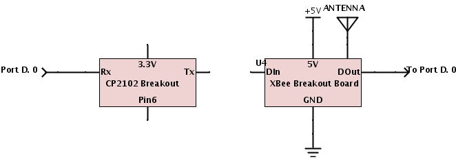
Receiving XBee and Serial-USB Schematic
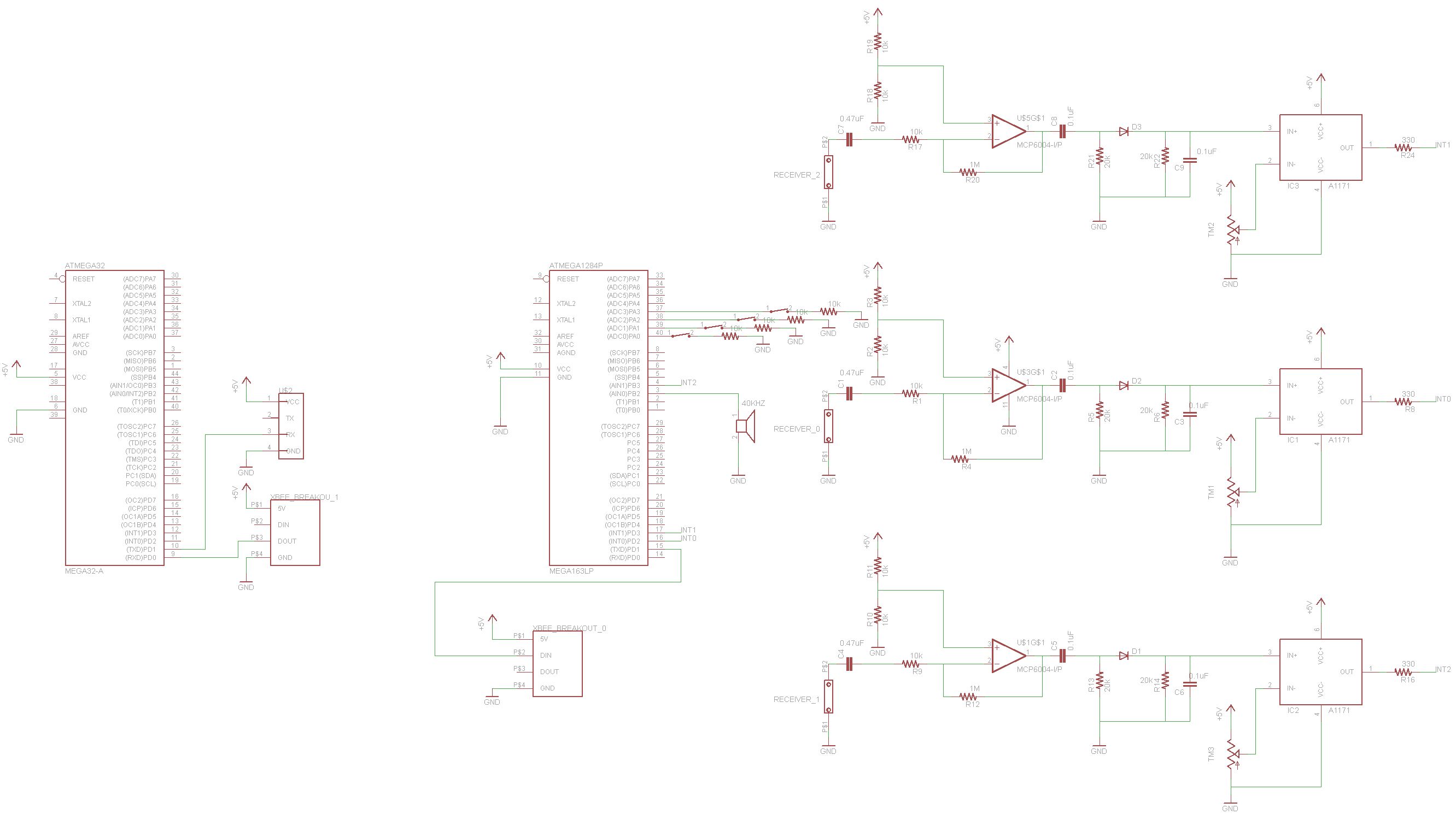
Whole Circuit Schematic
C. Parts List and Costs
| Part | Vendor | Cost/Unit | Quantity | Total Cost |
|---|---|---|---|---|
| 40 kHz Tx/Rx Pair (Part #139492) | Jameco Electronics | $7.95 | 3 | $23.85 |
| 9v Battery | Target | $1.57 | 1 | $1.57 |
| Prototype Board (Atmega 1284) | Lab Stock | $15.00 | 1 | $15.00 |
| Custom PC Board | Lab Stock | $4.00 | 1 | $4.00 |
| LF353N Op-amp | Adafruit Industries | $0.00 | 2 | $0.00 |
| LM311P Comparator | Lab Stock | $0.00 | 2 | $0.00 | Schottky P401 Diode | Lab Stock | $0.00 | 1 | $0.00 | Header Pin | Lab Stock | $0.05 | 8 | $0.40 |
| White Board | Lab Stock | $6 | 3 | $18 |
| XBee (Series 1) | Lab Stock | $0.00 | 2 | $0.00 |
| XBee Breakout Board | Lab Stock | $0.00 | 2 | $0.00 |
| CP2103 Breakout Board | Lab Stock | $0.00 | 1 | $0.00 |
| Atmega 32 | Lab Stock | $1.00 | 1 | $1.00 |
| Switch | Lab Stock | $0.00 | 1 | $0 |
| Diode 1N4001 | Lab Stock | $0.00 | 1 | $0.00 |
| 5V Regulator | Lab Stock | $0.00 | 1 | $0.00 |
| Button | Lab Stock | $0.00 | 4 | $0.00 |
| Poster Board | Lab Stock | $0.00 | 1 | $0.00 |
| Wires Resistors | Lab Stock | $0.00 | Many | $0.00 |
| Capacitors | Lab Stock | $0.00 | Many | $0.00 |
| LEDS | Lab Stock | $0.00 | Many | $0.00 |
| 16MHz Crystal Oscillator | Lab Stock | $0 | 1 | $0.00 |
| TOTAL: | $63.82 |
D. Division of Labor
The group has been functioning as a very effective unit. Both group members have participated in each step of the developing process of the project and have devoted tiredless hours into the lab work.
Qichao Shao
- General Hardware Design
- Soldering
- Mouse Unit Design
- Data Filter Design
- Wireless Module Design
Chaoping Deng
- Basic Algorithm Design
- Data Transmission Protocol Design
- HID Application Design
- Base Station Desgin
- Website Design
References top
Datasheets
- ATmega1284p Datasheet
- Ultrasonic Transceiver/Receiver Datasheet
- ATmega32 Datasheet
- Teensy 2.0++ AT90USB1286 Datasheet
- XBEE DataSheet
- CP2103 USB bridge DataSheet
Inspirations for Code/Designs
Vendors
Background Sites
Acknowledgements top
We would like to thank Professor Bruce Land for leading a great class, for teaching us how to approach problems, and lending hardware for our project. We would like to thank all the TAs for being always available at the lab and being patient with our problems. Many thanks to PhD candidate Justin Dobbs for helping us with the wireless component of the project.We would also like to thank Cameron, Andrew ,Jeff and Clifford for their HTML template. Lastly, we would like to thank all our fellow 4760 students for their help and contributions to a friendly environment in the lab .