"A running band with haptic temperature feedback to control your run."
For our ECE 4760 final project, we designed and built a running band that provides feedback to users with temperature and vibration.
This provides an unique way to monitor running habits with temperature feedback. The running band attaches to a user's upper arm and counts the number of steps the user takes. It then determines whether or not the user is moving at a desired cadence. The band produces a cold sensation when the user is not moving fast enough. The band vibrates if the user continues to be slow.
The band runs from an Atmel ATmega1284P microcontroller, a Peltier Plate, vibration motor, and various control circuits. Users operate a switch to determine if they want the band to operate in running or walking mode.
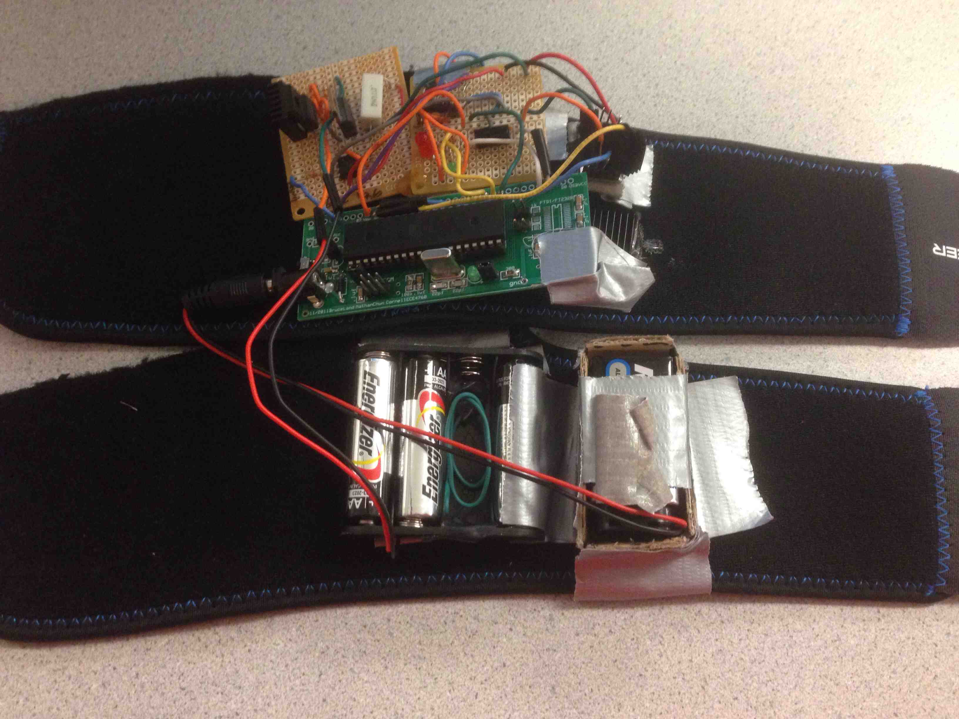
Our final project.
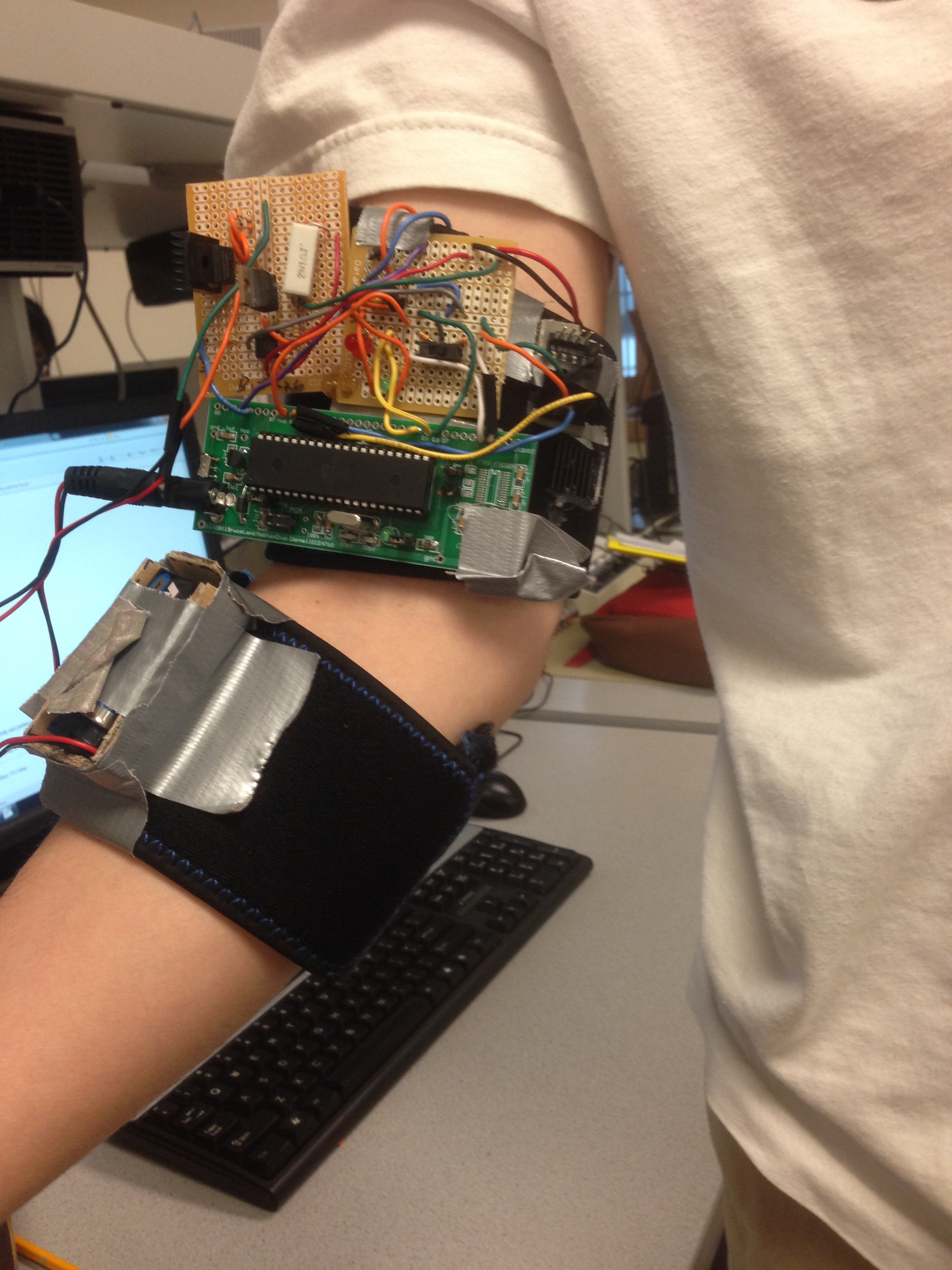
ColdRunner in operation.
High Level Design top
Overview
This project was developed by using our knowledge of microcontrollers and hardware design. We ran our device using an Atmega1284p device and attached devices such as a voltage regulator to control voltage from a battery pack, Peltier plate and vibration motor controlled by PWM and amplifier circuits and an accelerometer to measure rate of movement. We came up with the idea because it was a good way to monitor exercise while intuitively providing feedback to the user through temperature and haptic feedback.
Logical structures
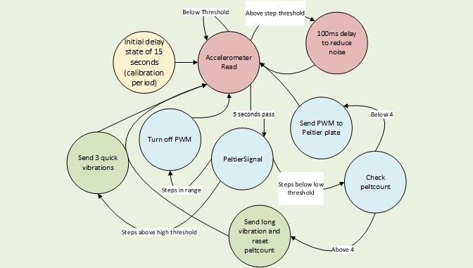
Our device operates first by taking in information from an accelerometer. This data provides information on the current acceleration of our device in two directions. Using this data, the device determines when there has been a massive change in acceleration, which we can say happens roughly when the user takes a step. Using this information, we estimate the user's current steps-per-interval (interval chosen to allow for adequate time to make an estimation). We compare this estimated steps-per-interval to one of two thresholds (walk or run) that is set by the user using a switch on the device. Either a red or green LED will light up depending on whether the device is in run (red) or walk (green) mode. The thresholds are set in the beginning during a 15 second delay period that also acts as a calibration period. The user's threshold is set during this time. If the steps-per-interval is lower than the threshold, we turn on a Peltier plate that cools the side that is in contact with the user.Once the user has increased the steps-per-interval to above the threshold, the Peltier plate will be turned off. If the user's steps-per-interval stays beneath the threshold for too long, a vibration motor will activate for a small period of time to give further feedback. If the steps-per-interval is higher than the threshold, we send three quick bursts from the vibration motor.
Standards
Though we did not find any official standard for the temperature for which extended temperature contact is safe, we found a reasonable metric from a NASA paper. The paper said that an extended period of -18°C(0°F) Celsius should be the cold threshold for unlimited contact. Our cold plate definitely does not reach this temperature. Though the warm side of the Peltier plate should not be touching the user's skin, it is still important to keep it on a temperature that would not harm the user if the user accidentally touches it. 45°C (113°F) is painful to touch for any period of time. We do not believe our Peltier plate hot side should reach these temperatures.
Relevant Patents and Copyrights
While working on this project, we found a couple of patents that could be similar to our design. These are Tactile feedback in an electronic device and Temperature feedback motion controller. The patent, Temperature feedback motion controller. is especially similar. However, this patent is used for controllers, especially video games, whereas our project is used for running or walking. The other patent, Tactile feedback in an electronic device could be applied to our project, but because it is worded so vaguely, we do not think our project infringes upon any intellectual property.
Hardware and Software Tradeoffs
The first major hardware and software tradeoff we made in our design was to use an analog accelerometer rather than an SPI protocol driven accelerometer. The advantage of this method was that we did not need to worry about following the SPI protocol and adhering to the restrictions it may provide. To use the analog accelerometer, we just needed to use the ATmega1284's built in analog to digital converter to get values from the signal received from the accelerometer. The downside to this tradeoff is that a SPI protocol controlled accelerometer may have given us more precise and structured results, but the design of our device did not require such precision so this tradeoff was acceptable.
A second tradeoff that we made for the device was to put the noise control of our device in the software part of the design. This meant that we put logic in our code to take out noise that may occur from a sudden change in acceleration that might cause the device to count extra steps that were not there. To make the software less complicated, we could have attempted to put the signal through a low pass filter of some kind, but we believed that a software solution would be easier to implement.
High Level Block Diagram
High-level block diagram.
User Interface
The most simplistic human control feature was the on/off switch. It simply controls whether to turn the system on or off.
A second human interface feature was a SPDT switch on the device that allows the user to set the steps-per-interval threshold to be a lower value for the walk mode or a higher value for the run mode. This allows the user to decide between two different options for a workout.
The third and most major human interface with the device is the accelerometer and haptic feedback system. The accelerometer reads the rate of movement from the human user and adjusts the vibration motor's rate of vibration and the Peltier plate's temperature to give feedback to the user to inform him that he is not running or walking fast enough.
The Accelerometer
The steps-per-interval value that we use to determine the rate of motion of the user is found through the acceleromter. The accelerometer gives three analog signals, one for each of the three accelerations in the x,y and z direction. However, we found that we only needed two of these directions to draw accurate results, so we chose the two directions that are easiest to read from when we mount the accelerometer on the user's arm (x and y).
The Peltier Plate
The Peltier plate is a plate that gets hot on one side and cold on the other depending on the direction and amount of current that we put into it. We had to make sure that the plate got cold enough such that the user can feel the cool side easily. However, when going to temperatures that low on one side, the other side gets equally hot, so we had to ensure that the heat from the hot side did not conduct to the cold side. To do this, we had to put a heat sink on the Peltier plate. This heat sink had to be attached with thermal adhesive that would not become loose when temperatures change.
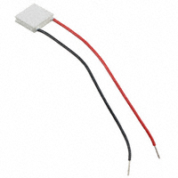
Our Peltier plate
The Peltier plate gets its cooling/heating function through a phenomenon named the Peltier effect, a type of thermoelectric effect. A thermoelectric effect is one that converts voltage provided into a difference of temperature. This effect was perfect for the device we wanted to create since it does not require any outside substance for a cooling effect other than the Peltier plate, which can be easily hooked up into our circuit. The polarity of the voltage or the flow of current is what decides which side of the Peltier plate gets hot and which side gets cold. A Peltier plate is constructed out of two conductors connected by a junction that removes or adds heat to one of the conductors and does the opposite to the other.
Furthermore, to control the temperature of the Peltier plate, we needed a PWM controlled current source. To do this, we used an optoisolator to keep the Peltier plate circuit separated from the microcontroller unit so that we would not damage the mcu if something went wrong with the Peltier plate. We also used a BJT to control the current going into the Peltier plate based upon the PWM.
Because this device is supposed to attach to your arm and the Peltier plate draws a lot of current, we needed to use a separate battery pack to power this part of the system that does not power the microcontroller. We used three AAA batteries and used a voltage regulator to get the desired voltage needed for the system.
The Peltier plate was given a max of about 0.7 Amps in our circuit. With a resistance of about 1 Ohm (given im the data sheet), we expect about 0.7 V to be across the Peltier plate during use. Because of the circuit it was connected to, we observed the Volts across the Peltier plate to be more around 0.5-0.6 Volts using a multimeter. This corresponds to about a 30 degree Celsius temperature differential. From what we observed, this was roughly the case with the colder side being around 10 degree Celsius and the warm side being around 40 degree Celsius. This adheres to the safety standard since the cold side is definitely not in the danger zone and the warm side is heat sinked so prolonged contact should not hurt since we want it to be below 45 degrees Celsius, which it is.
Hardware top
Hardware Overview
This project requires hardware to be built to control the external components such as the Peltier plate, vibration motor, etc. The Peltier plate control circuit is composed of a BJT, optoisolator and the Peltier plate. Furthermore, a voltage regulator is important to ensure the rail voltage for the Peltier plate is properly set. The vibration motor control circuit is important to allow a PWM to control it. The LED and switch component is also necessary to allow for the switching of modes. Finally, the accelerometer itself is attached to resistors to connect to the microcontroller ports.
Peltier Plate Control Component
The Peltier plate control component is run by a PWM. In our device, we send the controlling PWM from port B4 for the Peltier control. This PWM is sent to a 4N35 optoisolator, connected to a 330 ohm resistor. An optoisolator was chosen to protect the MCU from anything that the Peltier plate may do to damage it. The output of the optoisolator will then go into a TIP31 BJT. This TIP31 BJT acts as the voltage controlled current source that provides the necessary current to turn on the Peltier plate. A TIP31 was chosen because it was better rated to allow for this type of current control. To ensure that the TIP31 does not get too hot because it might be dangerous to place on somebody, we lowered the input resistance to the TIP31's base to be roughly 100 ohm. We also used a 1 ohm 2W rated resistor to connect the TIP31's emitter to ground to allow the collector current to be as high as necessary to run the Peltier plate. We determined that a current of roughly 0.68 A was good enough to allow the Peltier to be noticeably cold. A schematic can be seen in Appendix B.
The voltage rail for the voltage controlled current source needed to be 2.5 V. However, using just AA batteries, we could not get this voltage. To address this, we used a voltage regulator. For this purpose, we used a PQ30RV31 voltage regulator. This regulator takes in a voltage of 4.5 volts (3 AA batteries) and outputs a voltage of 2.58 V. A schematic can be seen in Appendix B.
Vibration Motor Control Component
The circuit for the vibration motor control component has two main parts, the BJT and the motor. We referenced a circuit that allowed us to use a PWM to control the vibration motor. This circuit is shown in Appendix B. The base resistor to the BJT was chosen to be 1 kOhm. To protect against possible voltage spikes that might occur from the motor, there is a 1N4001 diode placed across the motor as well as a small resistor in series with the motor.
The vibration motor and Peltier plate were both mounted on the inside of the armband. This can be seen below.
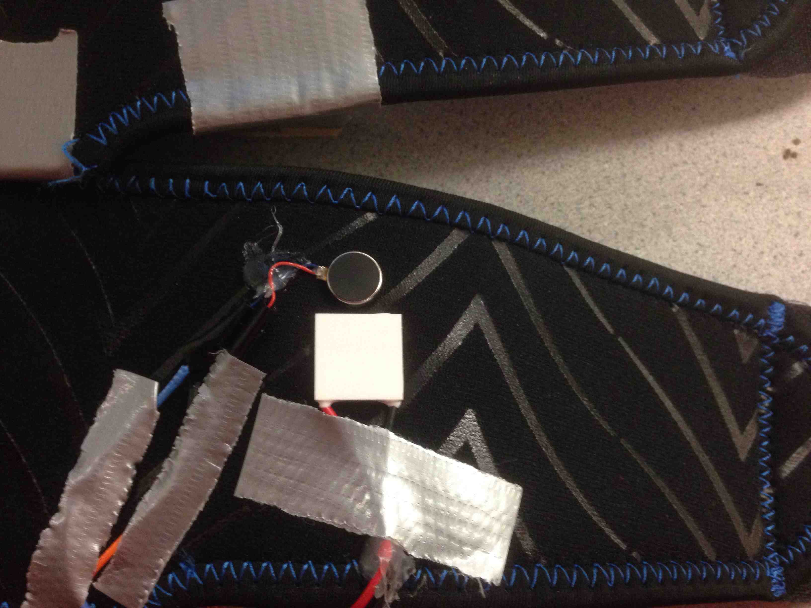
Peltier Plate and Vibration Motor
Threshold Switch and LED Component
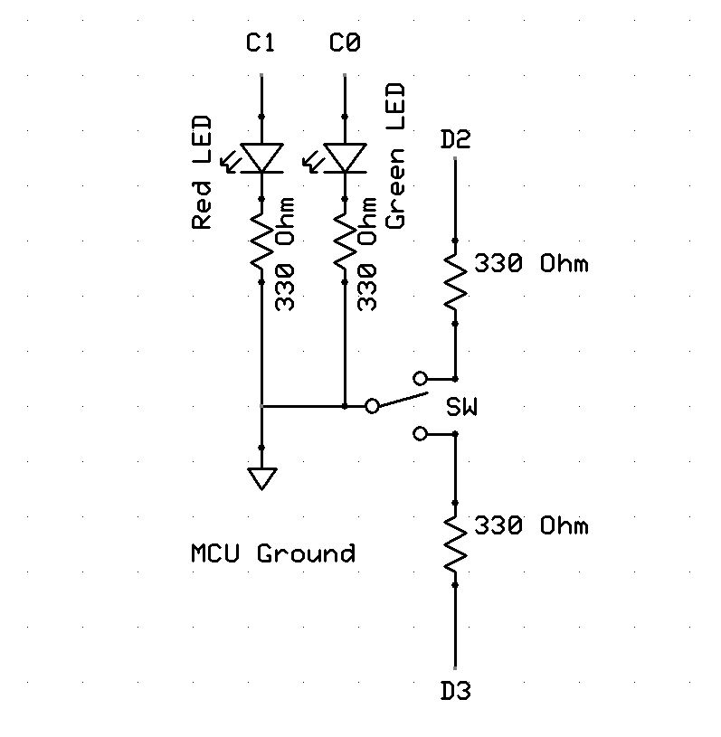
We wanted to allow the user to choose between a walking mode and a running mode. To do this, we used a SPDT switch. Since we have our microcontroller looking for an active low, we hooked the middle pin of the switch to ground and the two side pins of the switch to micrcontrollers pin D3 and D4. We then poll these pins frequently to determine which mode the users want to be in. To allow the user to see which mode he is in, we also have two LEDs (one green and one red) connected to ports C0 and C1, each through a 330 ohm resistor to control the amount of current flowing through. If the red LED lights up, the user is in run mode. When the green LED lights up, the user is in walk mode. A schematic can be seen in Appendix B.
Hardware Difficulties
One difficulty that we ran into when we were building the circuit was that the amount of current needed to be drawn for the Peltier plate would make the power dissipated across some of the components too much, and the components would become dangerously hot. For example, the reason we chose the TIP31 BJT was because some of the other transistors we used could not output enough current without requiring a much higher rail voltage. The TIP31 was able to give us a good ratio, but not without also getting quite hot. To fix this, we had to adjust the resistor values that we used. We found that the 1 ohm resistor at the TIP31 emitter and the 100 ohm resistor at the base worked well enough for us to run the Peltier plate well. The 1 ohm resistor also had to be a higher wattage resistor (we used a 2 W resistor) to make sure that it would not overheat as well, which we found would occasionally occur with other resistors that we tried to use.
In a related problem, the PQ30RV31 voltage regulator would also become very hot. After fixing the problem of the TIP31 getting hot, the voltage regulator would also become hot enough to be very uncomfortable to touch if drawing a large amount of current over more than twenty seconds. To help alleviate this issue, we attached a heat sink to the voltage regulator. This heat sink was useful in keeping the voltage regulator a good enough temperature to be safely mounted on somebody.
Another alternate design that we had was for the switch method for user control. Instead of using a switch, we considered using interrupt driven push buttons. The buttons would allow the user to increase the threshold manually. This created two problems. The first was that it would be difficult to transparently inform the user on what his current setting was without using another component such as a LCD display or multiple seven segment displays, which would add to the bulkiness of our physical design. The second problem was that to debounce the interrupt driven buttons, we needed to perhaps use an active high design in conjunction with low pass filters. It was much more intuitive for the user and for us to use the SPDT switch.
Another problem that we had to overcome was that the Peltier's hot side would start to affect the cold side if the temperature differential were too different. The heat would start to dissipate through the middle material separating the two plates. To fix this, we had to also attach a heat sink on the hot side. That way, the plate would be able to cool down without heat bleeding through from the other side. Otherwise, the user may not be able to feel the temperature feedback that the device is trying to give him.
The accelerometer was sensitive but mostly only in the specific directions that it is designed to measure accelerations in. Therefore, we had to be careful in mounting the accelerometer and making sure that it is always pointed in the correct direction. This is important in deciding the information the device receives.
One of the difficulties arises when it comes to the actual design of the full circuit mounted on the arm bands that we use to hold the device onto a person. The circuit itself cannot be too large, so we had to solder the components close together. Furthermore, we needed two separate battery sources to be mounted alongside the circuit, one to power the microcontroller and one to power the Peltier plate control circuit.
Software top
Code
ColdRunner.c
This file acts as the main of our program. It runs off of the Tiny Real Time (TRT) kernel, hosting multiple tasks necessary for our system. There are four main tasks: modeSelect, Accelerometer Read, PeltierSignal, and Vibe. These tasks will be discussed below. At startup, our code intializes the TRT kernel with a call to uart_init(). This function sets up the TRT kernel, initializes various tasks, semaphores, timers, and ports, and enables interrupts and puts the microcontroller to sleep. After this the TRT tasks begin to execute.
modeSelect
This task has the relatively simple job of determining what mode the system is in. It polls PIND to determine if the switch is set to a run or walk mode. After determining this, it sets a threshold (stepthresh) used later on for measuring steps, and turns on an LED. There are two LEDs which correspond to either a walk/run mode. The green LED represents the walking mode, and the red LED represents the run mode. This task has very short release and deadline times, so that any change in the switch can be seen quickly.
AccelerometerRead
This task was created to read in accelerometer values and measure if a step has been taken. The accelerometer that we used has an analog
output, which we capture with the microcontrollers onboard analog to digital converter (ADC). These values are captured from the
inputs PINA0 and PINA1. In order to capture these ADC inputs, we had to set up the ADC. This was done in
the uart_init() function. This task reads in the values by first ensuring that the ADC Start Conversion (ADSC) bit
and the ADC Control and Status Register A (ADSCRA) are equal. This is done to ensure that the ADC operation has finished. After doing this,
we store the ADC value in an integer (either Acx or Acy). This is done by writing the integer
with the value located in ADC Data Register(ADCH). After doing this, a new bit is written to the ADC Mux (ADMUX). This is done so that we can collect data on another channel of the ADC.
After setting the ADMUX bit, we write a 1 to the ADSC bit. This starts another conversion. We do this process twice in our task so that the
task will collect both the X and Y values. After collecting the X and Y acceleration values, two different operations occur. In the "run" mode
the values are added together and stored in a variable, avg. Then avg is compared to a past value of avg, prevavg.
We compare the |avg-prevavg| to a value to determine if a valid step occurred.
If the value of |avg-prevavg| is within the range, we update a variable stepcount. This absolute value operation is done to measure acceleration changes
relative to either forward or backward movement. After doing this, we
impose a 100ms delay, so that we do not read in false steps. A similar operation occurs during the walk mode, but instead of combining the
Acx and Acy value to form avg, we only set avg = Acx. This was done during testing our system, because we noticed
higher amounts of false steps occurring when avg is a sum of Acx and Acy. Apart from this change, the rest of the stepcount operations
are the same as the run mode. The task is updated every 5 ms, so that we are able to measure when acceleration changes occur. This was done because it produced the most accurate stepcount during testing.
PeltierSignal
This task sends a PWM signal to the Peltier plate. In order to do this, the task starts off by having an initial delay of 15 seconds.
This initial delay is created so that the user can get up to their desired speed after turning the system on. The delay is also used to set the user's individual threshold. This is done so that the thresholds for the user
is tailored to their individual running paces. This is done by averaging accelerometer reads after the delay period is over. After the delay, the task will compare
a step count, stepcount to a threshold, stepthresh. stepcount is determined every 5 seconds. It is updated during this time from the task AccelerometerRead. stepthresh is set from the task modeControl.
If stepcount is above the stepthresh, then the output OCR0B is set to 255. This will not trigger the PWM. However,
if stepcount is less than stepthresh, a new variable is set to 1 (peltthresh). If peltthresh is 1, a PWM will be outputted.
OCR0B is set to 0, so that the PWM will turn on the Peltier plate. After this occurs, a variable peltcount is added to. This variable
was initialized to 0. However, if peltcount goes above 3, the OCR0B is set back to 255. This is done to prevent heat flowing back onto the Peltier plate.
However, because the Peltier plate is turned off, the system still needs a way to alert the user that they have been running too slow. This is done by triggering the task Vibe.
Vibe
This is the last task in the ColdRunner.c file. This task checks to see if a variable vibe has been set. If it has been set when the operator is below their low threshold, it sends
a PWM to OCR0A at a value of 0. This task turns on the vibration motor for .7 seconds, so that user has enough time to feel the vibration, without it being too annoying. If the variable vibe has been set
when the operator is above their high threshold, a 0 PWM signal is sent to OCR0A. This is sent in 3 short bursts, so that the user has time to differentiate between a high and low threshold.
trtkernel_1284.c
This is used to run the TRT kernel. This sets up the kernel and contains functions for all the trt* methods.
trtSettings.h
This is a header file used to define various things in TRT, such as max number of tasks or semaphores. It is also used to specify the MCU's clock and UART baud rate.
Software Difficulties
Throughout this project we had some difficulties on the software side. These difficulties usually revolved around timing and reading in variables.
One of our major challenges was with the timing for the tasks. These were difficult to determine at first, because we were unsure how much
data we needed before we could conclude that we had an accurate measurement from the accelerometer. This involved trying different times for release time in the
AccelerometerRead task. We had started with .1 seconds, but eventually realised that the threshold needed to be lowered to about 5 ms. This was due in part
to the fact that we would often miss the acceleration changes with a time of .1 seconds. After lowering the acceleration timing down to 5ms, we also ran into the issue that
we would get too many acceleration values, which led to our 100ms delay after a high read.
Another timing related issue occurred with our PeltierSignal task. This was originally set to a very high release time value, so that we could compare
the number of steps taken with a threshold. We believed that setting this to a large time would allow us to accurately see steps/min. However, this led to long delays in sending
the PWM to the Peltier, and we wanted more control to do this. This led to us lowering the release time of this task to 5 seconds. This allowed us to achieve the control of the
Peltier plate that we desired, along with fairly accurate step/min counts.
Results top
The device can readily be used to monitor a user's approximate running pattern and run under two different modes and provide feedback to the user in a quick manner. The user can switch between the two modes quickly and seamlessly. The device is easy to attach and needs to run off 3 AAA batteries and one 9-V battery. To provide feedback, the device uses two noticeable haptic feedback components. The first feedback component is the Peltier plate, which is in contact with he skin of the user. The Peltier plate can quickly cool down to temperatures easily felt by the user within three seconds. It updates itself frequently as well to allow for accurate feedback. The second feedback component is a vibration motor. It vibrates periodically if the user is not meeting the required rate of motion that the setting the device is set to demands. Under testing, the device ran well and gave the expected responses to correspond to the input that the user gave it.
Speed of Execution
The device runs off of multiple tasks using the TRT kernel that we used during our ECE 4760 coursework. We scheduled our tasks as follows. The accelerometer is read every 0.005 seconds. We found that this gives us a reasonable rate of information. However, we have to account for some double counting, which we do by using a built in hesitate to ensure that only one step is read when one step is expected. We update the Peltier plate based upon our accelerometer readings every 5 seconds. The vibration motor is activated every 20 seconds for a short half second burst if the Peltier plate has been on the for the previous 20 seconds. This is used for an extra reminder to the user.
Safety
Hardware Safety
Because our device promotes movement and is connected directly to the arm of the user, we wanted to make sure that the chances of injury ia small. We use an elastic band to attach the device to the user. The elastic band should be tight enough such that the device will not fall off easily and the band is still comfortable enough such that the user has unrestricted motion. We kept the wirings short so the chance of tangling them up and damaging the circuit or hurting the user is decreased. Another point of emphasis to ensure safety for the user was the use of a heat sink to keep the Peltier plate from becoming uncomfortably or dangerously hot. The heat sink keeps the Peltier plate at a good temperature. We also made sure to not allow more than 0.7 amps to flow into the Peltier plate so that it would not become too hot. Another important component that we heat sunk for safety was the PQ30RV31 voltage regulator which would become very hot whenever we ran the Peltier plate at our self-imposed 0.7A maximum current. The heat sink definitely helped keep that component from becoming too hot to place in our circuit.
Software Safety
To ensure that none of the components received improper values, we had to ensure that the variables were set correctly at all times. Since we used
tiny real time for our device and ran multiple tasks that ran at vastly different speeds, it was very important to protect the global variables that are
accessed across different tasks. To do this, we used a semaphore. We used a semaphore SEM_SHARED that would protect variables that needed to be
read and written across different concurrent tasks, such as the threshold for number of steps, the number of steps we counted, and the Peltier plate and vibration
motor settings.
Usability Across Multiple Users
Our device is meant to be used by people who wish to either walk or run. Since we use an elastic arm band, we expect that it can easily fit on the arms of people of varying sizes. The only problem we foresee in fitting this on someone's arm is if they have arms/biceps that are very wide in girth (obese or bodybuilders) or arms that are too thin such that the band has trouble grasping the arm tightly (very young children). The feedback modules are positioned such that if the band fits, then the person should be in contact with the feedback components. Since our device is attached to the arm, we believe that it could be used to sense motion for the handicapped who cannot run but may still want to use it to monitor arm movement. This would require changes in the threshold values but should be doable. For those who need to attach this device to the leg, the device should work as well but needs to be adjusted for more consistency to correspond with being on the leg but that should be a viable use for our device.
Conclusions top
Summary
The purpose of the project was to create a temperature feedback device that aids a runner in determining whether he or she is moving at a reasonable rate. This project was able to accomplish this goal through the use of a Peltier plate, accelerometer, microcontroller, and vibration motor. This project was very similar in what we set out to do, along with the inclusion of the vibration motor, which we felt added to the project. Overall, we felt that we accomplished something very in line with our proposal.
However, some things about our final design were different than we envisioned. We did not make use of the digital potentiometer, and did not control the Peltier plate over a range of values. Our power control circuit was difficult to implement, and it would have been much harder to develop another system that could give us the control that we truly wanted. We were able to achieve slight control by altering the PWM signal sent to the Peltier circuit, but we decided not to include this in our final design. This exclusion was due to the fact that the variable PWM did not produce a cold enough temperature on the plate. In addition to this, we felt that the full device itself was slightly more "clunky" than we hoped it to be. We did not think that the batteries would take up so much room, and expected the device to be somewhat sleeker. Despite this, we were able to achieve our desired results.
The last thing that we felt could have been different was our placement of the running band. Originally, we wanted to put it on our arm, and we ended up doing this. However, after working on our project we wanted to put the running band on a user's legs. During testing, this gave much better accelerometer readings and step counts. We were not able to do this though, because when placed on a user's leg, the running band slides down very easily. This sliding heavily degrades performance with respect to the Peltier plate and the vibration motor. So, in the end, we resulted back to our original idea of placing the band on the arm.
Intellectual Property Considerations
There are a couple of intellectual property considerations for our project. First, we reused the TRT kernel and settings code from labs 3 and 4. This code was made freely
available to us and was written by Dan Henriksson and Anton Cervin with modifications done by Bruce Land. Additionally, we used the trtUart.c and
trtUart.h files extensively during testing. These files were written by Joerg Wunsch and licensed via "The Beer-Ware License". These files were also modified
by Bruce Land and Jeff Melville. Another area to consider for intellectual property was our vibration motor control design. We based our circuit heavily off
of a circuit provided on this website. This was in the public domain, so we do not think
that this imposes on any IP considerations.
Ethical Considerations
Our design is meant to be attached to a user during use so we had to be careful in its design so that it would not injure a user. This required following safe conduct during our design period, our building period, and our testing period. We looked at the IEEE Code of Ethics to ensure our conduct was to the highest standard. We did not have any conflict of interests in designing and working on this project. Each member held the other to a good standard of conduct. We referenced all the sources of codes or designs that we used. All information on this web page is written to be accurate to the best of our knowledge. Because we use a Peltier plate to cool a person down, we need to make sure that the hot side of the Peltier plate both does not get too hot or come into contact with the user when too hot. Furthermore, we need to ensure the components are not dangerous to handle. We believe we exercised all the necessary ethical precautions that this project requires.
Safety and Usability
There are some safety considerations with having a device(Peltier plate) that can rapidly change temperature pressed against a user's skin. In our case, we built our power circuits and software for the Peltier plate to limit any potential harm to the user. In software, the Peltier plate is limited to being on for only 20 seconds at a time. Additionally, the power control circuit for the Peltier plate limits the amount of voltage and current that the Peltier plate can receive, so that maximum temperature the device can reach is relatively low. Lastly, the Peltier plate's cold side is the only side applied to human skin, so that no one can receive a burn from high temperatures.
This device is not intended to be used by people with physical or mental disabilities. The user interface of the system is very easy to use, and only requires toggling a switch.
Legal Considerations
As far as we know, there are no legal considerations for this project.
Appendices top
A. Source Code
- ColdRunner.c (6 KB)
- trtkernel_1284.c (5 KB)
- trtSettings (1 KB)
B. Schematics
Our schematics are listed below.
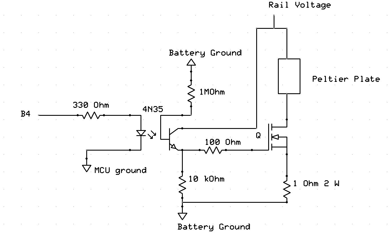
Peltier Control Circuit
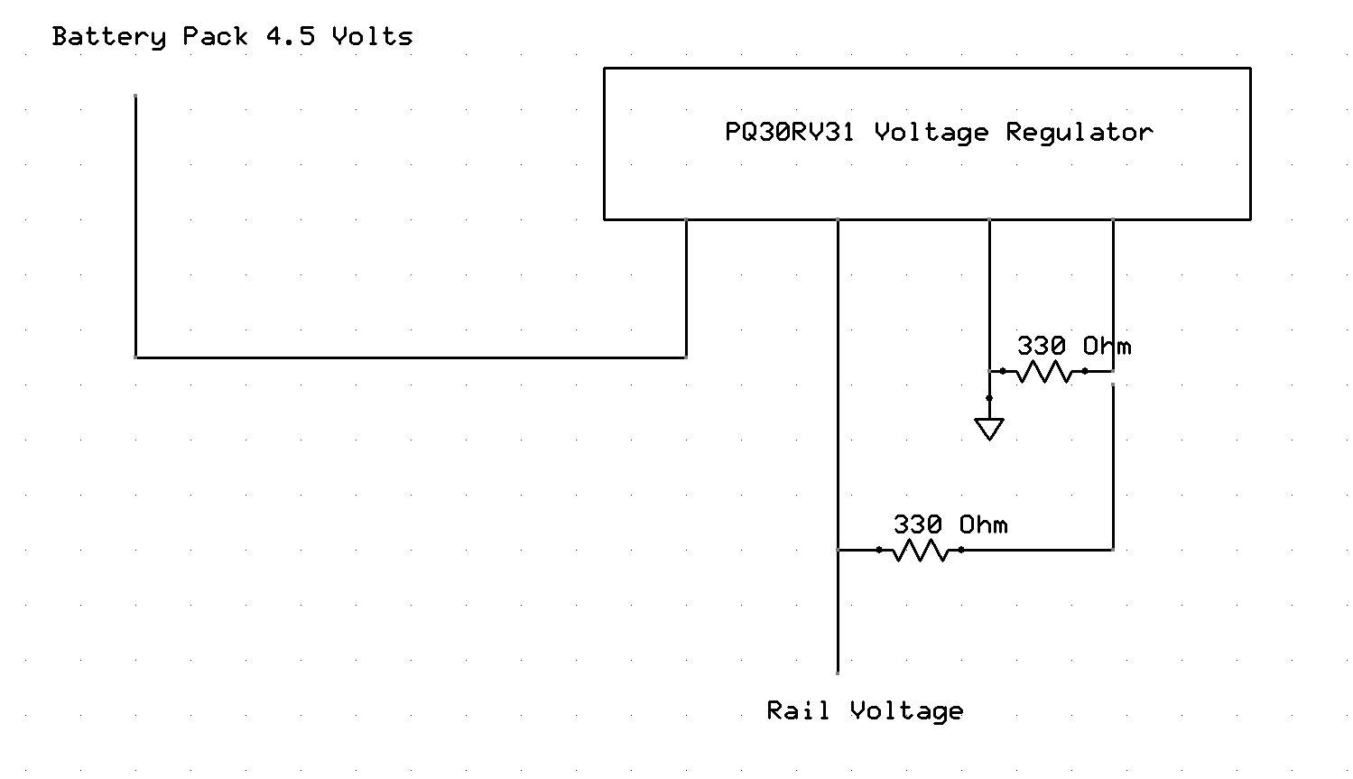
Voltage Regulator
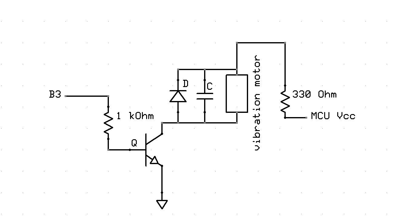
Vibration Motor Control Circuit
Switches and LEDs
C. Cost
Our total cost for this project came out to be $56.84. The majority of this cost came from our Peltier plate, accelerometer, and arm band. Our cost breakdown is listed below.
| Part | Source | Unit Price | Quantity | Total Price |
|---|---|---|---|---|
| Vibration Motor | Adafruit | $1.95 | 1 | $1.95 |
| Thermal Paste | Amazon | $8.00 | 1 | $8.00 |
| 9V Battery | Anywhere | $2.00 | 1 | $2.00 |
| AA Battery | Anywhere | $0.00 | 3 | $0.00 |
| Peltier Plate | Digikey | $14.84 | 1 | $14.84 |
| Mega1284 | ECE 4760 Lab | $5.00 | 1 | $5.00 |
| AA Battery Holder | ECE 4760 Lab | $0.00 | 1 | $0.00 |
| Voltage Regulator | ECE 4760 Lab | $0.00 | 1 | $0.00 |
| NPN Transistor | ECE 4760 Lab | $0.00 | 1 | $0.00 |
| Resistors | ECE 4760 Lab | $0.00 | 13 | $0.00 |
| Capacitors | ECE 4760 Lab | $0.00 | 1 | $0.00 |
| MOSFET | ECE 4760 Lab | $0.00 | 1 | $0.00 |
| SPDT Switch | ECE 4760 Lab | $0.00 | 1 | $0.00 |
| LED | ECE 4760 Lab | $0.00 | 2 | $0.00 |
| Optoisolator | ECE 4760 Lab | $0.00 | 1 | $0.00 |
| Header Pin | ECE 4760 Lab | $0.05 | 23 | $1.15 |
| Accelerometer | Modern Devices | $10.95 | 1 | $10.95 |
| Heatsink | Previously Owned | $0.00 | 2 | $0.00 |
| Elbow Pad | Target | $12.95 | 1 | $12.95 |
| Total | $56.84 |
D. Division of Labor
| Casey Mak | Both | Ian Purnell |
|---|---|---|
| Peltier Plate control circuit | General software debugging | Interfacing with accerleromter and vibration motor |
| Developing power compliant circuits | General soldering | Software design for accelerometer/vibe/mode |
| Peltier control code | Website Content | Website Formatting |
| Assembling finished product |
References top
This section provides links to external reference documents, code, and websites used throughout the project.
Datasheets
- Peltier Plate CP30138
- ATmega1284 Microcontroller
- Accerlerometer MMA7361L
- Voltage Regulator PQ30RV31
- TIP31 BJT
- Optoisolator 4N35
References
Vendors
Background Info
Acknowledgements top
We would like to thank Professor Bruce Land for providing help and guidance whenever we needed it. We would also like to thank all the lab TA's who helped to solve some of our most challenging and basic problems.
Finally, we would like to thank Paul Swirhun and Shao-Yu Liang of Spring 2011's Pace Clock Project for the use of their webpage as a template. Without it, our webpage would be very unpolished.