Introduction top
"This device allows friends to learn songs, create their own songs, and collaboratively merge them."
Our final project for ECE 4760 is a fully customizable button keyboard that has a variety of features to allow for collaborative music-making between friends. Each keyboard has eight fully programmable buttons; any button can play any valid MIDI note and there are 16 customizable instrument sounds, all created using FM synthesis. Our device allows for real-time MIDI recording and playback, so that you can experiment with different harmonies and melodies. After recording a melody, you can also play it back in the exact pattern you played it using our MIDI synthesizer. The biggest collaborative feature of our device is the ability to send recorded MIDI tracks to a friend using the same device through IR transmission, such that you can hear the melody they created and superimpose your melody on top of theirs. The device is able to record up to four simultaneous channels, each of which can have its own instrument and play up to three simultaneous notes; this way, friends can send melodies back-and-forth to each other to create tone-rich songs. Lastly, we have a teacher mode, where the user plays along with preprogrammed songs. After playing it, they will receive feedback on how well the song was recreated. By using this mode, the user will be able to play the melody perfectly after some practice.
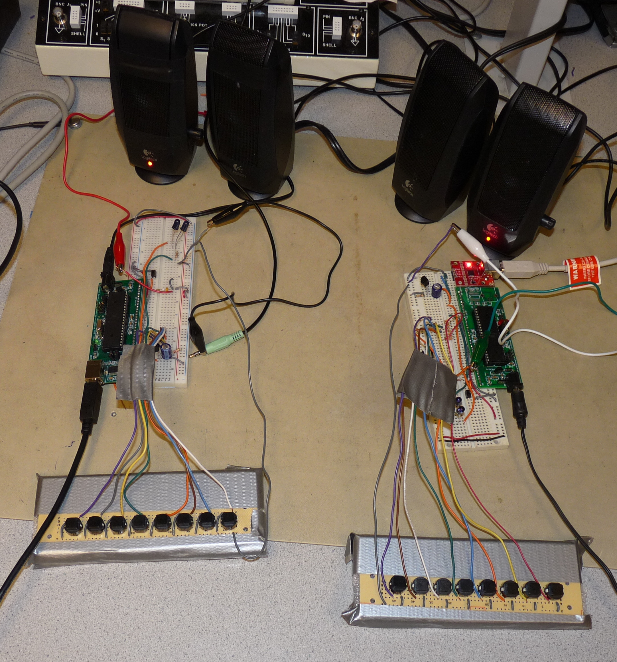
Figure 1: Two DJ Party prototypes.
Project Overview top
Motivation
The goal of our project is to allow users to enjoy music as much as we do. Both of us are musicians, and we often find it difficult to find time in our busy schedules to meet and make music. Our project allows us each musician to create his or her own part of a song, send it to a friend, and have a friend add another part at a later time. To further foster music creativity, we added a teacher mode that allows users to hear a song and attempt to play it back by ear. The prototype will give the user feedback on how well he or she was able to play the song, allowing the user to become better at the song.
Our prototype uses a variety of concepts learned in ECE 4760 and other classes. Since our project is targeted for DJing, we decided to use FM synthesis to create modern electronic sounds. The prototype uses pulse-width modulation and direct digital synthesis to play back music. To persist songs, we implemented our own MIDI library which produces valid MIDI streams and is able to playback a subset of MIDI. We wrote additional algorithms to merge MIDI tracks (for collaboration) and compare the similarity of MIDI tracks (for teaching). This library was extensively unit tested to ensure accuracy. Finally, for wirelessly transmitting tracks between prototypes, we used IR LED transmission adapted from previous work for ECE 4760. We implemented a transfer protocol based on TCP/IP to ensure reliable data transfer.
Background Math
Direct Digital Synthesis
Direct digital synthesis (DDS) uses the concept of an accumulator, an increment, and a wave table to create a digital signal. On a high level, we create a wave table, which has the values of a 2Π periodic wave from 0 to 2Π scaled to an amplitude of our choosing. Assume for simplicity that the wave table is a sine wave. As we move through the inputs to the sine table, the outputs move through the sine wave. If we make larger jumps through the table, we will output fewer samples before we reach the end of one period of the sine wave. At a constant sampling frequency, a sine wave with fewer samples will be reconstructed into a sine wave with a higher frequency. Thus, we can alter the frequency of the output sine wave by changing the interval of the jumps through the table. To move through the sine wave in software, we use an increment, which dictates how large of a jump through the sine table we move at each time tick, and an accumulator, which keeps track of where we are in the sine table. Note that time ticks happen at sampling frequency of our choice. To make the accumulator "periodic," we leverage software overflow: we can make the accumulator a 16-bit unsigned integer. Accumulator at 0 means that we are at sin(0) and accumulator at 216 - 1 (its max value before overflow) means that we are as close to sin(2Π) as can be. Once the accumulator overflows to zero, we are back at sin(0). Leveraging this fact, we can set the increment to a specific value in order to get the output sine wave to a desired frequency. Figure 2 below shows the equation we used to choose our increment value,
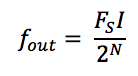
Figure 2: Output Frequency Formula
where fout is the resulting frequency of the output sinusoid, Fs is the sampling frequency, which is 8 kHz in our case, I is the value of the increment, and N is the number of bits in the accumulator (16 in our case). The number of samples in an output sine wave depends on the size of the increment. For instance, if the increment is 1, then it will take 216 - 1 samples before the accumulator overflows and starts the next output sine wave. To ensure that you have at least S samples per output sine wave, the increment must be restricted to < 216 - log2S bits, which means that the output frequency is restricted to Fs / S. Note that triangle and sawtooth wave can be constructed the same way. If the 2Π periodic sine wave is replaced with any other 2Π periodic wave, direct digital synthesis will output that waveform instead.
FM Synthesis
We chose to use FM synthesis to create different sounds. Since our project is aimed at DJs, who are accustomed to using button boards to create music, we were able to leverage the many electronic-sounding instruments that FM synthesis can produce. The FM synthesis equation we use is:
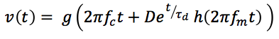
Figure 3: FM Synthesis Formula
where functions f and g may be 2Π-periodic sine, sawtooth, or triangle waves. Note that the waveform has two components: a carrier frequency fc, and a modulation component, fm. The modulation component provides interesting, electronic-like sound. Users can select different "instruments" that change the functions represented by f and g and modify the values of D, τd.
High-Level Block Diagram
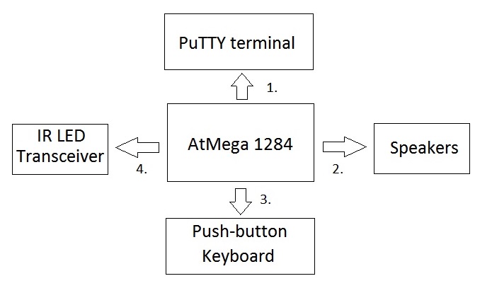
Figure 4: High-level block diagram of our project.
1. Command Line Interface
The user issues commands to the prototype via a PuTTY terminal on a Windows computer. The computer is connected to the MCU via a USB cable into the MCU's USART0. The characters from the command are sent serially via standard USB communication protocol. The user is given a list of commands to issue to the prototype, such as "record" or "learn" and enters them into the PuTTY terminal. The user receives his or her feedback from teacher mode in the terminal.
2. Speakers
We use direct digital synthesis to create sound, so the output of the MCU's pulse-width modulator (port B.3) is low-passed and connected to standard computer speakers via alligator clips.
3. Push-button Keyboard
The user plays music via a push-button keyboard, which is an array of active-low buttons: each button is an short circuit when pressed and an open circuit when released. We enabled the pull-up resistors on port C on the MCU and wired each button to a port C pin.
4. IR LED Transceiver
We use USART1 on the MCU to serially transmit and receive MIDI streams from other prototypes. We transmit the streams via packets, and each packet is transmitted using a protocol adapted from ECE 4760 Lab 3. Since a typical MIDI stream consists of many packets, we use an algorithm based on TCP/IP to resend dropped packets.
Design Decisions
Microcontroller
The primary design constraint that we encountered was internal SRAM size. Since we chose to use an SMPTE-time type MIDI, each stream would require 2-bytes for each 10 milliseconds of track time. If we include additional header overhead and other MIDI events in the stream, even 16 kB of RAM proves small. Thus, we decided to use the AtMega 1284p, since it had the largest RAM capacity of the AtMega series.
Transceiver
We weighed a variety of factors when choosing IR LED as the medium for transmitting and receiving MIDI data: cost, required research, and reliability. The low cost of 2 IR LEDs and 1 IR receiver per prototype made an IR LED transceiver especially appealing. Since we needed to build two prototypes for demo, low-cost was paramount. Second, since we had already used IR LED transmission in a previous lab, we were very familiar with how it worked and what we would need to do to get it working on our MCU. Finally, testing performed by Bruce Land revealed that in a 3-meter range, the packet loss rate for the Lab 3 IR transmission configuration was less than 0.1%.
Sound Encoding
We chose MIDI to encode songs because it's highly compressed and universally used. Choosing an industry standard gave us confidence that we would not have any unnoticed edge cases in a custom encoding, and our tests for the library could be decoupled from the integrity of the encoding. Using an industry standard also ensures portability if we wish to interface future version of our prototype with other MIDI devices. Finally, MIDI files are much more compact than even the most popular compressed audio formats such as MP3. Since the AtMega 1284p only has 16 kB of RAM, this is crucial to allow us to use on-chip RAM exclusively.
MIDI Time Scale
MIDI has two ways to express time intervals in the encoding: relative time and absolute time. Relative time is expressed in a time signature, which has units beats per minute (BPM). A status byte is encoded into the MIDI file 24 times per quarter note. The benefit of relative time is that you can change the tempo of a MIDI song by only changing the time signature status byte--the rest of the file needs not be changed. Absolute time has no concept of time signature; rather, it issues a 2-byte time tick called a quarter frame message, which is issued 4 time for frame, or every 10 milliseconds in our prototype. Although tempo is not easily changed, recording user input is much easier, as the prototype has no way of knowing what tempo the user desires. Even if he or she inputs a tempo, it is unlikely that the user will be able to hold a constant tempo (it is very hard!). Thus, playback would inevitably differ from recorded input. For this reason, we chose to use absolute time.
Standards
International standard "IEC (EN DIN) 60825-1 SAFETY OF LASER PRODUCTS - Part 1" restricts laser products emitting coherent laser radiation. The TSAL6400 does not violate this standard according to Vishay's documentation on eye safety with respect to IR LEDs. Our generated MIDI streams comply with MIDI standards.
Copyrights and Patents
Our project does not have any relevant copyrights, patents, or trademarks associated with it. Our software uses open-source protocols such as MIDI and borrows from open-source protocols such as TCP/IP. We could find no relevant patents for MIDI sequencers or synthesizers that resembled our software implementations, and the teaching algorithm that we wrote uses bounded linear search, which is not patented. All other software is borrowed from ECE 4760 labs; we are free to use it, but we cannot patent it. Our IR transceiver hardware is borrowed from ECE 4760 Lab 3, so we are also free to use it but unable to patent it. Our button keyboard is a simple array of active-low buttons, which is not patented and likely too simple to patent.
Hardware Design & Implementation top
For our project, we used hardware to implement many of the core functions of our project. To be specific, we used a push-button keyboard that would generate sounds when pressed, a low-pass filter on the output of the PWM to actually produce the sounds we wanted, IR LEDs and receivers to be able to wirelessly transmit MIDI files from board to board, and finally, we used USART communication with a computer to select what mode we wanted to enter. See the "Appendices" section for complete circuit schematics.
Push-Button Keyboard
The push-button keyboard is the main interface for a user of our project. They can play melodies, experiment with sounds, and add onto existing MIDI files. The keyboard is simply push buttons that were soldered onto a board and connected to the eight ports of Port C. The pull-up resistors of port C are enabled to ensure the pins are never floating. Thus, when the button is pushed, the pin is shorted to ground, and when the button is released, the pin is pulled up to Vcc. Thus, the buttons are active low. We connected one button to one port because we wanted to be able to play several notes at the same time, so we need one bit for each button to ensure any possible combination of buttons can be decoded.
Low-pass Reconstruction Filter
To produce the sounds we wanted, we put the output of the PWM into a low-pass filter and passed the resulting wave into the speakers. We used the same resistor and capacitor values from Lab 2 (20kΩ resistor and 10nF capacitor), which also used DDS to create sound. These values gave us a cut-off frequency of 7.2 kHz, sufficient to filter out the 62.5kHz carrier frequency from the output of the PWM, while passing and reconstructing all frequencies we can produce. Although our filter is able to pass C8, the MIDI note with the highest frequency of 4186 Hz, the frequency of our Timer1 interrupt for direct digital synthesis limits our highest note to B7, which is 3951 Hz (see: Direct Digital Synthesis in Software).
IR Transmission
We used the set-up of Lab 3 for our IR transmission, including the TSOP31456 receiver and TSAL6400 IR LEDs. We needed to send a few kB of data each time, so to ensure reliable transmission, we created a finite-state machine similar to TCP/IP. This is discussed further in the software section. We used a baud rate of 4,800 Hz and each character sent was seven bits with two stop bits. We picked a data payload of 64 bytes; larger payloads are more efficient, but a payload too large would decrease reliability. We decided that 64 bytes balances both trade-offs well. We used a 100Ω resistor for the IR LED circuit such that the current through the IR LEDs was 25 mA (current = 2.5V / 100Ω). Circuit diagrams of the IR LED and receiver can be seen in Figures 5 and 6.
USART Transmission
We interfaced our PuTTY terminal and the MCU using the MCU's USART0. One of our prototype boards had a presoldered USB input for USART communication; we added a CP2102 Breakout to the other prototype. We chose to use USB and USART communication between the MCU and PuTTY because it is inexpensive and reliable. We interfaced our IR transceiver with the MCU using the MCU's USART1. We needed to change our serial frame format for the MCU's USART1 based on the limitations of our IR receiver hardware. According to the TSOP34156 datasheet, "after each burst which is between 6 cycles and 70 cycles a gap time of at least 10 cycles is necessary." Since the TSOP34156 transmits data directly to our USART, this means that our USART serial frames must maintain this ratio. To do this, we chose to have 7 data bits and 2 stop bits per serial frame, putting our serial transmission well within this hardware limitation.
Hardware Limitations
A challenge we faced was the restrictions hardware imposed on us. We initially wanted to use RC5 encryption for our IR communication, but after doing research and looking at sample code online, we realized that sending RC5 messages was extremely complicated and depended on very accurate timing. In this case, both the hardware and software limited our ability to implement this method of communication. Another example is the button keypad we used; originally we wanted to use the 16-button telephone keypad used in Lab 2 to interface with the user and create tones when pressed. However, we soon realized that it was impossible to detect the difference between two or three (or more) button presses if the buttons were all in the same column and row; this is due to the matrix nature of the keypad, since the third button press would connect wires the first two buttons already connected. Since we wanted to be able to play at least three buttons at a time, this keypad was unusable for our design; as a result, we created the keypad we used in the end. Another similar limitation was using just eight buttons on the keypad we used instead of the 16 we wanted; the reason for this was the number of ports on the MCU. We needed to connect each button to a different port, but we did not have enough unused ports to implement this. Lastly, we wanted to have the ability to play longer songs, so we planned on using DataFlash for more memory. However, after looking at sample code, we realized that this was not a easy task and the benefit of longer songs was not worth the time to implement it. Additionally, we mixed up the order for the DataFlash part, so it did not come in until we were done with the rest of our project. As a result, we did not implement DataFlash to hold longer recorded songs.
Software Design & Implementation top
Software Overview
We programmed our MCU using C that was compiled with the WINAVR GCC C compiler. We split our software into many different files due to the large amount of code required to implement all of the prototype's features. An overview of the different functionalities is below:
Command Line Interface
The user controls the modes of the prototype via a command line interface in a PuTTY terminal. The user can input the following commands:
| Command | Description |
|---|---|
| inst | Change the instrument of the current recording track. |
| but | Change the note that a button on the keyboard plays. |
| rec | Begin recording a track to be merged with any existing saved tracks. |
| play | Simultaneously play back all saved tracks. |
| learn | Choose a song to hear and emulate. User will be rated on emulation performance. |
| erase | Erase all saved tracks. |
| send | Send all saved tracks to another prototype. |
| receive | Receive tracks from another prototype. |
The user will be prompted to enter a command upon power-on and after completion of a command. The user can press the button wired to port B.2 which will trigger an external interrupt that terminates any command and return the command line interface at any time. The command line interface (CLI) is able to interact with the user by printing to stdout and scanning from stdin using the uart.c library. The software itself is a large if-else block, which verifies the user input on each command and sets the appropriate flags and exits when a valid command is received. Interrupts are disabled within the CLI code to prevent the button from bouncing and triggering multiple calls of the CLI function and to stall essentially all execution of other commands while in the CLI. This prevents any undesirable changes from happening while interacting with the prototype.
Direct Digital Synthesis
To create sound, we used direct digital synthesis (DDS). We used the pulse-width modulator (PWM) output and a reconstruction lowpass filter to create analog sound that can be passed to typical computer speakers. In the fast-PWM mode on the MCU, the output of port B.3 is high when register OCR0A is lower than the Timer0 counter (TCNT0) and is low when OCR0A is less than TCNT0. Since we used Timer0 at its full rate of 16 MHz, the 8-bit TNCT0 overflows at a rate of 62.5 kHz. Thus, the output of the PWM is a square wave whose duty cycle is modulated by OCR0A. As explained in the "Lowpass Filter" in our hardware section, running the PWM through a lowpass filter creates a constant analog signal whose voltage is directly proportional to the PWM duty cycle. Thus, we can use DDS to control the PWM and create a digital signal. We perform DDS as explained in the "Background Math" section using the equation in Figure 2. We call our Timer1 interrupt at a rate of 8 kHz: this is the minimum frequency required to play all MIDI notes (except C8). We want our ISR frequency to be as low as we can make it so we have a longer deadline for DDS and FM synthesis math. Thus, 8 kHz will be our sampling frequency Fs. We maintain accumulators and increments as 16-bit integers, and three in-memory wave tables which map 2Π periodic sine, triangle, and sawtooth waves to 0-255. Note that a 16-bit accumulator yields a granularity of fout of 0.122 Hz, which is enough resolution to produce all the desirable frequencies with an undetectable error to most ears. We add the output of the wave tables (determined by accumulator values) to OCROA, which is centered at a mean value of 128 (since OCR0A is 8-bit). We choose 128 to set our mean voltage output to 2.5V. This is because our digital waveforms oscillate between 0V and 5V, so a mean value of 2.5V will allow us to have the largest amplitude output without clipping. Since OCR0A is 8-bit, we must divide the amplitude of all superimposed waveforms such that their combined sum is not larger than abs(127). This restricts OCR0A to the range 1-255 inclusive. If we add/subtract more than 127 to 0CR0A, it will overflow and we will experience aliasing in our output waveform. To achieve this restriction, we divide the result of each notes DDS by 16 since we allow up to 15 channels (four 3-note playback channel and one 3-note recording channel). Also, since this calculation is in the ISR, we decided to use a logical shift instead of division to save time in computation and avoid missing ISR deadlines. Finally, the output frequency of our DDS synthesizer is limited to a maximum of 4 kHz due to the Shannon-Nyquist Sampling Theorem, since our sampling rate is 8 kHz. However, using DDS at this sampling rate wil produce output waveforms with fewer than 8 samples per cycle. As explained in "Background Math", to ensure N samples per wave, we must restrict the output frequency to Fs / N. Thus, waves with very few samples per cycle will lose their shape. A sine wave played at 4 kHz will only have 2 samples per cycle and may lose some frequency content. This software borrows from Professor Bruce Land's code (see "References").
FM Synthesis
As explained in the "Background Math" section, we use the FM equation in Figure 3 to create FM synthesis. In software, each note requires 2 periodic waveforms to be calculated, we need to use DDS to generate both f and g from three wave tables (sine, sawtooth, and triangle) that are populated on program initialization. Thus, each waveform requires two accumulators and increments, and we perform the exponential decay of the fm and the addition of fm to fc in the Timer1 ISR every 0.125 milliseconds. To avoid expensive exponential libraries, we are able to achieve a first-order approximation of the exponential decay using bit-shifting. This allows us to more easily make the timing deadline of the ISR. This software borrows from Professor Bruce Land's code (see "References").
MIDI Recorder
This software is able to encode user input into a MIDI stream in real-time for later playback and transmission. Recording is initialized from the CLI. A global byte array, midi_stream, holds all of the MIDI stream throughout the recording. A global pointer, midi_stream_idx, holds the index of the tail of the stream. Due to the limited memory of the MCU, the stream can be no longer than 5 kB long. The Timer1 ISR provides a time base, and adds quarter frame messages (QFMs) to the MIDI stream 4 times per frame. Conforming to a typical MIDI absolute timebase, we chose 25 frames per second and 40 subframes per frame, meaning that 1 subframe = 1 millisecond. Thus, a QFM (sent 4 times per frame) is added to the MIDI from the ISR every 10 milliseconds. Because the absolute time in MIDI must follow SMPTE timing (one of the possible timing requirements allowed in the MIDI standards), each QFM is two bytes: the first is a status byte and the second is a nibble of the absolute SMPTE time. Since the current SMPTE time is maintained in 4 bytes: an hour byte, minute byte, second byte, and frame byte, it takes 8 QFMs to encode a single SMPTE timestamp. For more information on QFMs, see MIDI Timing Concepts. Once recording starts, beginRecording() is called, which resets midi_stream_idx, adds a MIDI instrument message to the MIDI stream corresponding to the instrument input by the user, and resets the global SMPTE time. Note that our prototype does not implement the MIDI instrument sounds as specified in the MIDI protocol, as we cannot use FM synthesis to emulate hundreds of instruments with our MCU. During recording, the main loop continually checks port C for button presses. If we are simultaneously playing back and recording, the loop alternates between finding the next note to play in the playback stream (see section: "MIDI Synthesizer") and checking port C. Button presses are detected using a debouncing FSM that transitions every 4 milliseconds. Note that even though playback and checking port C may split CPU time in the recording loop, the CPU time used for playback is much less than the debouncing period, so simultaneous recording and playback should not cause any delay issues. When a button press change is detected in the debouncing FSM, a MIDI note on or note off event is added to the stream. These events indicate the note that should be turned on or off and the channel that the event occurred on. Note that placing instrument, note on, and note off events in between the proper QFMs is enough to completely recreate the song played by the user. To determine which note a button press corresponds to, we have two in-memory tables: buttonNotes and midiIncrTable. buttonNotes simply maps the 8 buttons to a MIDI note. midiIncrNotes maps the valid MIDI notes (20-108) to the proper DDS increment values, which are calculated using the MIDI specification and the increment equation shown above. The midiIncrTable is always constant, and the buttonNotes table cannot be changed during a recording. Recording stops either by an interrupt from a port B.2 button press or 15 seconds transpiring on the global SMPTE timer in the Timer1 ISR, whichever comes first. At this time, a valid MIDI header is prepended to the MIDI stream, containing useful information such as the timing type and total track length. The track can be used to calculate the total length in bytes of an arbitrary MIDI stream, which is useful in other components of the software. The recorded track is merged into the existing saved tracks, if they exist (see "Merging Tracks").
MIDI Synthesizer
This software is capable of playing back a subset of MIDI, independent of how it was generated, meaning that we can playback songs played on the prototype, received from another prototype, or generated purely in code (as we have done with our preloaded songs for teacher mode). The decoupling of recording and synthesis was very helpful in testing, as we were able to verify synthesis worked as desired before beginning to write the recording software. When a user triggers playback, beginPlayback() is called, which calculates the length of the playback MIDI stream from its header, clears the global SMPTE time, and enters a playback loop. There are 4 playback channels that can play up to three simultaneous notes. We store playback information in 3 x 4 2D arrays: the ijth element in each array stores information such as if the ijth is currently on or off and which FM synthesis parameters the ijth note has. To play back the stream in real time, the playback logic follows this pattern:
- Search for the index next QFM
- If more than two bytes separate the current QFM and the next QFM, process all events in between them
- If an event is a note on event, set high the corresponding note and channel entry in the proper array
- If an event is a note off event, set low the corresponding note and channel entry in the proper array
- If an event is a instrument event, set low the corresponding note and channel FM synthesis parameters in the proper array
- Wait until the ISR sets a flag indicating that the next QFM has occurred in real time
All of the values in these 3 x 4 arrays are used in the Timer1 ISR to change the sound currently being played. Since each channel can play at most 3 notes at a time, if a channel is playing 3 notes and encounters another note on event, it disregards all future note on events until a note off event is encountered in the stream. The playback loop continues until it can no longer find another QFM in the playback stream, the current index in the playback stream exceeds its length, or the port B.2 button was pressed.
Merging Tracks
To merge a new recorded track into one/many existing tracks, we've written a linear time merging algorithm to efficiently merge them into one MIDI stream that contains all of the information from all streams. On a high level, the algorithm stores the lengths of both streams and begins a main loop until we've reached the end of the shorter stream. The algorithm then creates index pointers for the two streams and advances them to the first QFM. The algorithm then finds the next QFM in each frame and copies any bytes in between the QFMs of both streams into an output stream. The indexes are advanced the next QFM and the process repeats. Once we've reached the end of one stream, we simply copy the remaining bytes in the longer stream into the output stream. Note that this algorithm requires that both streams start from SMPTE time zero. For performance, it is easier to make this assumption than try to read the SMPTE time of each stream to find where they sync up. This assumption will always work for our project since all generated streams on our prototype start from SMPTE time zero.
Teacher Mode
The teacher mode software plays back a hardcoded MIDI stream from memory, then asks the user to emulate it. The software then uses an algorithm to compare the two. On the highest level, our algorithm searches the base stream for events. If it finds an event in QFM x of the base stream, it searches QFMs x - 150 to x + 150 for the first event that it finds, and then checks to see if the events match. We've included some optimizations to the algorithm. To avoid double penalization and avoid repeating work, we ensure that once we've checked index i of the user stream, we never check any indices ≤ i again. First, this saves computation because 300 QFMs of dead space (no events) will never produce a correct note, so there is no benefit from checking that interval more than once. Additionally, an errant event could possibly counted twice and doubly penalized. We considered searching the entire x - 150 to x + 150 range, ignoring errant events if we find a correct one, but this would allow wrong notes to be ignored if they are played quickly before or after the correct note. The drawback to this method is that correct notes played after a wrong note will all be counted as wrong until two events are at least 300 QFMs apart. However, we preferred to have a conservative grading algorithm rather than one that is too forgiving. After all, we want our users to use our product and become extremely precise musicians!
IR Communication
Since the goal of our IR communication was to send entire MIDI files with a size of a few kB, we needed to send many packets and ensure that they are all received in order and without any duplicates or corrupted values. To ensure this, we implemented a version of TCP/IP. The basis of this protocol is reliable transfer of data; if any packets are dropped, the protocol is able to detect this and sends the packet again. To implement this, we created a finite-state machine for the sender and a finite-state machine for the receiver (Figure 5 and 6).
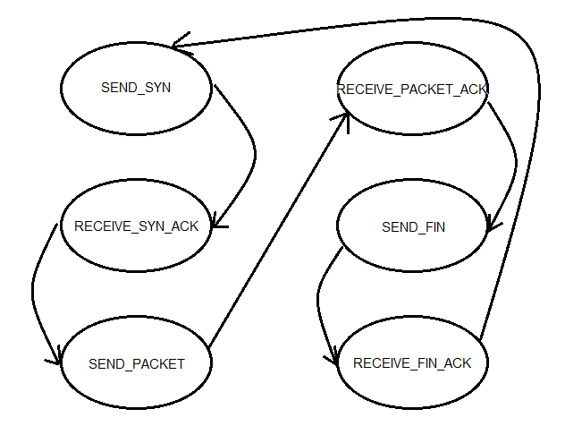
Figure 5: FSM for the sender.
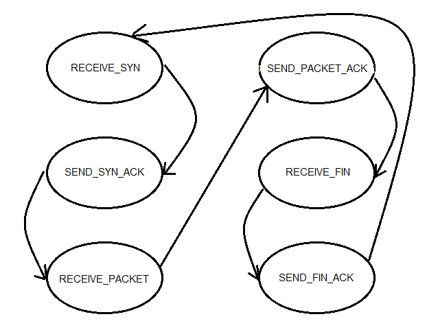
Figure 6: FSM for the receiver.
For our version of TCP/IP, we had three stages of delivery. In the first stage, we would initiate a three-way handshake, where the sender would send a SYN packet, the receiver would send both a SYN and an ACK of the SYN, and finally the sender would send an ACK of the SYN sent by the receiver. One difference between our protocol and the actual TCP/IP protocol is that we send some extra information in the first SYN request; namely, we tell the receiver how many data packets should be received before the entire MIDI file is sent. In the next stage, we begin sending packets of the MIDI stream. To ensure we encode and decode them in the proper order, we keep a packet ID variable, which tells us where it fits in the MIDI stream. Using a helper method write_to_tx(), which assembles a 64-byte payload based on the packet ID we are trying to send, the sender transmits the data along with the packet ID. On the other end, we receive this packet and place it in the proper spot based on the packet ID. If we receive it successfully, we send an ACK and increment the packet ID we are expecting to receive. If the sender receives an ACK, it will also increment the packet ID and send the next one. If the sender times out before it receives an ACK (we set the time-out to be 1 second), the send will attempt to send the same packet as before, without incrementing the packet ID. This system ensures that just one copy of every packet is sent and received. After the entire MIDI file is done transmitting, we send a FIN to signal that we are done sending. Similar to the SYN sequence, the receiver will send an ACK of the FIN back and exit the IR communication mode. When the sender receives this ACK, it will also exit the IR communication mode and we are done transmitting. If there are any dropped packets in this last transmission, we send the FIN/ACK several times to ensure that both MCUs leave this mode. Also note that we changed much of the implementation of IR communication from Lab 3 to serve our purposes. The code we were give transmitted strings, which used '\0' as a null-terminating character. For our purposes, that null-terminating character had significance for us; we could not simply stop transmission when we saw it. Therefore, we altered the code to transmit an array of chars, where '\0' was significant and not a special character. Because we could not indicate the end of a payload with a special character, all packets were of uniform payload size--unused payload bits were left unchanged. The receiver must know how many bits it is expecting in the payload beforehand. Thus, our communication is not as robust for general communication, but it serves our purposes because we know all SYNs and ACKs are one bit payloads, and all data payloads are 64 bits. Furthermore, we get the benefit of transmitting all possible characters. This software borrows from Professor Bruce Land's code (see "References").
Engine
The engine holds the main loop for the software's execution and the ISR that enables most of the commands' executions. Our DDS tables and MIDI tables are initialized, and all global flags are set to their initial values. Our Timer1 ISR does a lot of the heavy lifting in our code; it acts as a time base for MIDI files, calculates the sounds we should produce through FM synthesis and receives and sends characters during IR communication. Since we are not always recording MIDI files, producing notes or using IR communication, we used several flag variables to ensure we do not perform any unnecessary work in our ISR; we want to keep it as short as possible to ensure we miss no deadlines. When we are recording MIDI files, we add a quarter frame every 10 milliseconds to update our MIDI stream. When we are playing notes, we check which channels should be on, and for those channels, perform the FM synthesis calculations and change the value of OCR0A to produce the desired sounds. Lastly, when we are using our IR communication, it checks every millisecond if there is data to transmit or receive, and if there is, it performs the necessary actions. Our INT2 ISR returns execution to the CLI when the button wired to Pin B2 is pressed. Inside the ISR, all flags that keep execution in any one command's while loop are set low, so it breaks out and returns to the CLI.
"Bit Vector"
As explained in "USART Transmission" in our Hardware section, we chose to send 7 data bits and 2 stop bits per serial frame. Since our MIDI streams are indexed by byte arrays in memory, we could not simply iterate though the byte array and send one byte per frame. This library contains helper functions that ultimately allow "bit-indexing" of a byte array, meaning that you can get and set the ith bit in any byte array. get7() will return a byte comprised of the ith - i+6th bits in the array, and set7() will set the ith - i+6th bits in the array to an input byte (between 0x00 and 0x7f). Thus, we can decouple the 7-bit frame size from the 8-bit array indexing and elegantly disassemble our MIDI file into 7-bit frames, transmit them over the USART, and reassemble the 7-bit frames back into a byte array.
Unit Testing
Our software is very comprehensive and contains too many functions and libraries to trivially debug. Thus, we created a unit testing framework to ensure that nearly all of our functions behaved as expected with a variety of inputs. This gave us full confidence that our prototype would not produce any unintended software side-effects during use. We have included our unit tests with our source code on this webpage in hopes that future groups can use our testing framework and recognize the importance of creating unit tests for non-trivial software packages.
Results top
Overview
In the end, our project worked almost to specifications. We are able to play, record, merge and synthesize MIDI tracks on a single board, as well as send MIDI tracks through IR communication. We supported up to 16 customizable instrument sounds created using FM synthesis and could program any musical frequency for the eight buttons. Each MIDI track supported up for four simultaneous channels, each of which can have its own instrument and play three notes at the same time. We also implemented the teacher mode; there were two preprogrammed songs - "Rugrats Theme Song" and "Twinkle Twinkle Little Star" - which the user could play along with and receive feedback on how well the user did.
MIDI Synthesizer Timing Accuracy
The accuracy of the MIDI playback ensures that a played note turns on and off within 18 milliseconds of when it was actually played relative to time zero. Since our debouncing FSM's period is 4 milliseconds, and our FSM takes 2 transitions to verify a press or a release, this adds a latency of 8 milliseconds. Since all changes in the FSM are recorded every 10 milliseconds in our ISR, the worse case dictates that the actual note may be late in turning on or off by no more than 18 milliseconds.
DDS Frequency Accuracy
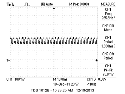
Figure 7 shows the accuracy of the DDS synthesizer for chosen output notes. We chose MIDI octave 4, since it is the default octave for the prototype and the most commonly used octave for our teaching algorithm. We also chose MIDI C6 to measure accuracy at higher frequencies. Note that these frequencies were taken after the DDS component had decayed to zero, so we can isolate the carrier frequency of the signal. We used an instrument with a sine wave base when taking these measurements. The actual waveforms taken from an oscilloscope are shown in Appendices.
| MIDI Note | Expected Frequency (Hz) | Actual Frequency (Hz) | Percent Error (%) |
|---|---|---|---|
| C4 | 261.63 | 267.4 | 2.21 |
| D4 | 293.67 | 293.9 | 0.08 |
| E4 | 329.63 | 337.1 | 2.27 |
| F4 | 349.23 | 349.7 | 0.13 |
| G4 | 392.00 | 385.8 | 1.58 |
| A4 | 440.00 | 437.3 | 0.61 |
| B4 | 493.88 | 500.0 | 1.24 |
| C6 | 1046.5 | 1000.8 | 4.37 |
Figure 7: DDS Synthesizer Note Accuracies
The percent error is no greater than about 2% for the most common notes. This error is detectable to trained musicians; however, the target audience of our product is novices, who should not detect this error. Possible sources of this error are the variable length of our DDS ISR (depending on the number of channels playing) and the design of our reconstruction filter.
Interference
Because we use IR light to transmit data, interference is always a possibility. In our prototypes, we used non-reflective material (black foam) to ensure that one prototype did not send IR signals to its own receiver. This issue proved problematic in testing our IR communication. The IR receiver may pick up other IR signals in the vicinity of use. Since our IR receiver expects a carrier frequency of 56 kHz, IR signals from common RC5 remotes should not interfere, since they have a carrier frequency of 36 kHz.
Safety
As stated earlier, our IR LEDs meet the standard presented by the IEC (EN DIN) 60825?1 SAFETY OF LASER PRODUCTS - Part 1 standard. Although our project uses standard Logitech PC speakers, which cannot be loud enough to cause hearing damage, our prototype can be hooked up to any viable speaker system. Thus, users are advised to operate well below 85 dB of output sound, which is the threshold above which hearing loss may occur. Our prototype contains many small objects: IR receivers, capacitors, IR LEDs and buttons. These may present choking hazards if removed from the prototype. Supervision is recommended for users of less than 5 years of age.
Usability
Our product is very easy to use: users can intuitively type the names of the commands they wish to execute. The push-button keyboard is arranged to mimic a standard piano keyboard, so there will be an easy learning curve for existing musicians, and it will allow new musicians to easily transition to a full-size keyboard. The only notable barrier to easy usability is ensuring the nonreflecting surface is in place to prevent a prototype from sending IR light to its own receiver. Users with special needs should be able to increase the size of the CLI on their Windows computer with Accessibility Options. Blind users may need assistance typing commands into the CLI, and deaf users may not be able to hear the musical output of the CLI.
Conclusions top
Final Thoughts
When we first conceptualized this project, we noted that many of the features we wanted to implement were not necessary for the core ability of this product, namely the ability to play and record melodies. In the end, we were able to implement all we set out to do, but faced many difficulties along the way. One of the biggest challenges we faced in implementing the MIDI library and IR communication was using bit operations and making sure they did exactly what we expected. There were many instances where a small edge case or lack of full understanding of bit manipulation methods (e.g. memcpy, strlen, etc.) caused seemingly nonsensical errors. In the future, we will read the C documentation more thoroughly before using its standard library. The only way we were able to complete both these functions was to build very modularly, having each function perform one small task and extensively unit test each function to ensure it performed to its specs. This project really taught us the value in unit testing and ensuring the pieces work before we build the entire product.
Conformance to Standards
We have conformed to all standards listed above: We followed the MIDI specification, and the only deviation is that our MIDI synthesizer plays it's own FM synthesis sounds instead of the default MIDI sounds. We also comply with international standard "IEC (EN DIN) 60825-1 SAFETY OF LASER PRODUCTS - Part 1 for our IR emitter.
Shortcomings
Although much of our project worked to specification, there are a couple aspects which are not robust. Our IR communication works well in the general case, but if the IR signals are too weak to detect properly, our FSMs can go out of sync and at this point, the IR communication will be stuck and need to be reset. Teacher mode also has a shortcoming: the grading algorithm performs poorly when we play many extra notes. Our detection method is much more tailored to mistimed notes and incorrect notes; we could have improved the algorithm to value all three errors the same. Another limitation we mentioned earlier is the maximum track length of 15 seconds. Since we did not implement DataFlash, we are unable to have full song length tracks, but rather only short melodies. For future extensions of this project, we hope to add DataFlash and enable much longer melodies to be recorded. Another limitation we faced was the maximum amount of notes we can play at one moment in time; although we support the ability to play three notes on each of four channels, if seven or more notes are played simultaneously, the pitch of the notes will drop. The reason for this drop is the fact that the ISR will miss its deadline, since we must perform FM synthesis on too many notes in the same ISR. The only way we can fix this issue is to have a faster clock, but this was not an option for our project. Lastly, we only hardcoded four different instruments for our device; we can easily create many more instruments, but did not have the time to experiment fully with FM synthesis sounds.
Intellectual Property Considerations
Our product is based on MIDI, which is a standard used by many products in our field and freely available on the internet. No licensing is necessary to use MIDI. The layout of our keyboard is based on the piano, which also has no copyright. The design of the IR transmitter is taken from Professor Bruce Land's ECE 4760 Lab 3. For software, we only used outside code provided to us by Bruce Land as a baseline for USART transmission, FM synthesis, IR transmission and DDS. We are free to use both his hardware and software for the project. As far as our own code, our MIDI implementation is likely more basic than existing ones on the market. Our teaching algorithm is also simple compared to more advanced engines used in popular games such as Guitar Hero or Rock Band. Thus, our project is unlikely to be considered for any patents. However, the combined application of these technologies is novel and likely conducive to a publishing opportunity. To date, we have been contacted by Circuit Cellar Magazine to submit an article outlining our prototype, and we will pursue other hardware and software periodicals for publishing opportunities.
Ethical Considerations
Throughout our project, we made sure to follow the IEEE Code of Ethics. We did not omit any details, and our project did not work with 100% accuracy all of the time. For a complete list of all known bugs, see the "Shortcomings" section. We made sure to do this because the IEEE Code of Ethics states that: "[Engineers should] be honest and realistic in stating claims or estimates based on available data." Additionally, we strived "to seek, accept, and offer honest criticism of technical work, to acknowledge and correct errors, and to credit properly the contributions of others." All of the sample code we used is properly cited below, and we credit our Professor Bruce Land with teaching us many of the necessary techniques we needed to complete this project. With regards to to "accept[ing] responsibility in making decisions consistent with the safety, health, and welfare of the public, and disclos[ing] promptly factors that might endanger the public or the environment," we made sure to outline the safety concerns posed by our prototype in our report and did not add any hardware or software that posed a risk to the public. Furthermore, we also attempted to "assist colleagues and co-workers in their professional development and to support them in following this code of ethics." We encouraged another group to go forward with their design earlier in the semester, and were always available to help our peers in lab.
Legal Considerations
The MIDI protocol we used is open-source and a standard for music files. The TCP/IP protocol we adapted is also open-source and has no legal considerations. Otherwise, we created all the code we used (using sample code from Prof. Land), did not infringe upon any intellectual property that we are aware of exists and have a safe product that does not pose any danger to anyone else. Since our transmitter broadcasts infrared energy rather than radio energy, it is not subject to FCC regulations.
Appendices top
A. Parts List and Costs
Note that this table reflects the quantities of parts required to make two prototypes, as we used two for our demo.
| Category | Item | Vendor | Unit Cost | Quantity | Total Cost |
|---|---|---|---|---|---|
| Electronics | White Board | ECE 4760 Lab | $6.00 | 2 | $12.00 |
| AtMega1284p Target Board | ECE 4760 Lab | $5.00 | 2 | $10.00 | |
| Logitech S-120 PC Multimedia Speakers | ECE 4760 Lab | $10.00 | 2 | $20.00 | |
| Power Supply | ECE 4760 Lab | $5.00 | 2 | $10.00 | |
| Solder Board (6 inch) | ECE 4760 Lab | $2.50 | 2 | $5.0 | |
| 12mm Round Pushbutton | ECE 4760 Lab | $0.35 | 16 | $5.60 | |
| Alligator Clips | ECE 4760 Lab | $0.50 | 2 | $1.00 | |
| USB Cable, Type A Male, Type B Male | ECE 4760 Lab | $4.00 | 2 | $8.00 | |
| TSOP34156 IR Receiver | ECE 4760 Lab | $1.20 | 2 | $2.40 | |
| TSAL6400 IR LED | ECE 4760 Lab | $0.55 | 4 | $2.20 | |
| 20 kΩ Resistor | ECE 4760 Lab | $0.00 | 2 | $0.00 | |
| 100 Ω Resistor | ECE 4760 Lab | $0.00 | 2 | $0.00 | |
| 500 kΩ Resistor | ECE 4760 Lab | $0.00 | 2 | $0.00 | |
| 330 kΩ Resistor | ECE 4760 Lab | $0.00 | 16 | $0.00 | |
| 10 nF Capacitor | ECE 4760 Lab | $0.00 | 2 | $0.00 | |
| 100 μF Electrolytic Capacitor | ECE 4760 Lab | $0.00 | 2 | $0.00 | |
| Total | $76.20 |
B. Source Code
| Name | Description |
|---|---|
| bit_vector.c | Helper methods for manipulating blocks of 7 bits in a byte array |
| bit_vector_test.c | Unit tests for bit_vector.c |
| dds.c | Code to create DDS sounds, handle button presses, and parse MIDI files |
| dds_test.c | Unit tests for dds.c |
| engine.c | Code for command line interface, main execution loop, sample song generation, and ISRs |
| ir_comm.c | Code for our IR transceiver and packet transmission algorithm |
| ir_comm_test.c | Unit tests for ir_comm.c |
| midi_lib.c | Code for reading, saving, and playing back MIDI files in real-time |
| midi_lib_test.c | Unit tests for midi_lib.c |
| teacher.c | Code for comparing the similarity of two MIDI streams for the teacher mode |
| teacher_test.c | Unit tests for teacher_test.c |
| uart.c | Code for PC UART connection |
| uart.h | Header file for PC UART connection |
C. Specific Task Breakdown
| Albert Liao | Matt Stern |
|---|---|
| TCP/IP Protocol and IR Communication | Designed engine.c Framework |
| FM Synthesis | MIDI Library |
| Soldering Keypads and Second MCU | Merging Tracks |
| PuTTY Interface | Direct Digital Synthesis |
| Completed Progress Updates and Parts Gathering | Teacher Mode |
| Unit Testing | Unit Testing |
| Software Debugging | Software Debugging |
D. Circuit Schematics
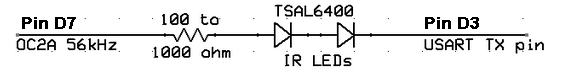
Appendix Figure 1: Circuit diagram of the IR LEDs.
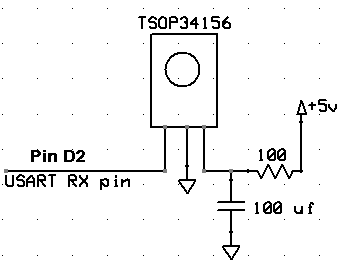
Appendix Figure 2: Circuit diagram of the IR receiver.
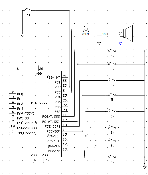
Appendix Figure 3: Circuit diagram of button board, reset button and output of the PWM.
E. Output Waveforms

Appendix Figure 4: MIDI C4 Waveform
Appendix Figure 5: MIDI D4 Waveform

Appendix Figure 6: MIDI E4 Waveform

Appendix Figure 7: MIDI F4 Waveform

Appendix Figure 8: MIDI G4 Waveform
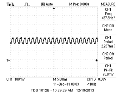
Appendix Figure 9: MIDI A4 Waveform

Appendix Figure 10: MIDI B4 Waveform
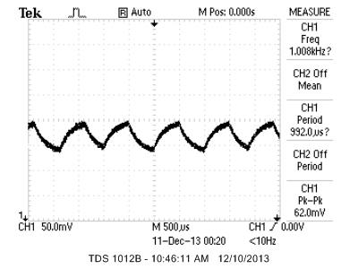
Appendix Figure 10: MIDI C6 Waveform
References top
This section provides links to external documents, code, and websites referenced and used throughout the project.
Datasheets
MIDI
FM Synthesis
IR Transceiver
Code References
Acknowledgements top
We'd like to thank our Professor Bruce Land for his guidance and help throughout the semester. We'd also like to thank our TAs for helping us work through tough bugs and giving us insightful advice.