Introduction top
"A new spin on Laser Tag with Wireless Real-Time Updates"
For our ECE 4760 final project, we designed and built our own laser tag system. We included many traditional laser tag features, but then added our own 4760 twist. For the purposes of a prototype for this class, we only created enough equipment for two players. This however could be easily scaled by building more blasters in the future. A demonstration of of our project may be viewed below:
High Level Design top
Motivation
Having both played standard laser tag games, we were interested in expanding the game beyond its traditional boundaries. The ultimate goal was to create a system which mirrored combat as close as possible and add new features that are normally only found in video games. We also felt laser tag would be cooler using real lasers, as opposed to using infrared light as in all commercially available systems. With this in mind, we started with the essential components, namely the laser and detector system, and expanded the game by adding an LCD screen and RF transceiver to provide score updates and configurability.
Overview
At the highest level, our system has three major components. These are the laser blaster, base station, and shot detection vest. A block diagram is shown below to depict how all of these components are interconnected.
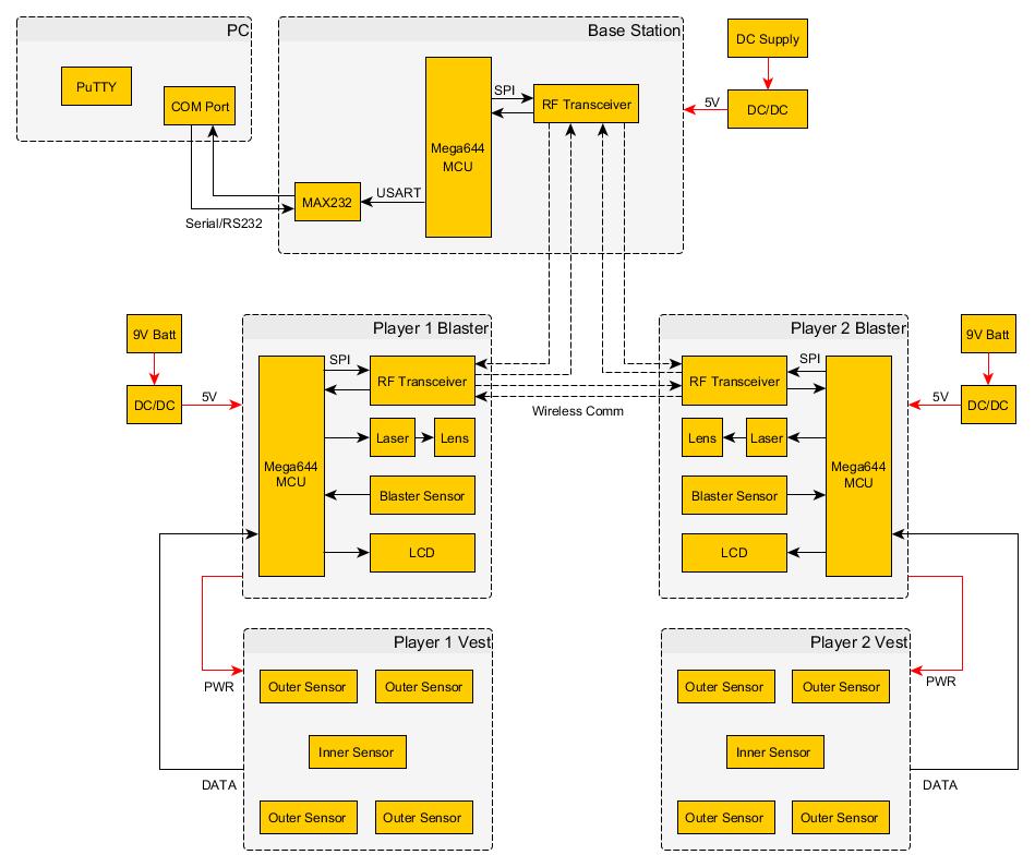
A High Level Block Diagram of our Laser Tag System
Each player's vest is instrumented with sensors to detect shots coming from other players. Each blaster has an RF transceiver, an LCD, a sensor, and a laser. The laser is used to fire at other players, and is only turned on when the player presses their fire button. The RF transceiver allows each player to send and receive real-time information about the game. This information, such as player health, is displayed on the blaster's LCD. Finally, each blaster is equipped with a sensor to determine if the blaster itself has been hit by another player. The final component, which is the base station, connects to a computer via a serial connection. The base station serves as a relay point for the real-time updates, and logs the game activity. It also sets the game parameters, such as starting health and ammo, and then begins the game.
How to Play the Game
Each blaster has four buttons that control its actions. The first button fires the laser on the blaster. The second button reloads the blaster, replenishing the ammo count. The third button cycles through LCD views, and the fourth button switches weapon types. The user interface can be seen below:
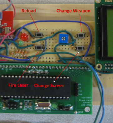
A Summary of the Blaster User Interface
The LCD has three different views, these are self-info, scoreboard, and weapon type. The user has the ability to scroll between these screens by pressing the change screen button. On the self-info screen, the player can view his or her own health and ammo count. By looking at the scoreboard, the player can see the health of all of the players in the game. The weapon screen tells the player if they are in single shot or automatic mode.
The objective of the game is to be the last man standing. Players can create their own custom games with their own parameters, or choose default values. Default values assign players with 100 health points, 100 rounds of ammunition for the automatic blaster, and unlimited ammunition for the pistol blaster. However, each pistol clip has only 10 shots, so the player will need to reload. When a player is hit on their vest, points are deducted from their total health. If hit in the inner ring of the vest, 10 points are deducted. If hit in the outer ring instead, only 5 points are deducted. Hitting a player on their blaster sensor will prevent them from shooting for the next five seconds and will also deduct five health.
Hardware/Software Tradeoffs
Phototransistors vs. Solar Panel
Originally, we tried using a solar panel as the sensor system. In its traditional use, current is induced on the panel when hit with sunlight, providing power to a system. We felt we could trigger the same effect with a laser flash. The panel provides a continuous surface across which the player could shoot at, and seemed like a cleaner design that having to attach many small phototransistors to a vest. However, the changes in current caused by fluctuations in ambient light relative to changes as a result of the incident laser is so large that it would be impossible to detect a laser blast by using the panel. The problem of having a continuous surface was solved by placing the phototransistors close enough together, eliminating any blind spots.
Broadcast vs. Point-to-Point Communication
The RF transceivers offer a mode which enables the receiver to automatically send back acknowledgement packets to the sender, making it easy to implement reliable point-to-point communication. Using this mode would allow the original sender to be sure that its packet reaches each destination point. However, point-to-point communication requires the sender to enter a full conversation with each receiver. This makes the software much more complicated, especially as the number of players grows. Sending out a broadcast signal that might not always reach its destination is still reliable provided the signal is broadcast enough times. Also, missed updates are acceptable since play can continue without an up-to-date scoreboard. After switching to a broadcast approach, we also realized that blasters could just as easily send updates to each other, even further simplifying the software and expanding the range of play, as discussed in the results below.
Standards
To enable communication between the PC, via PuTTy, and the base station, we serialized data according to the UART standard. An additional IC connecting the serial port to the microcontroller implemented the RS-232 standard, which sets standards on pin configurations, as well as electrical and timing characteristics. We found UART useful and straightforward for both printing out status updates and for accepting user input upon startup, and most importantly for printing out status updates during debug. The RF transceiver and microcontroller communicate using the Serial Peripheral Interface (SPI) bus, an implementation that already existed in the drivers that we selected. The laser conforms to the ANSI Z136 class IIIA specifications: output power does not exceed 5 mW and beam power density may not exceed 2.5 mW/cm2. Our laser tag system is considered a Digital Device under FCC regulations for RF equipment since it is a small electronic device to be used in a residential environment by the general public. It operates at 2.4 GHz, an allowable frequency for such devices.
Intellectual Property
Our project does not infringe on the intellectual proprty or patents of others. All commercially available laser tag systems use infrared light as opposed to actual lasers, a major difference between the systems. The laser tag concept itself is not owned and many different variations exist in the market.
Hardware top
Overview
The hardware can be grouped into three categories: voltage regulation, shot detection, and microcontroller processing and peripherals. Both the blasters and base station have voltage regulation and processing/peripheral blocks, but the base station does not have a shot detection block.
Voltage Regulation
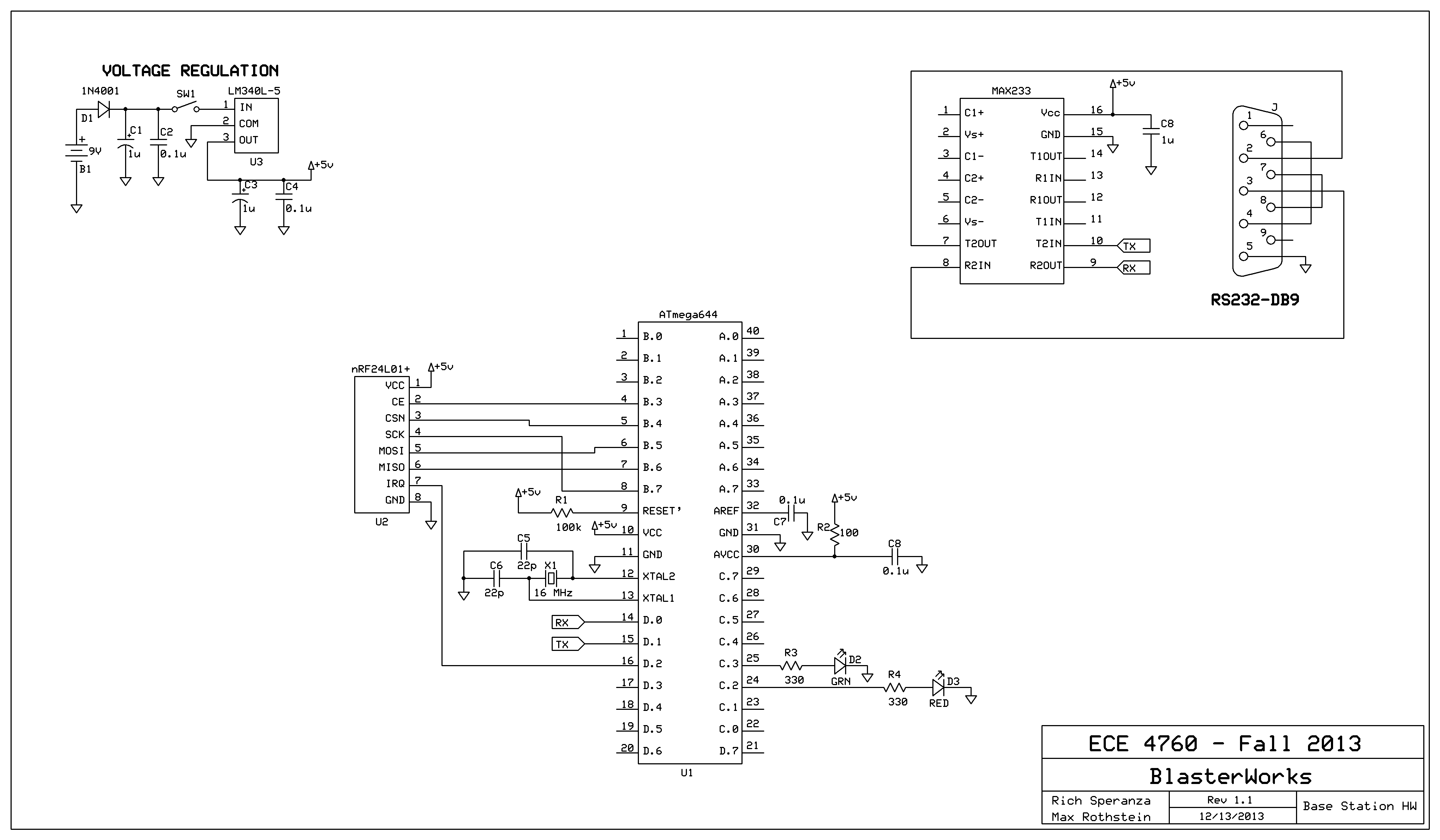
The pupose of the voltage regulation block is to convert a relatively high voltage into a lower voltage that can power the microcontroller and its peripherals. In the blaster’s case, the power source is a 9V battery. For the base station, a 12V DC power supply is used. Regardless, the voltage regulation stage takes this power as its input and outputs a 5V DC signal.
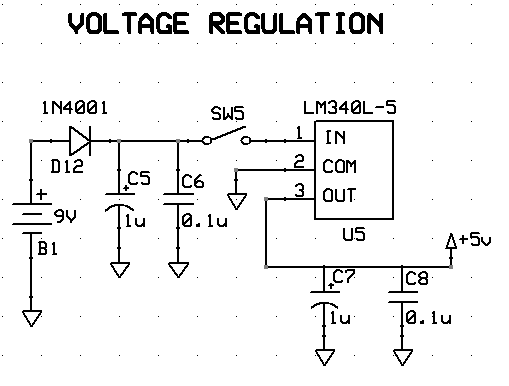
Schematic of the Voltage Regulation Block
This stage is relatively simple and contains only a few components. B1 in the diagram models the power source, which is either a 9V battery or a DC power supply. This feeds into a 1N4001 diode, whose purpose is protect our circuit from being damaged should power be connected backwards. When the positive and negative leads are connected correctly, the diode allows power to flow through the circuit. When the terminals are connected backwards, the diode is reverse biased, preventing any damage to other components. A power switch between the voltage regulator and the diode allows us to easily turn our device on and off. Finally, we have a LM340L-5 voltage regulator. This component takes the high voltage in and outputs a steady 5V signal. The two capacitors simply filter out noise that might be riding on top of this signal. The 0.1uF ceramic capacitor is small and has the ability to filter out fast transients. Although the small ceramic capacitor is fast, it lacks capacity. The slow 1uF electrolytic capacitor complements the speed of the smaller capacitor with its larger capacity.
Shot Detection
The shot detection block’s mission is catch any lasers that are shot at the user and to also give information to the microcontroller that can determine where the user was hit.
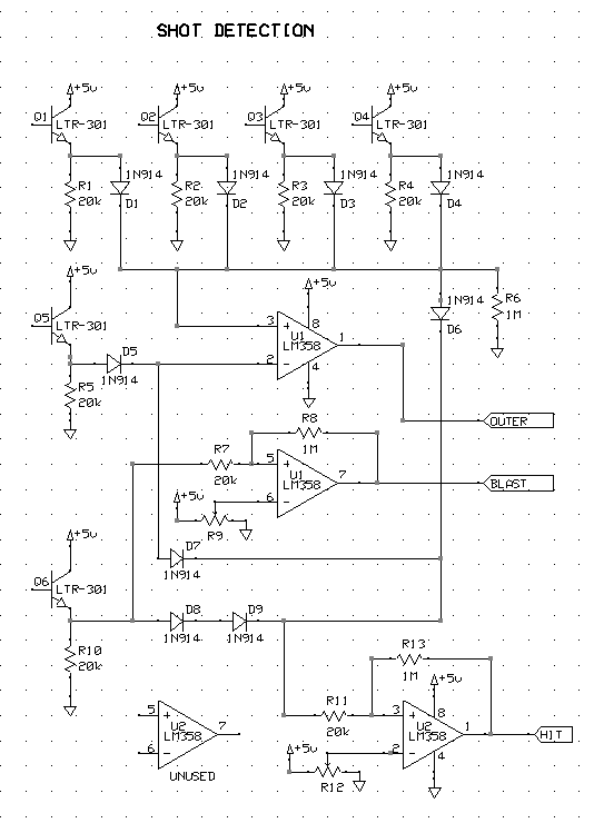
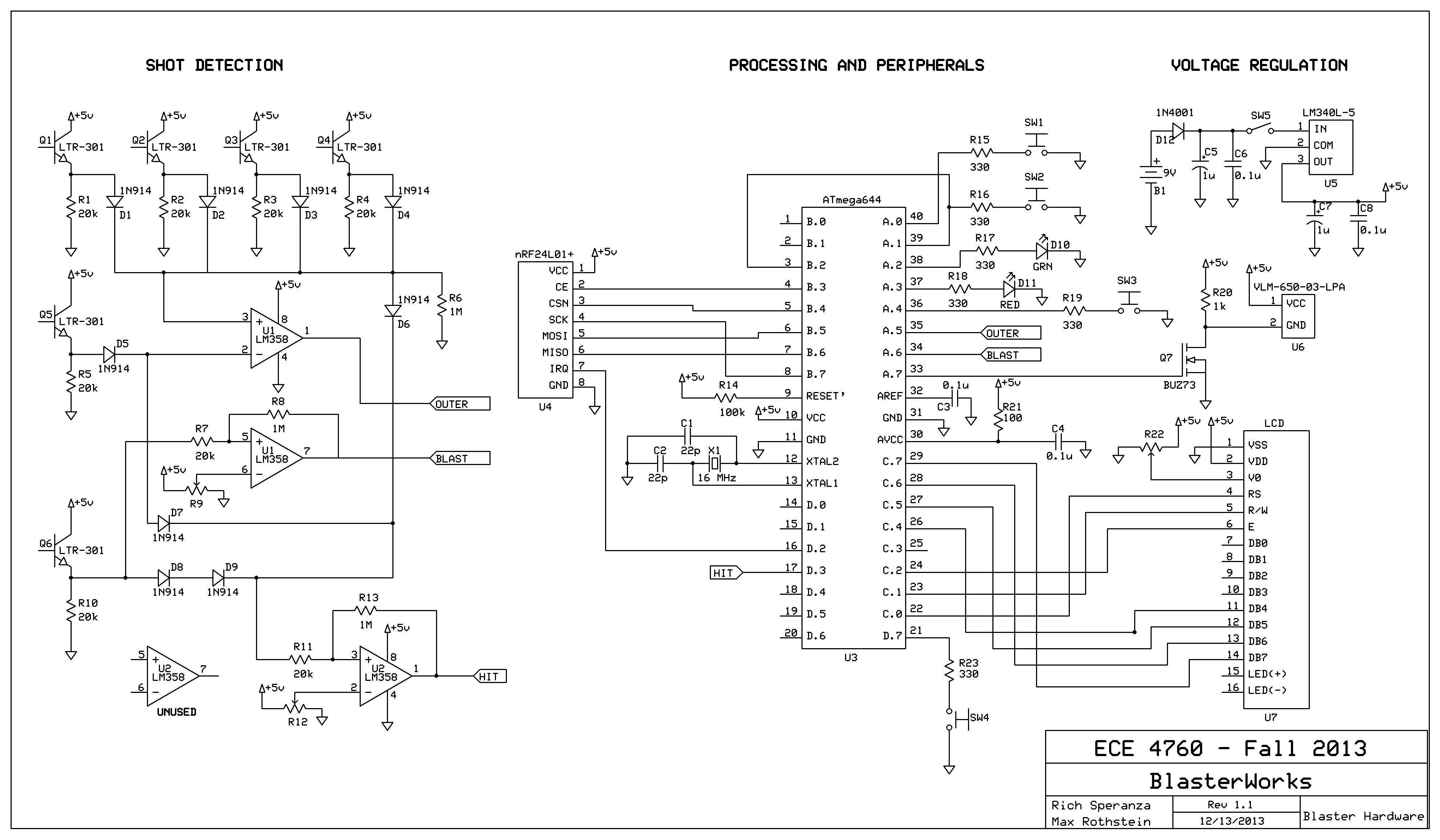
Schematic of the Shot Detection Block
By looking at the schematic, we can see that there are a total of six LTR-301 phototransistors. Q1-Q4 on the schematic correspond to the four outer detectors on the user’s chest plate. Q5 is the sensor for the inner detector on the chest plate. Finally, Q6 is the last sensor which is placed on the user’s blaster. These sensors can be thought of as a normal BJT, however, instead of biasing the base manually, the laser does the work for us. Without any light shining on the base of the phototransistor, the device is turned off and there is an effective open between the collector and emitter. As light hits the component, the BJT begins to turn on, allowing the 5V from the collector flow to the emitter. Something worth noting is that this device is not an “all or nothing” device. The voltage at the emitter is not always either 0V or 5V. Depending on how hard the component is hit by light, the device may only be partially on. This behavior is the reason why comparators are needed.
The purpose of the fast switching diodes (D1-D9) in the circuit is to create a logic “OR” function. Regardless of which sensor is hit, we want a comparator to flip to throw an external interrupt on the microcontroller. By using an OR circuit, we can obtain this functionality. A diode OR circuit allows the highest voltage in the OR to pass through, then back-biases the remaining diodes.
The LM358 operational amplifiers (op-amps) in our circuits are used as comparators and Schmitt triggers to send effective “bits” to our microcontroller. The bottom op-amp is configured as a Schmitt trigger. This is essentially a comparator with hysteresis. A 10k potentiometer sets a reference level at which the Schmitt trigger flips. If a shot is detected from any of the six sensors, then the voltage at the non-inverting input raises above the set threshold voltage. Due to positive feedback, the output of the Schmitt trigger is driven high, which causes an external interrupt on INT0.
The LM358 package conveniently has two op-amps inside of it. On the top LM358, the first op-amp is configured as a simple comparator. It makes a comparison between the inner sensor and four outer sensors. By making this comparison, we can effectively tell if the user was hit closer to the inner sensor or closer to the outer sensors. The 1M resistors on each network pulls voltage through the first layer of diodes even if the second layer is biased off. The second op-amp in the package is configured as a Schmitt trigger, similar to the shot comparator. This Schmitt trigger is attached to the sensor that is placed on the blaster. A reference voltage is set with a 10k potentiometer on the inverting input. When the user is shot on the blaster, the non-inverting input goes above this threshold and causes the output of the op-amp to flip. Whenever the bottom op-amp flips and generates an external interrupt, the two bits from the top LM358 are read. The functionality of our logic is summarized in following table:
| Outer Bit | Blast Bit | Desired Function |
|---|---|---|
| 0 | 0 | Inner Hit - Subtract 10 Health |
| 0 | 1 | Blaster is Hit - Prevent Firing and Subtract 5 Health |
| 1 | 0 | Outer Hit - Subtract 5 Health |
| 1 | 1 | Blaster Hit - Prevent Firing and Subtract 5 Health |
Processing and Peripherals
This is the final hardware stage in our design. This stage includes all of the remaining circuitry that interface with the microcontroller to give us our desired functionality. We will divide this section into each of the peripherals attached to the microcontroller.
Microcontroller Upkeep
This portion contains all of the filtering capacitors and resistors needed in order to get the microcontroller running. While these components are not necessarily a peripheral, it is worth including should someone want to recreate our project.
On pin 9 of the microcontroller, there is a 1k resistor that is tied to VCC. This is a pull-up resistor. Since the reset pin on the MCU is active low, we want this pin to be VCC under normal operation.
Pins 12 and 13 of the microcontroller handle the use of an external oscillator. For our project, we use a 16 MHz crystal as our main clock. There are two 22 pF capacitors wrapped around the crystal to provide some filtering on the pins.
On pin 32, there is a connection to ground through a 0.1uF capacitor. This provides some filtering on the AREF pin.
Finally, on pin 30, there is a connection to ground through a 0.1uF capacitor, but also a connection to VCC through a 100 ohm resistor. This pulls the AREF pin up and provides some filtering.
Laser Driver
A special circuit is needed in order to drive the laser on each blaster. The ATmega644 I/O pins (and microcontroller I/O pins in general) have a limited amount of current that they can source. In order to drive the laser hard enough for it to be usable, a buffer is needed.
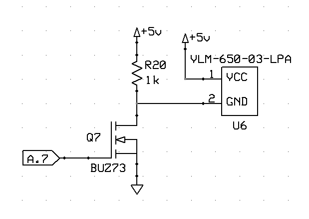
Schematic of the Laser Driver
For our application, a MOSFET is used to buffer the current needed to drive our laser. The source of the MOSFET is tied directly to ground and the drain is connected to VCC through a 1k resistor. The gate of the MOSFET is driven by the microcontroller’s A.7 pin. Finally, the laser is connected to VCC and the MOSFET drain. When the output on A.7 is low, the MOSFET is off, leaving the laser off. When the MOSFET gate is driven high, the device turns on, effectively connecting the negative terminal of the laser to ground. This functionality provides the laser with the current it needs, giving us maximum distance.
Spreading Lens
The sensor system as described would detect laser beams directly incident on the phototransistors very well, but would not be able to detect shots pointed close by. At a distance of 5 meters, the spot size is approximately 6mm in diameter. By adding a concave lens in front of the beam, the diameter grows to a much larger size a few meters away, allowing us to only use a few phototransistors, rather than potentially hundreds, to capture a shot.
We used foam core from a local crafts store to house the lens/laser system, and it worked quite effectively. They were both placed in the foam by making a small entry cut, and then firmly pressing the object down through the foam. Then, we peeled away the foam covering the glass portion of the lens.
LED Driving
LEDs in our circuit are driven directly from a microcontroller I/O port. Since LEDs only require about 20mA of current, the MCU is able to provide enough current to light up the LED. In order to set the current through the LED, a current-limiting resistor is used. We use a 330 ohm resistor in our design. Using Ohm’s law, we can estimate the current flowing through each LED.
V=IR
The forward voltage drop over a green LED is typically 2.1V. This means that 2.9V of the 5V signal are left to drop over the current-limiting resistor.
(2.9 V)/(330 Ω)=8.79 mA
For a red LED, the forward voltage drop is less, typically around 1.8V. This means that 3.2V of the original 5V are left to drop over the current-limiting resistor.
(1.8 V)/(330 V)=5.45 mA
In both cases, current is kept well below the maximum 20 mA specification, while still providing enough current to brightly light the LEDs.
Buttons
There are four buttons in our design which are used perform different functions with the blaster. The functions are fire, reload, change screen, and change weapon. The buttons are connected to ground though a current-limiting resistor. Since the microcontroller I/O pins are set to pull-up mode, when a button is pushed, the signal will switch to low. By reading this, we can determine if the user is trying to shoot the blaster, etc.
Liquid Crystal Display (LCD)
The LCD is a small 8 character screen with two rows. This screen provides feedback to user with different information. The user has the ability to flip through different screens by pressing a button. He or she also has the ability to use a button to select a different weapon during the game. The LCD screen is connected as follows:
| LCD Connection | Microcontroller Connection |
|---|---|
| 1 - VSS | 11 - GND |
| 2 - VDD | 10 - VCC |
| 3 - V0 | Potentiometer middle |
| 4 - RS | 22 - C.0 |
| 5 - R/W | 23 - C.1 |
| 6 - E | 24 - C.2 |
| 7 - DB0 | No Connect |
| 8 - DB1 | No Connect |
| 9 - DB2 | No Connect |
| 10 - DB3 | No Connect |
| 11 - DB4 | 26 - C.4 |
| 12 - DB5 | 27 - C.5 |
| 13 - DB6 | 28 - C.6 |
| 14 - DB7 | 29 - C.7 |
| 15 - LED(+) | No Connect |
| 16 - LED(-) | No Connect |
Wireless Radio
The final peripheral in our system is the Nordic nRF24L01+ transceiver, a 2.4 GHz wireless radio module. We have a wireless module on both blasters and the base station. This module is what gives us the ability to update each player with information about the game. The pinout between the radio and microcontroller is as follows:
| Wireless Radio Connection | Microcontroller Connection |
|---|---|
| 1 - VCC | 10 - VCC |
| 2 - CE | 4 - B.3 |
| 3 - CSN | 5 - B.4 |
| 4 - SCK | 8 - B.7 |
| 5 - MOSI | 6 - B.5 |
| 6 - MISO | 7 - B.6 |
| 7 - IRQ | 16 - D.2 |
| 8 - GND | 11 - GND |
Software top
Overview
The high level software design can be divided into the same general categories as the hardware, as it serves to coordinate concurrent operation of the wireless communication, the LCD screen, response to the shot detection, firing the blaster, and the various buttons. Two separate c files are needed, base_station.c, which controls the base station, and blaster.c, which controls both blasters. Each blaster is also provided with a unique identifier, my_number, when programmed.
These activities are managed by the Tiny Real Time (TRT) kernel. The kernel allows us to easily manage the main tasks and control how often to run them, as well as to provide certain tasks with a higher priority when needed. Additionally, the LCD update is a slow process and might otherwise create a bottleneck on our system. By scheduling other tasks at the same time as the LCD update, the controller is able to continuously accomplish work. The four tasks are and task_health(), task_wireless(), task_lcd_update(), and task_laser(). Additionally, external interrupts are used to handle shot detection and firing the blaster.
task_health() and Shot Detection ISR
Shot detection is performed by an Interrupt Service Routine (ISR) by using an external interrupt on PinD.3, which is connected to the output of the shot detection comparator. When the interrupt is triggered, the ISR reads two other bits of information from the shot detection hardware. A blaster shot is detected by reading the value of PinA.5, and a shot to the outer ring of phototransistors on the detector is detected by reading the value of PinA.6. Shots to the blaster and outer ring are flagged as a weak_hit, while an inner shot is flagged as a strong_hit. In task_health(), the values of those two variables are checked and the corresponding health update is made. To limit the number of hits allowed per a given amount of time, the task sleeps for a longer period of time after detecting a hit. As in traditional laser tag, this allows a player who has been shot to retreat and reset after getting shot. Also, it prevents small hardware oscillations from affecting the software operation.
task_wireless()
The wireless communication allows us to provide the players with real time information on the state of the game, providing health information for the other players. Additionally, it provides a way to configure the game from the base station terminal on startup, and send an alert when the game has finished.
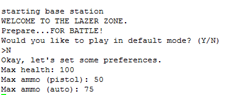
The wireless communications are handled by a state machine, which allows a back and forth conversation between all blasters and the base station. While the base station and blaster have slightly different behaviors, the state machine is almost identical from a high level. The main difference is during initialization state, which is called INIT_GAME for both. In the blaster’s initialization state, it waits on a packet containing the game configurations, namely maximum health and ammo, while blinking the red LED. This packet has a special identifier to indicate it is an initialization packet, rather than an update packet. In the base station’s initialization state, it first prompts the user via the PuTTy terminal to respond to a series of questions regarding game configurations. Once these questions have been answered, the base station sends packets to the awaiting blasters. To ensure delivery without acknowledgement, the base station transmits this message for a couple of seconds before transitioning to the next state. Once a blaster is initialized, the green LED turns on and it transitions to the next state, INIT_RX.
In INIT_RX, the wireless module is set to receiver mode, and then the controller transitions immediately to POLL_UPDATE. Here, the controller continuously checks to see if a new packet is available in the receive FIFO. That packet will contain the remaining hit points and ammo for all players. Essentially, this allows any player/base station to update any player/base station on the current state of the game. For example, Player 1 could send an update packet to Player 2, Player 2 then updates its local information and sends its own update packet that the base station might receive. This extends the range of play for the game because players are not required to be in range of the base station at all times. In order to reconcile potential differences between those update packets, a value is only considered new if it is less than the local value. This preserves the proper state because health and total ammo can only decrease over time.
If the base station receives an update, it transitions to INIT_TX, where the mode of the transceiver is changed to transmit. The blaster only transitions to INIT_TX when the player is shot, which is detected by an external interrupt as discussed earlier. Both transition immediately to SEND_UPDATE after the initialization is complete. Here, the update packet is formatted and broadcast out. To simplify the communication, the message is transmitted continuously while blinking the green LED for a set duration without requesting a receive packet acknowledgement. This allows the base station to reach all blasters without needing to spend time performing a hand shake with each player. For the purposes of the game, it is acceptable if any one controller misses an update. After the update is sent, both switch back to receive mode and wait on new updates.
task_lcd_update()
The LCD screen can either display personal status info, i.e. its local health and ammo values, the current blaster type, or the scoreboard containing the global health values. The state is controlled by clicking the “Change Screen” button. This results in incrementing the state variable to the next possible screen. In order to prevent the screen from flashing, it is only updated when new information is available. Since updating the LCD is a relatively slow process, local copies of the game info are created and displayed, which means the display may lag behind the true values. The difference will only be on the order a few milliseconds, so it will not affect the game play. This task also handles reload, which is done by polling PinA.1, which is driven low by pushing the “Reload” button.
task_laser() and Shot Fired Interrupt Service Routine
This task implements the two types of blasters available to each player: automatic and single shot. Each player starts out using their automatic blaster, and may choose to switch between weapon types by clicking the “Change Weapon” button.
When using the automatic blaster, the player only needs to hold down the “Fire Laser” button and the laser will continuously fire. On alternate passes through this portion of the loop, the output pin driving the laser is turned on and off, its rate controlled by the TRT kernel function trtSleepUntil(). The player’s ammo value is decremented on each fire.
When using single shot, the trigger detection makes user of an external interrupt. The “Fire Laser” button is also wired to INT2 on PinB.2, which is triggered by a transition from high to low. A flag, called trigger_interrupt, is set in the ISR for the external interrupt. The value of the flag is read within the task and a shot is fired as a result. Button clicks reliably result in only one laser fire since the allowed time between shots, which is controlled by the sleep time, is long enough for any transient signals to die out. If the blaster is disabled as a result of getting shot directly in the blaster, then the task sleeps for five seconds, rendering the blaster unusable.
Challenges
The main challenge was enabling wireless communication. Code for the drivers was borrowed from a previous project (see Acknowledgements); however, the sample code does not implement a system in which one controller takes on the role of both transmitter and receiver. The function set_mode() is provided in wireless.c to change between modes, but this function alone does not work. In order to switch between modes, we discovered it was necessary to clear out the receiver buffer by calling flush_RX_FIFO(), and then setting the new mode. The transceiver does not maintain the transmitter address while in receive mode, so we needed to call set_TX_addr() with the new address when switching from receiver to transmitter mode.
Results top
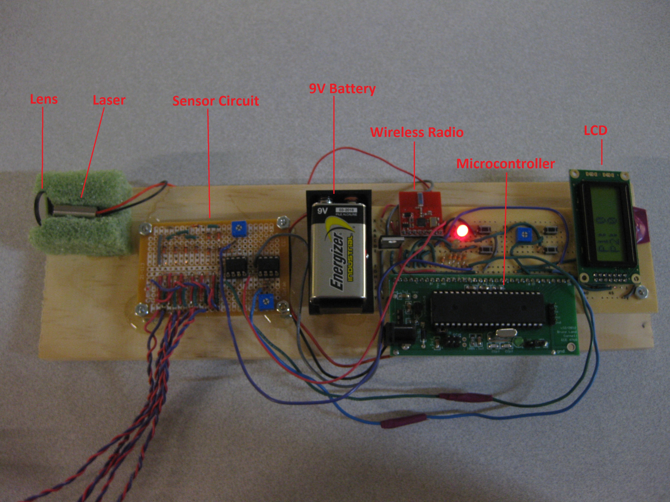
We successfully created working prototypes for one base station and two blasters, each equipped with a sensor vest.
Usability
The blaster circuit boards, along with the laser module, are mounted on wood, providing a sturdy build and making them easy to hold and operate. However, the many long wires extending from the blaster to the sensor vest are not ideal for the design, as they often block other laser shots, and simply get in the way when trying to operate the blaster. A different wire type paired with proper connectors would be used in a production design to solve these problems.
Range and Reliability
The limiting factor for the range of the game is the laser module and sensor system. The sensor vest can detect shots from a maximum range of approximately 5 meters. The short range is due to both decreased intensity as well as the sensitivity of the sensor system. More precise tuning of the comparator’s hysteresis as well as noise reduction from ambient light would help to improve the range of the system. Additionally, a production model with an additional focusing convex lens would have greater range, since the beam’s power density would not drop off as quickly.
At a range of 3 meters, our system is approximately 92% reliable in logging hits. This test was carried out by first fixing the direction of the blaster to point directly at the center of one phototransistor on the vest, and then firing repeatedly while holding the vest steady. Most importantly, no false positives were detected while playing in a well lit room.
The range of the wireless transceivers in open lab space is approximately 32 meters. Due to the method of sending updates, in which the transmitter sends out packets continuously for a couple of seconds, packets are reliably received while in range. As long as the players stay within 32 meters of each other the game can continue, regardless of how far they are away from the base station, since the blasters can maintain communications with each other.
The battery life of the blasters is sufficient for a number of games. At steady state, a blaster draws about 34mA, and jumps to about 64mA when firing the blaster. In the worst case scenario, the blaster can fire for 50% of the time, putting the average current draw at 49mA. This translates to a lifetime of 12.8 hours based off of a 625mAH lifetime of the 9V battery. However, a more reasonable estimation is that the blaster is firing about 5% of the time, resulting in a average current draw of 35.5mA, and a 17.6 hour lifetime.
Interference
Our wireless system runs at 2.4GHz and could interfere with other wireless transceivers running at the same frequency. However, our wireless transceivers will throw away packets that do not have the correct identification numbers, meaning that only the correct packets will be stored and processed. Also, no other groups present were using the same wireless transceivers during our demonstration.
Safety
The main safety concern is the use of a Class IIIA laser, which can cause retinal damage if pointed directly at the eye for more than two minutes. However, the duration of a single shot is only 0.5 seconds, well below the necessary exposure time that would cause damage. Also, the concave lens placed in front of the laser module spreads out the beam, greatly reducing the power density of the beam, rendering it virtually harmless.
Final Blaster Prototype
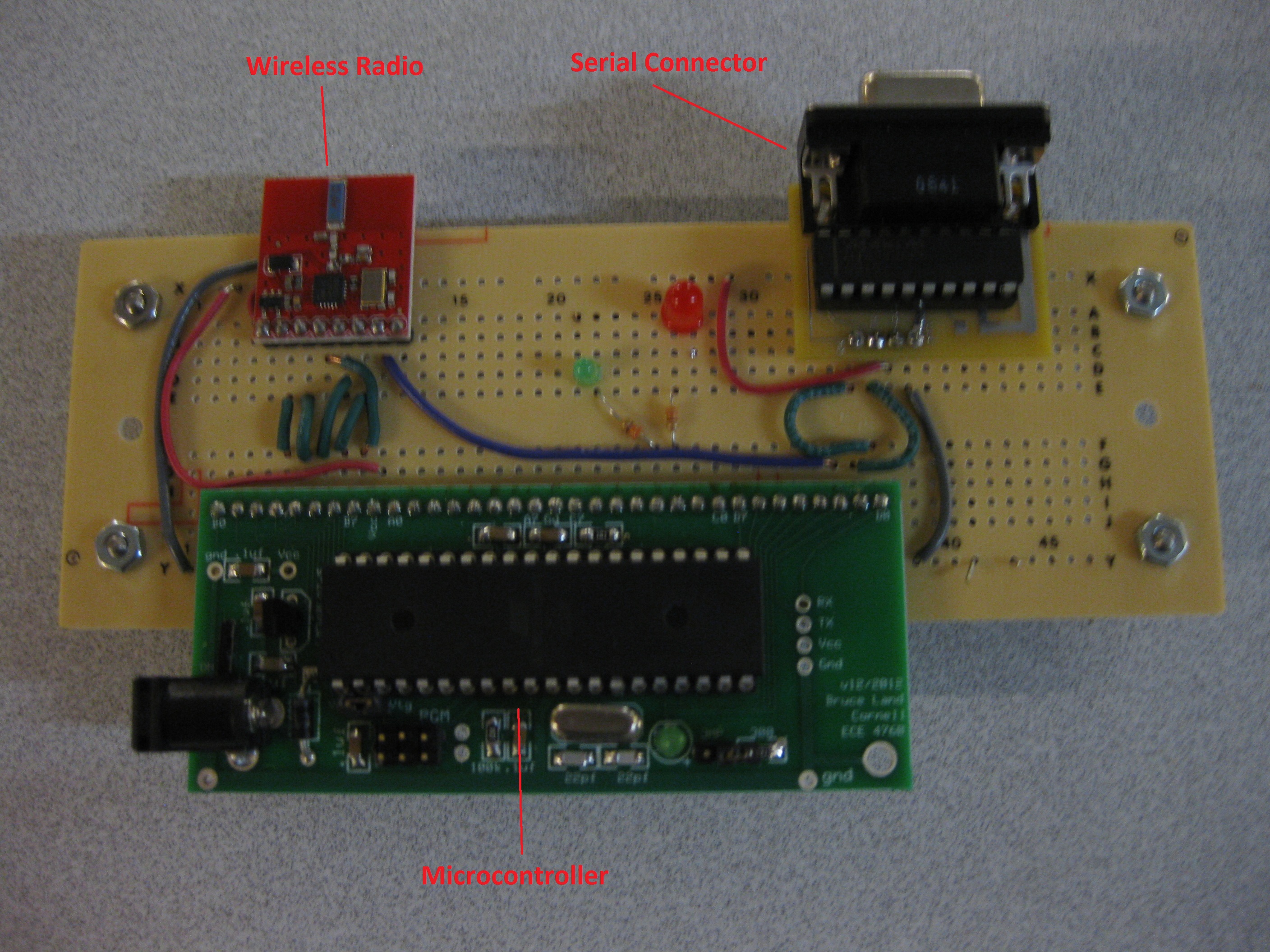
Final Base Station Prototype
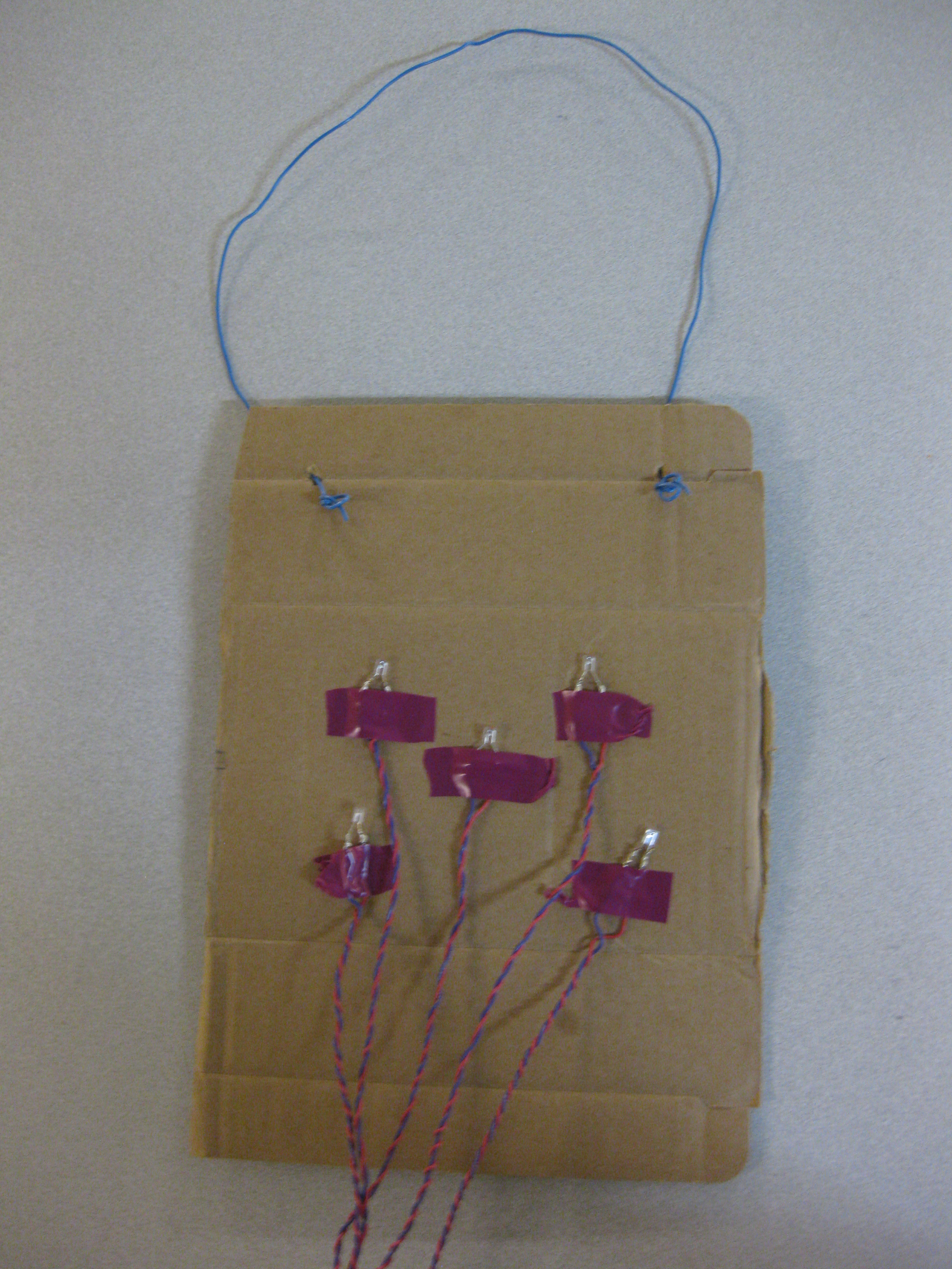
Final Sensor Vest Prototype
User Interface Screenshot
Conclusions top
Summary
We achieved the main goals as originally outlined in our proposal, and created a working prototype design that could actually be used to play a game of laser tag. We borrowed lessons learned from all of the previous labs in ECE 4760, learned some new ones, and successfully integrated them into a single product. Given the chance to do this project again, we would have taken into consideration the complexity of integrating many working parts and given ourselves more time for this portion, rather than assuming that they would simply “work” when they were all put together. Originally, we wanted to also have sound effects to make exciting “laser blasting” sounds, but time limitations prevented us from finishing the task. In the future, not only would we like to add sound back in, but we would also like to build more blasters to allow many more players. Also, the lasers could be fired with a payload that would allow the detector to determine the originator of the shot. Perhaps most importantly, expanded range would make the game much more interesting to play. We see plenty of opportunity to take our core system and create an exciting and unique laser tag game.
Intellectual Property Considerations
We do not anticipate patenting this work at this time, and are releasing our code. Many patents exist that describe a general light operated or infrared light operated shooting game, such as Electronic game with separate emitter (US 5672108 A) and Lazer tag advanced (US 7846028 B2). However, we did not find any games that use actual lasers. Also, our system expands upon others with the special “bullseye” type target, wireless communication, and LCD display.
Legal Considerations
Our Radio Frequency transceiver complies with FCC regulations and does not require any special permission due to its classification as a household digital device and its operating frequency of 2.4 GHz.
Ethical Considerations
Throughout our project we did our best to comply with the IEEE Code of Ethics. While creating the final prototype and assembling the electrical parts, we were sure the follow safety guidelines as outlined in lab, such as wearing goggles at all times while soldering. Lasers were handled with care and never pointed at other working groups or ourselves, and the spreading lens was added early to make them safer to work with in a lab environment. Any work or ideas borrowed from previous projects was done with permission and acknowledged when necessary, and no work conflicted with current projects. While we started with a well known idea, we used information learned in class to expand on the simple concept and make an interesting new product. We were honest and accurate with reporting the results and reliability of our system.
Appendices top
A. Parts List and Costs
In total, our parts cost came out to $96.76. This cost includes the development of two laser tag blasters and a base station. A detailed parts list is shown below:
| Category | Part | Vendor | Part Number | Cost | Quantity | Total Cost |
|---|---|---|---|---|---|---|
| Blaster | ||||||
| Shot Detection | Phototransistor | Digikey | LTR-301 | $0.33 | 6 | $1.98 |
| Fast Switching Diode | 4760 Lab | 1N914 | $0.1 | 9 | $0.9 | |
| Op-Amp IC | 4760 Lab | LM358P | $0 | 2 | $0 | |
| 8-Pin DIP Socket | 4760 Lab | $0.5 | 2 | $1 | ||
| 20kOhm Resistor | 4760 Lab | $0 | 8 | $0 | ||
| 1MOhm Resistor | 4760 Lab | $0 | 2 | $3 | ||
| 10kOhm Potentiometer | 4760 Lab | $0 | 2 | $0 | ||
| 2" Solder Board | 4760 Lab | $1 | 2 | $2 | ||
| Core | 9V Battery | Digikey | EN22 | $2 | 1 | $2 |
| 9V Harness | Digikey | BH9VW | $1.51 | 1 | $1.51 | |
| 1uF Capacitor | 4760 Lab | $0 | 2 | $0 | ||
| 0.1uF Capacitor | 4760 Lab | $0 | 2 | $0 | ||
| Microcontroller | 4760 Lab | ATmega644 | $2 | 1 | $2 | |
| Custom PC Board | 4760 Lab | $4 | 1 | $4 | ||
| Peripherals | 650nm Class IIIA Laser Module | Digikey | VLM-650-03-LPA | $13.18 | 1 | $13.18 |
| Dual-Concave Lens | Surplus Shed | L5315 | $4.00 | 1 | $4.00 | |
| MOSFET | 4760 Lab | BUZ73AH | $1.26 | 1 | $1.26 | |
| 1kOhm Resistor | 4760 Lab | $0.00 | 1 | $0.00 | ||
| 330Ohm Resistor | 4760 Lab | $0.00 | 6 | $0.00 | ||
| Green LED | 4760 Lab | $0.00 | 1 | $0.00 | ||
| Red LED | 4760 Lab | $0.00 | 1 | $0.00 | ||
| Wireless Transceiver | 4760 Lab Surplus | nRF24L01+ | $0.00 | 1 | $0.00 | |
| Momentary ON Push-Switches | 4760 Lab | $0.00 | 4 | $0.00 | ||
| 10kOhm Potentiometer | 4760 Lab | $0.00 | 1 | $0.00 | ||
| 2x8 LCD Screen | All Electronics | CFAH0802A-NYG-JT | $3.25 | 1 | $3.25 | |
| BLASTER SUBTOTAL | $37.08 | |||||
| x2 BLASTERS | $74.16 | |||||
| Base Station | ||||||
| Microcontroller | 4760 Lab | ATmega644 | $2.00 | 1 | $2.00 | |
| RS232 Interface IC | 4760 Lab Surplus | MAX233CPP IC | $0.00 | 1 | $0.00 | |
| Custom PC Board | 4760 Lab | $4.00 | 1 | $4.00 | ||
| DC Power Supply | Previously Owned | $0.00 | 1 | $0.00 | ||
| 330Ohm Resistor | 4760 Lab | $0.00 | 2 | $0.00 | ||
| Green LED | 4760 Lab | $0.00 | 1 | $0.00 | ||
| Red LED | 4760 Lab | $0.00 | 1 | $0.00 | ||
| Wireless Transceiver | 4760 Lab Surplus | nRF24L01+ | $0.00 | 1 | $0.00 | |
| RS232 Serial Connector | 4760 Lab Surplus | $0.00 | 1 | $0.00 | ||
| BASE STATION SUBTOTAL | $6.00 | |||||
| Miscellaneous | ||||||
| 40 Pin DIP Socket | 4760 Lab | $0.50 | 3 | $1.50 | ||
| Header Pins | 4760 Lab | $0.05 | 102 | $5.10 | ||
| 6" Solder Boards | 4760 Lab | $2.50 | 3 | $7.50 | ||
| Wood Board | Lowe's | $2.00 | 1 | $2.00 | ||
| Foam | Michael's | $0.50 | 1 | $0.50 | ||
| Cardboard Vest | Scrapped | $0.00 | 2 | $0.00 | ||
| SUBTOTAL | $16.60 | |||||
| PROJECT COST | $96.76 |
B. Source Code
The Blaster and Base Station code can be found here.
C. Schematics
Schematic Files for ExpressPCB can be found here.
1) Blaster Schematic
2) Base Station Schematic
D. Division of Labor
| Max Rothstein | Richard Speranza |
|---|---|
| Wireless Software | Shot Detection Circuit Design |
| Parts Ordering | Blaster & Base Station Layout/Soldering/Construction |
| Vest Construction | Schematic/Parts List Generation |
| Base Station Software | Basic Blaster Software |
| trt Integration |
Acknowledgements
Thank you to Aadeetya Shreedhar and Wen Hao Lui. Your project "IFF System for Infantry" was a great source of information on lasers. We used your project as a guideline on which laser diodes, lenses, and sensors to select for our system.
Also, thank you to Yi Heng Lee for your work with the Nordic nRF24L01+ transceiver. We used your M.ENG project as a starting point for our wireless communication.
Thank you to Dan Henriksson and Anton Cervin for your work with Tiny Real Time. TRT was a large help in scheduling the tasks in our project.
Last but not least, a special thanks to Professor Land and all of the course staff for their help throughout the semester.