Introduction top
The primary goal of our ECE 4760 final project is to build a system that generates 3D visual effects on a spinning LED screen according to the beats and tempo of a given song.
As a device that is primarily for entertainment purposes, we want the final design to be simple to control, portable, easy to use and cool. Thus, we decided to generate 3D visual effects by spinning an LED screen around its middle vertical axis. The screen is 10x10 and is a mix of red and yellow LEDs. In order to use the system, the user would run a Matlab script with the song file in the same directory as the script. Matlab will analyse the song and write appropriate parameters to a file for the microcontroller program to use. Then, the user would program the microcontroller and turn on two switches when the song starts. The visual effects will change throughout the song to best reflect the tune.
High Level Design top
Rationale and Source of Our Project Idea
We wanted our final project to be an entertainment device that is easy to use and cool at the same time. As great lovers of music, we wanted to do something that would help people enjoy music more by seeing the music in addition to hearing it. Also since both of our team members like signal processing, we wanted to do a project that involves some of that. As we were looking through the final projects of previous years, we came across the "5x5x5 LED Cube - Orientation Independent 3D Display project" of Spring 2008. This project inspired us to build something with LEDs since they are cheap, easily portable and can generate awesome visual effects. We also wanted the visual effects to be 3D. We learnt from Bruce that the hardware of the 5x5x5 LED cube project was very tedious to implement. Since we wanted the display to be bigger, around 10x10, making a 10x10x10 cube is not exactly feasible. After consulting Bruce with some other implementations for 3D, we decided to spin a 10x10 LED screen around its middle vertical axis to display scenes of depth. Throughout the song, the visual effects will constantly change according to the tune. The cost would be low since theres only two microcontrollers, LEDs, a motor, a H bridge and decoders are needed. This project allows users to have a mini light show at home while listening to music. It brings some of the excitement from a concert to the user’s house. This project will also show that 3D display is not something that is very far off or something that needs a lot of money to make.
Background Math
The maths involved in our project is very simple.
- The internal time kept in C program is in units of 50 milliseconds
- Basic knowledge of binary representation is used to generate square waves for the motor and control the motor's speed
Logical Structure
At a high level, the system has five main blocks: the matlab program that analyses the song and identifies certain characteristics; the C program that controls the visual effects; the C program that controls the speed of the motor; the LED hardware set-up that includes LED screen, PCB board, and a microcontroller; the motor hardware that contains a microcontroller with a motor.

High Level Diagram
Hardware/Software Tradeoffs
There are many other possible ways that we could have implemented our project. For example, in order to control the visual display by the audio file and synchronize the two, we could have used hardware but that would increase the complexity of our project significantly. This complex implementation would need an audio sensor and real time analysis to detect the beats of the tune. This would also be be hard to achieve because of the noise in the environment. Thus, we chose to use Matlab to do preprocessing of the audio signal. For the other components of the project, the software and hardware separation is apparent: The LED software controls the decoders that choose which lights on the screen should turn on. The motor software outputs 4 signals to drive the motor. The spinning of the stand is done by the motor.
Standards
Our microcontroller code conforms to the ANSI C standard.
Patents, copyrights and trademarks
We have done a lot of research on existing 3D visual displays and have not seen anything similar. There are a lot of videos about LED screens and cubes that generate cool visual effects. Some of the videos are recorded to show effects while a song is being played. There have also been projects that spin a rod that has LEDs attached to one end. However, we have never seen a project that spins an LED screen around its own axis. We also have never seen a system that shows obviously different visual effects at the strong beats or high notes of a song. To the best of our knowledge, our project does not use ideas from existing patents and does not violate any copyright laws.
Hardware top
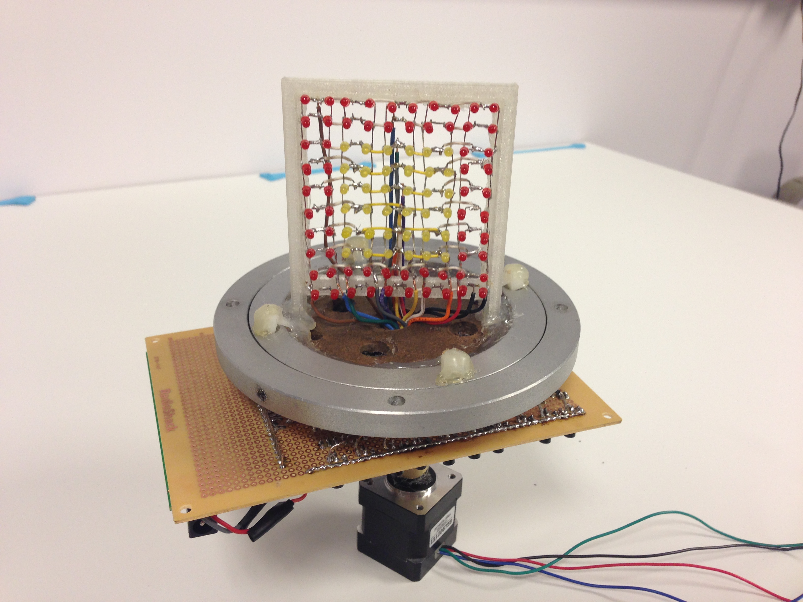
This project is very hardware heavy. First the LED display screen must be made. The 10 x 10 LED screen is constructed so that the rows have a common ground and the columns have a common Vdd, as shown in the appendix. This is so that each LED can be individually switched on when its two terminals are connected to Vdd and ground. The switch that controls which lines gets selected is done by a NFET which gets switched on when its gate gets pulled high.
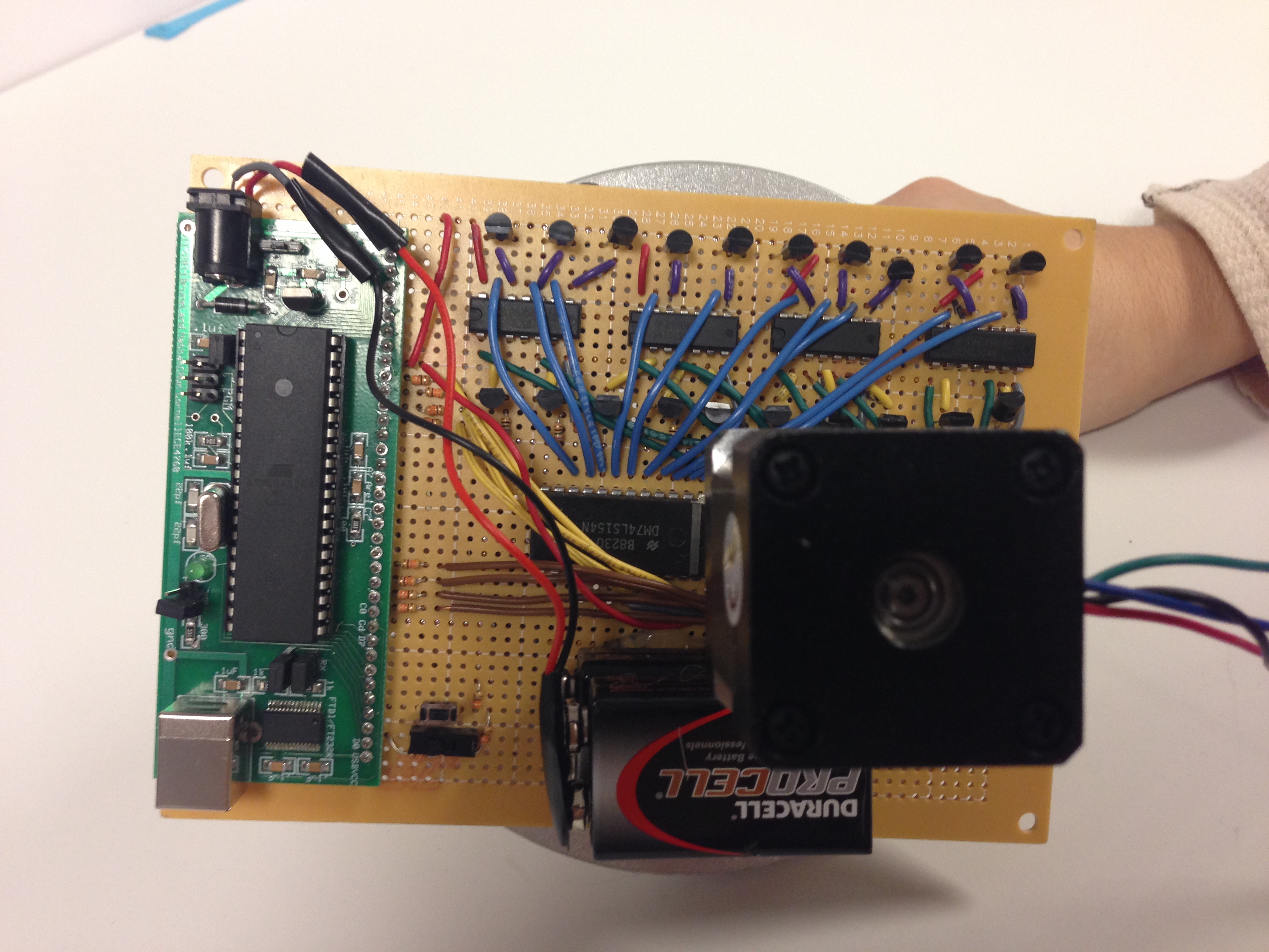
Once the LED screen is done, we need a custom LED driver circuit. This is done with decoders as shown in the appendix. Since there are 10 Vdd and ground to choose from, two 4-16 decoders are needed. The decoder takes in a 4 bit command to know which line to drive high. Unfortunately, the decoders we used are active low, therefore we needed to use place inverters after all 10 lines from the decoder as to drive the NFET switch. For example if we wanted to drive the LED on row 4 and column 5, PORTC would be set to 3 as to drive the 4th line to ground and PORTA set to 4 as the drive 5th line to ground. Then the inverters will invert the grounds to Vdd and close the NFET switches for the 4th row and 5th column to turn on that particular LED. This circuit needs to be implemented on a PC board.
Since the LED screen needs to be spinning to create the 3D visual effects, the whole LED driver circuit, LED screen, and the microcontroller will have to be mounted together so that they will all spin as not to tangle the wires. This was initially designed to be done with a ball bearing. However the motor was not powerful enough; thus the ball bearing was not used. The motor is connected to a rod which is then mounted perpendicularly to the PC board that have the LED driver circuitry. The PC board will then be mounted to a piece of wood that have the LED screen on top of it. Make sure that the PC board’s back is facing the piece of wood to make soldering to the LED screen easier.

Motor Circuit
Once the LED structure is completed, the motor circuitry needs to be designed as shown above. The motor needs four square waves that are 90 degrees phase shifted from each other. This can be done with two squares waves 90 degrees shifted and their inverses. These four signals will be generated on another microcontroller. The signals from the microcontroller will go to an H bridge as to give the signals the power needed to drive the motor. The motor needs 2.7 V and a 1A power supply but the microcontroller cannot supply so much current. Therefore the microcontroller and H bridge need two power supplies that have a common ground. The enable on the H bridge is always high as so that the output always the save as the input voltage-wise. The four outputs of the H bridge that are 90 degree shifted are wired to the motor as shown in the appendix.
There are buttons and switches attached to both microcontroller. The mircocontroller that controls the motor have a switch that tell the it to generate the square waves when set to high. The microcontroller that controls the LED screen has a button and switch. The switch functions as a pause when set to high and the button functions like a fast forwards to sync the visual display and song.
Software top
Matlab audio analyser
Since the goal of this project is to visualize music, we want changing visual effects throughout the song. More importantly, at strong beats or high notes of the song, we want to display a special visual effect.
In order to achieve this, we decided to separate the input tune into pieces of three seconds. For all the three second periods, the mean and variance of the signal is calculated. These two values are used to create a hash function that would choose 1 of then 9 visual effects to display by the equation: ((mean + standard deviation)*20) % 9 in the C program on the microcontroller. This equation was chosen because the result it gives will pick the visual effect with a certain amount of randomness.
We also want to locate every local maximum in the signal at an appropriate granularity so we can display some special visual effects at the local maximums. To achieve this, we first find the magnitude of the absolute maximum in the signal and saved it as Amax. Then, we find the local maximum every 250 ms since any finer granularity will make the local maximum too clustered for visual effects. For each local maximum, if it is greater than one fourths of the Amax, we save the time of local maximum in units of 100 ms. We decided to use the threshold of one fourths Amax because this gave a reasonable amount of local maximums that were spread apart well.
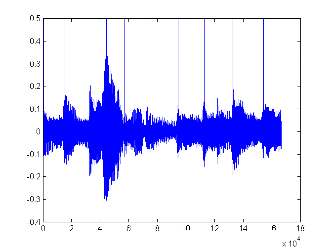
Plot of a single channel of audio with the detected local maximums annotated with a magnitude of 0.5
Integrating the MCU with MATLAB
In order to communicate the results from MATLAB to the microcontroller program, Matlab generates a header file for the C program. The header folder contains several pieces of information: the duration of the song, a 2D array for the mean and variance of every 3 second piece of the song and a 2D array that contains the time of the local maximums in units of 100 ms and the amplitude of the local maximum. The length of the song is written to the variable duration. The length of the 2 2D arrays are stored in length_mstd, length_pulse respectively.
MCU software
Motor control on MCU
The motor requires four square waves that are 90 degrees out of phase with each other as input. In order to generate the four signals on the microcontroller, we use PORTA0-PORTA3. The frequency of the square wave that is generated is around 1000Hz. This is done by setting the timer to have a prescalar of 128. OCR0A is set to 31 and the ISR interrupts on timer compare match. This means that the ISR will be executed every 31*128/16000000 = 0.000248s. In the ISR, a variable 'count' is cycled from 0 to 3 to 0 again. The motor control has a main while loop. The while loop will execute the following commands when a switch is on. When the switch is off, nothing is done.
As shown in the table, if count is 0, PORTA is set to 9. If count is 1, PORTA is set to 10. If count is 2, PORTA is set to 6. If count is 3, PORTA is set to 5.
This generates a square wave because as shown in the following table, there are 2 bits that are high at each moment. The bits that are high alternate to produce 4 square waves that are exactly out of phase with each other. Thus the square wave has a frequency of 1/(4*0.000248) = 1008 Hz. This corresponds to a speed of 1008/200 = 5.04 rps as the motor has an angle step of 1.8 degrees. While the microcontroller can generate faster square waves, 5 rps is the fastest the motor can go.
| Count = 0 | Count = 1 | Count = 2 | Count = 3 | |
|---|---|---|---|---|
| PORTA0 | 1 | 1 | 0 | 0 |
| PORTA1 | 0 | 0 | 1 | 1 |
| PORTA2 | 0 | 1 | 1 | 0 |
| PORTA3 | 1 | 0 | 0 | 1 |
Port control on MCU
In order to make programming easier, PORTA0 to PORTA3 are the inputs to the decoder for the rows. PORTC0 to PORTC3 are the inputs to the decoder for the columns. PORTD0 is for a switch that when turned off, freezes the timing bookkeeping on the MCU. When the switch is off, the display of visual effects is halted. When the switch is turned on, the visual effect will continue where it left off. This implementation is chosen because when the user wants to stop the music and display, he or she can just turn off the switch. When the music is played again and the switch is turned back on, the music and display will still be in sync. PortD2 is connected to a button. When the button is pressed, the internal time of the micro controller will be increased by 100 ms. This design choice was made because it is possible that the user would notice that the display lags slightly behind the music. When this happens, the user can press the switch as many times he or she desires till the display is in sync with the music again.
Visual effect timing control on MCU
In the program, time is kept in units of 0.5 ms since the nature of our system does not require finer granularity. Through experimenting, 0.5 ms is sufficient for the timing controls for the visual effects. In order to set 50ms as the time base, timer 0 is set up with a prescalar of 64. The OCR0A register is given a value of 124. Thus, timer 0 would interrupt every 0.5 ms.
For the timing control, the main function executes as long as the internal time (will be referred to as maintime) is smaller than the duration that is written in the header file by matlab. In the main function, when the switch is off, nothing happens and the maintime is also stopped. The following discussion applies to when the switch is on. The button for fast forward is debounced every 105 ms to see if it is pressed. Also, there is a variable: mstd_index that is initialied to 0 and incremented to go through the 2D array of mean and standard deviations. The program checks to see if the time is at a multiple of 3 seconds. If it is, (the mstd_index + 1) * 60 is checked against maintime. If it is, mstd_index is incremented since this means that while displaying visual effects, the program is behind on schedule because it was playing other visual effects when the most recent 3 second mark passed. The 3 second visual effect functions are written to take in an integer as an input. The reason for this implementation choice is explained in the section: implementations in software that did not work. On a high level: every 3 second visual effect is separated into 10 portions because there are 10 rows and columns. This input index to the function chooses which rows and/or columns will be displaying a part of the visual effect. In order for human eyes to see these individual portions, each individual portion will be displayed for 260ms. Thus, when a visual effect is first chosen, a variable that signals the beginning of the counting of 260 ms for timer 0:i_n will be set. Then, in the while loop, we will always check if the 260 ms is up. If it is, i_n will be incremented. i_n will be set to 0 once it reaches 40 to avoid overflow. If the 260ms is not up, i_n will be unchanged. Also, in the while loop, another variable: lm_index is initialized to 0 and is used to go through the 2D array that contains the local maximum times. In the while loop, we always check if the lm_index entry in the local maximum time array is later than maintime. If it is, we will check the lm_index+1 entry in the local maximum array to determine if we are too far behind on schedule recursively. We stop when we are at the entry that is the most recent local maximum. Then, a local maximum effect will be chosen according to the magnitude of the local maximum. The local maximum effects are different from the 3 second effects in that they are shorter and more intense.
Visual effect generation on MCU
The layout of the LED screen with column and row numbers are as followed to help the explanation

The column LEDs are connected to Vdd and the row LEDs are connected to ground. In order to turn on one LED, we need to choose the corresponding row and column. Therefore the MCU needs to cycle each LED in order to display an image. In other words, the MCU has already cycled 100 times in order to display an image that involves every LED. Thus if we want to turn on a whole row, we will choose the ground of 1 row and cycle through choosing the columns very quickly. We implemented the following visual effects:
The effects that are going to be displayed in the three second time periods:
The effects that are going to be displayed at the local maximums:
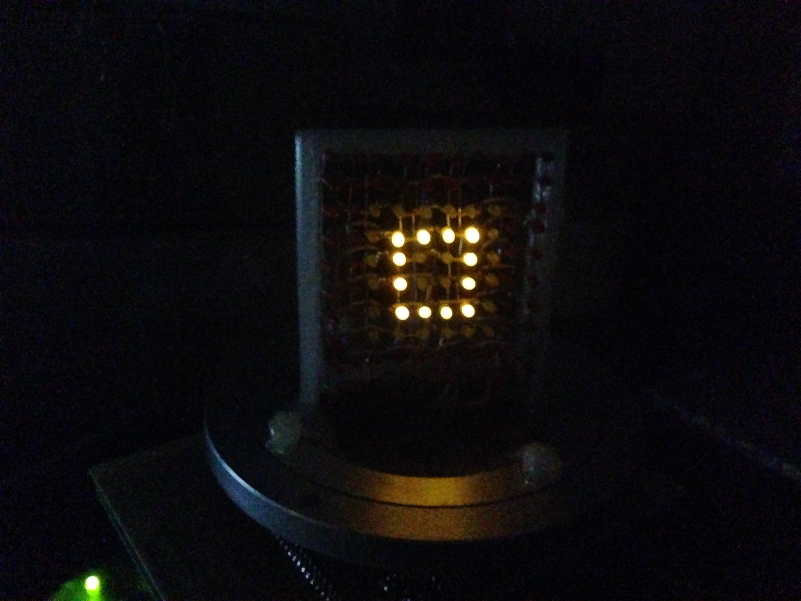
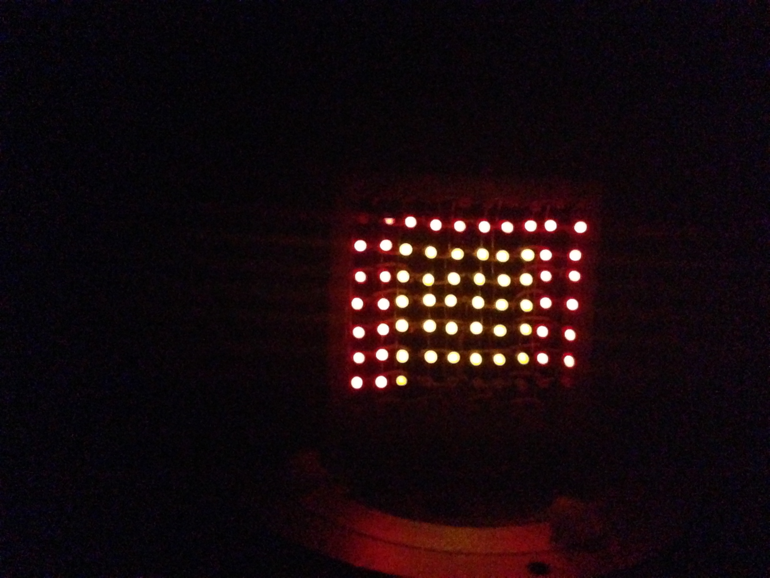
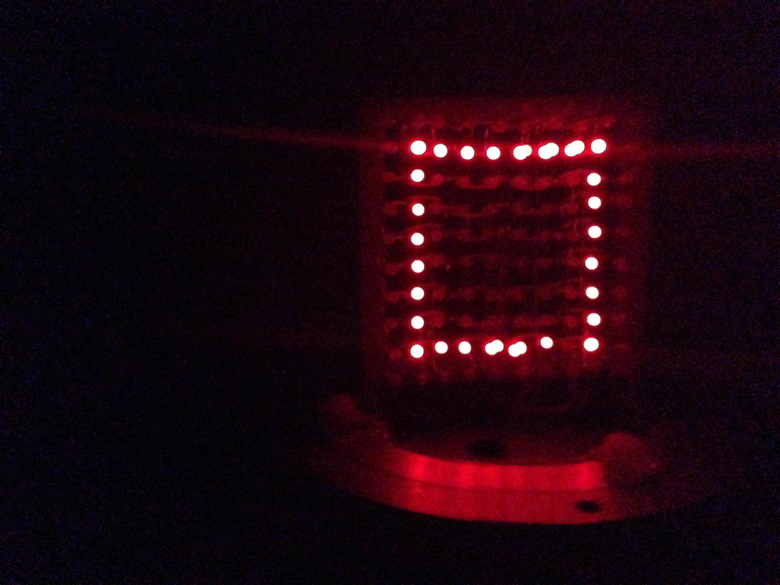
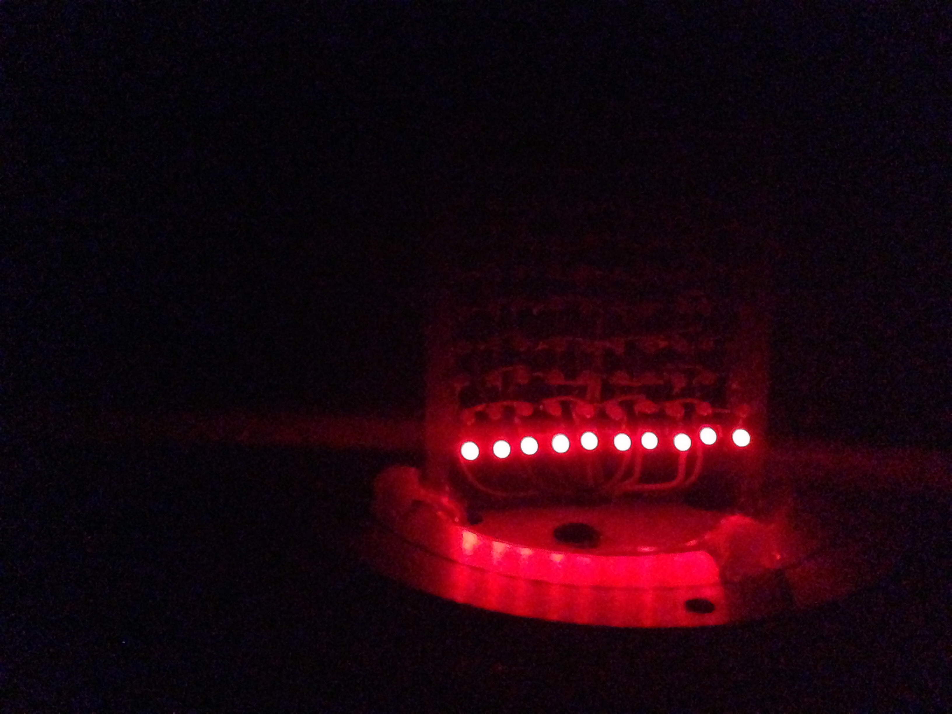
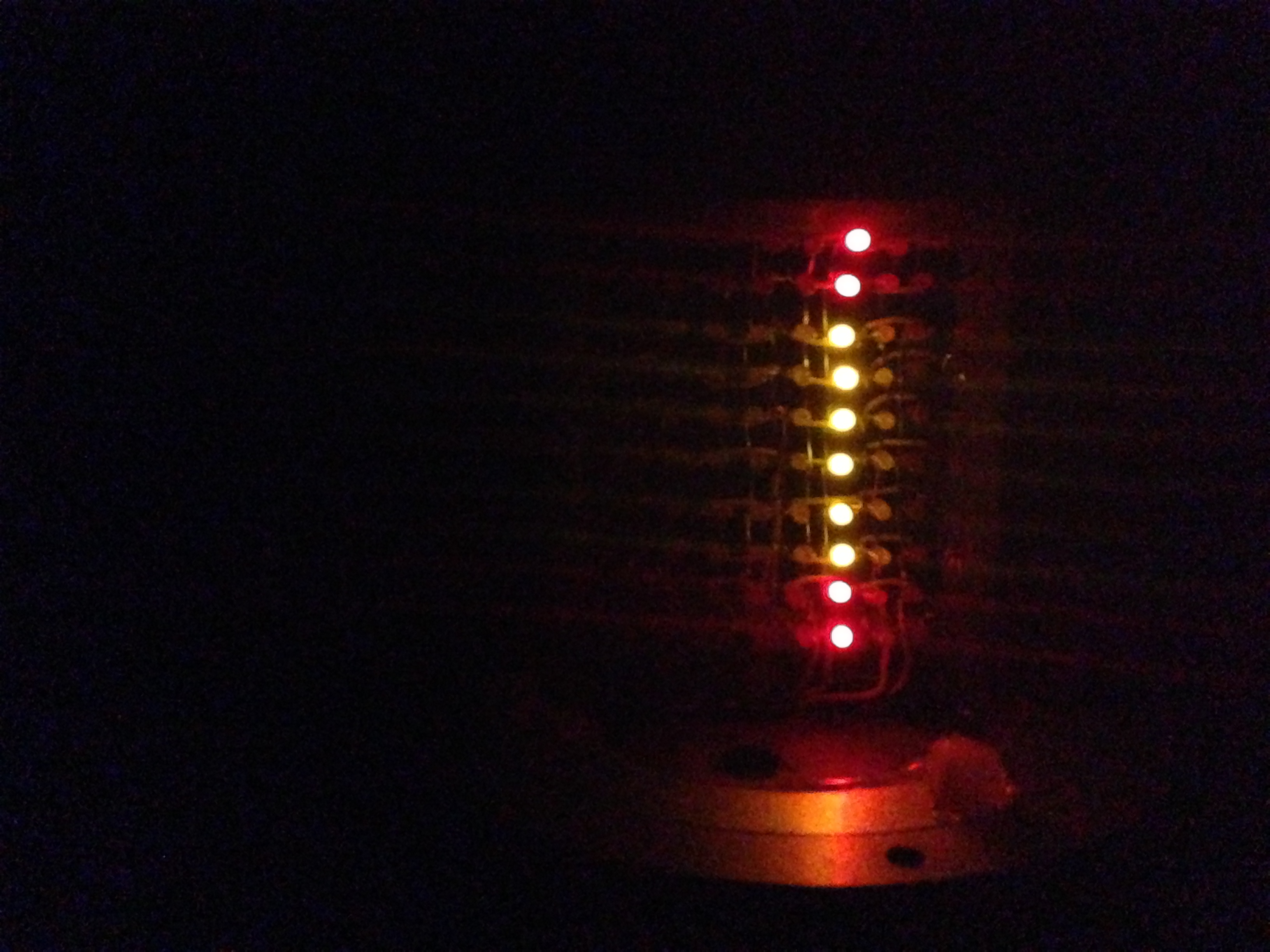
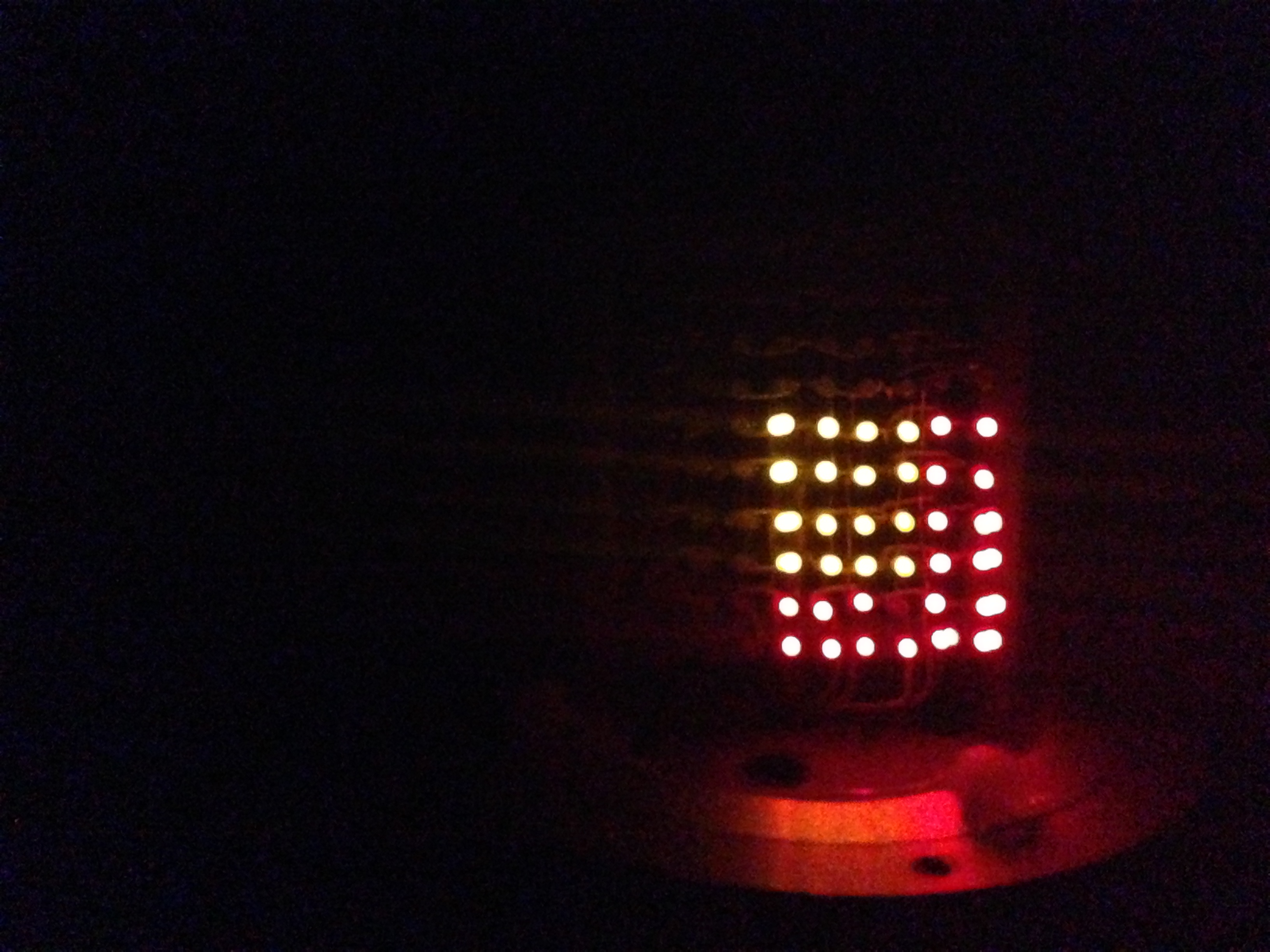
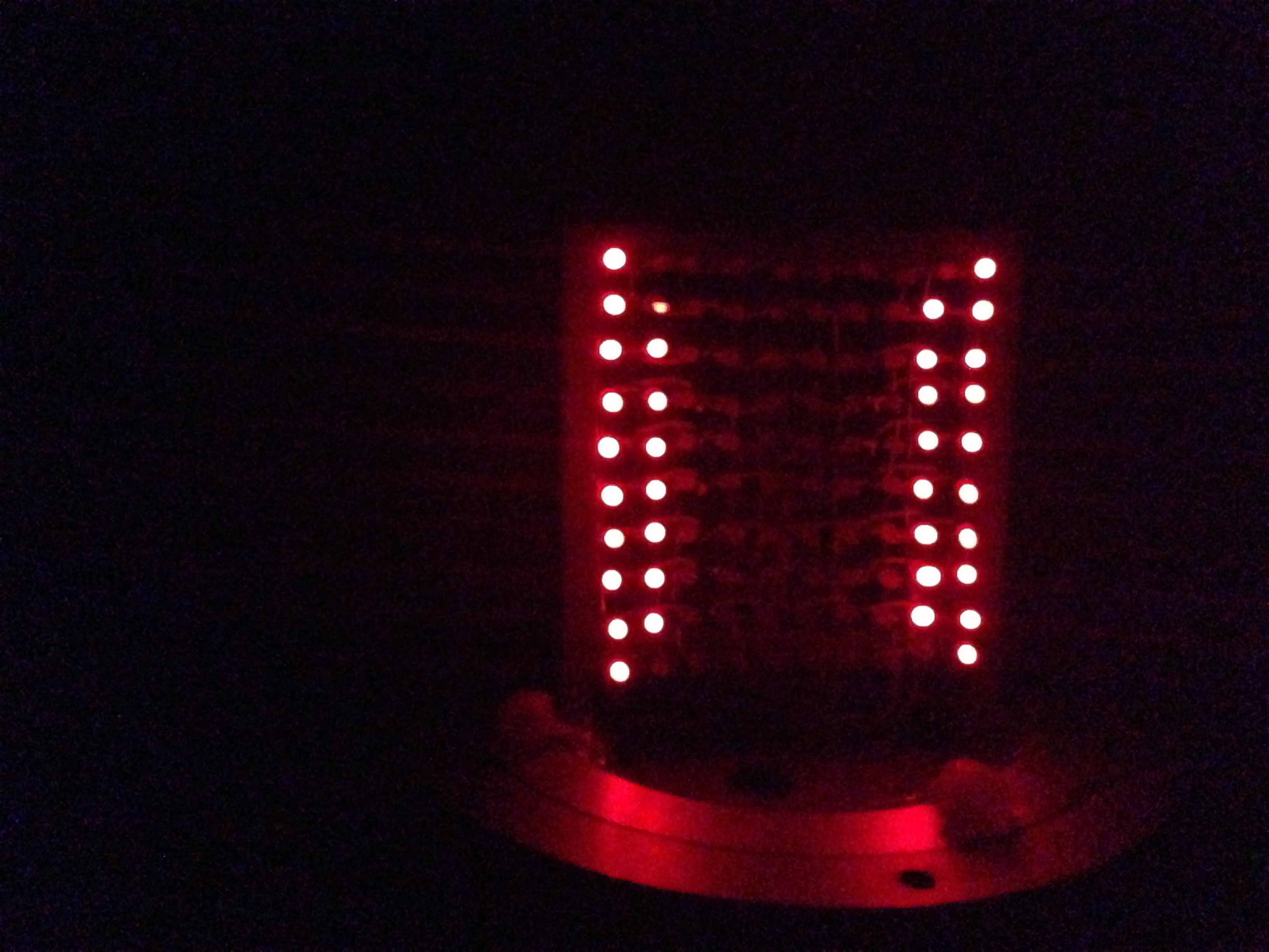
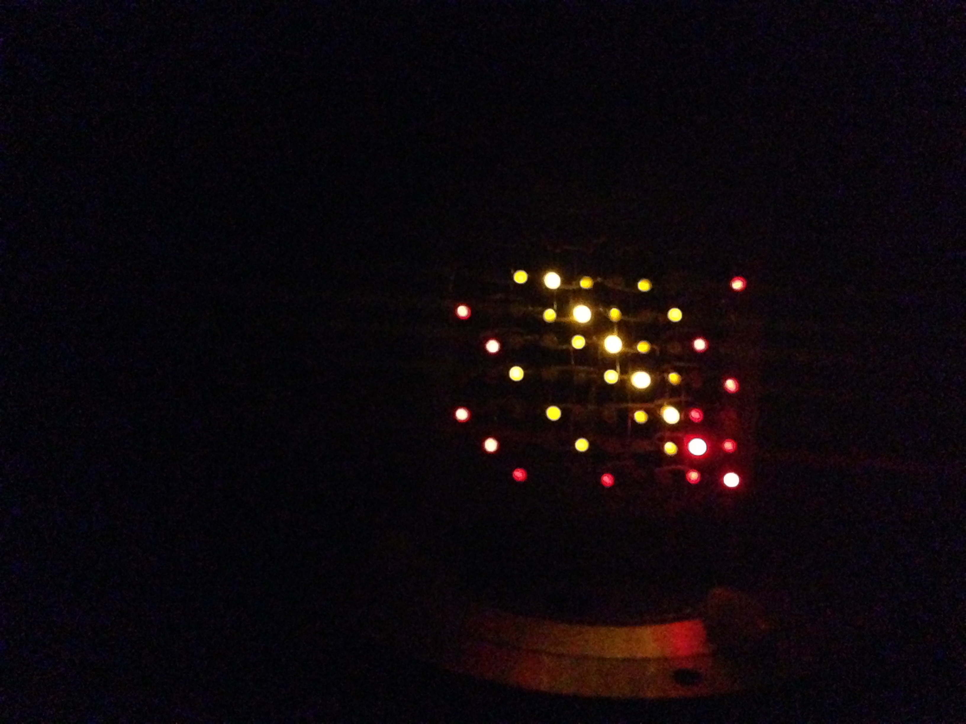
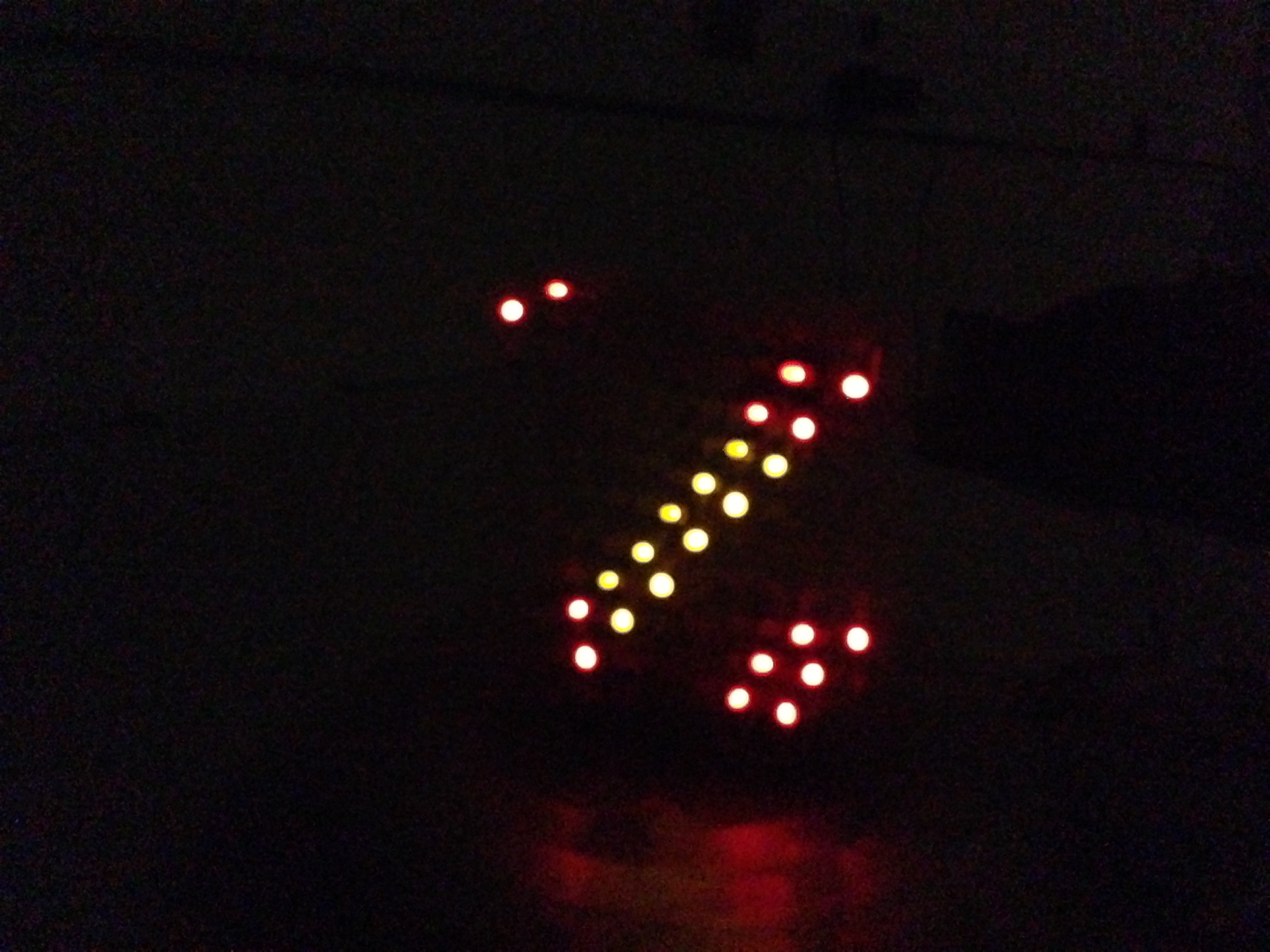
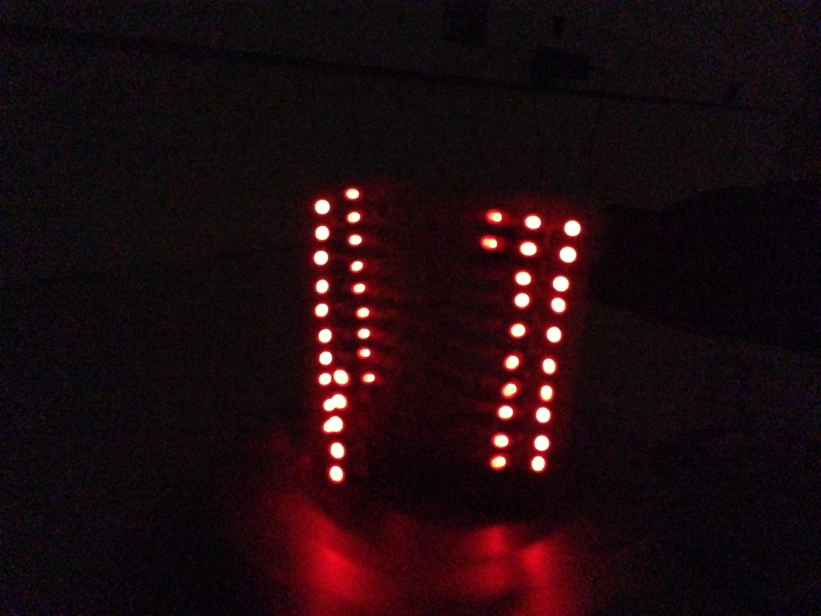
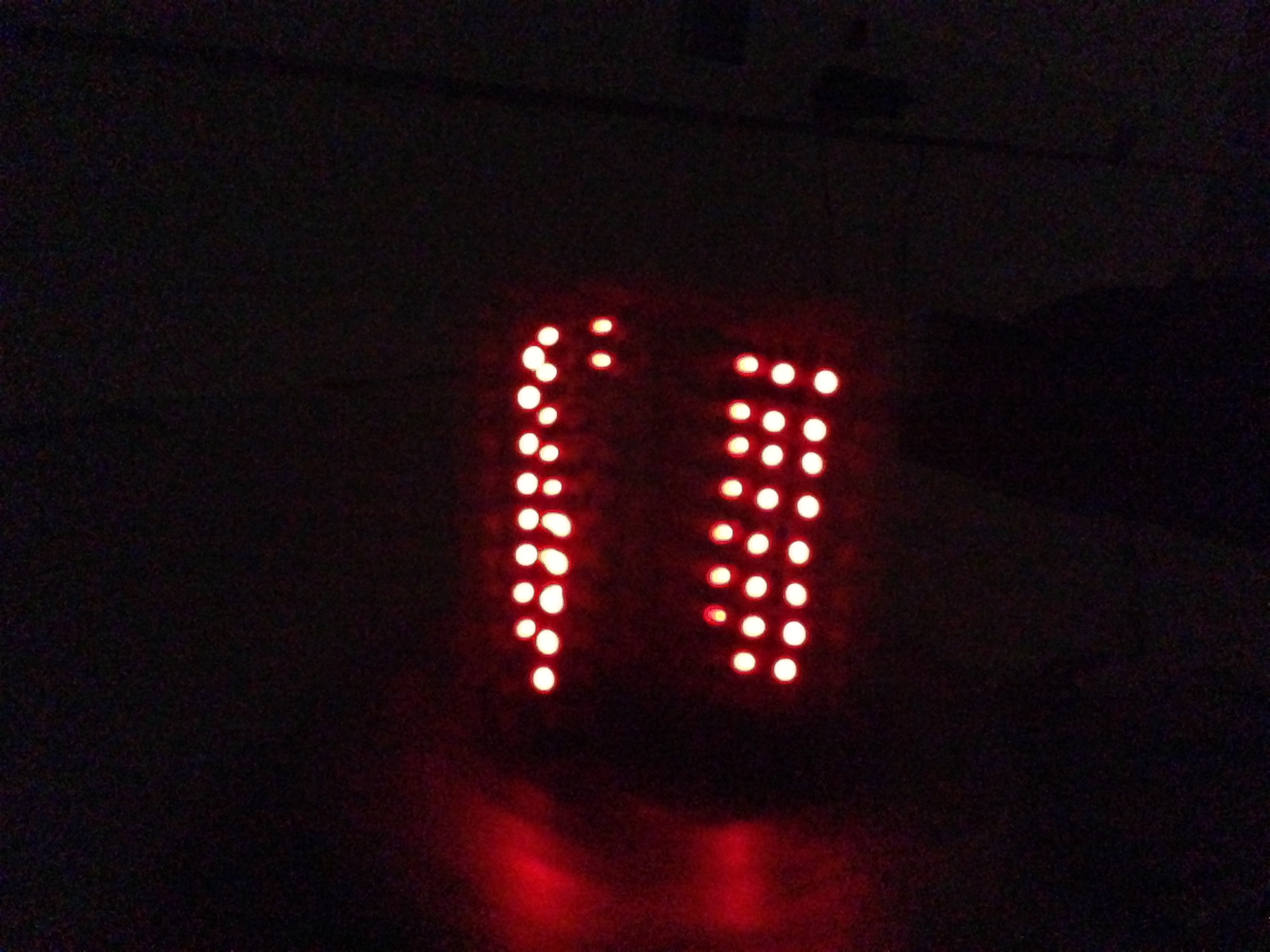
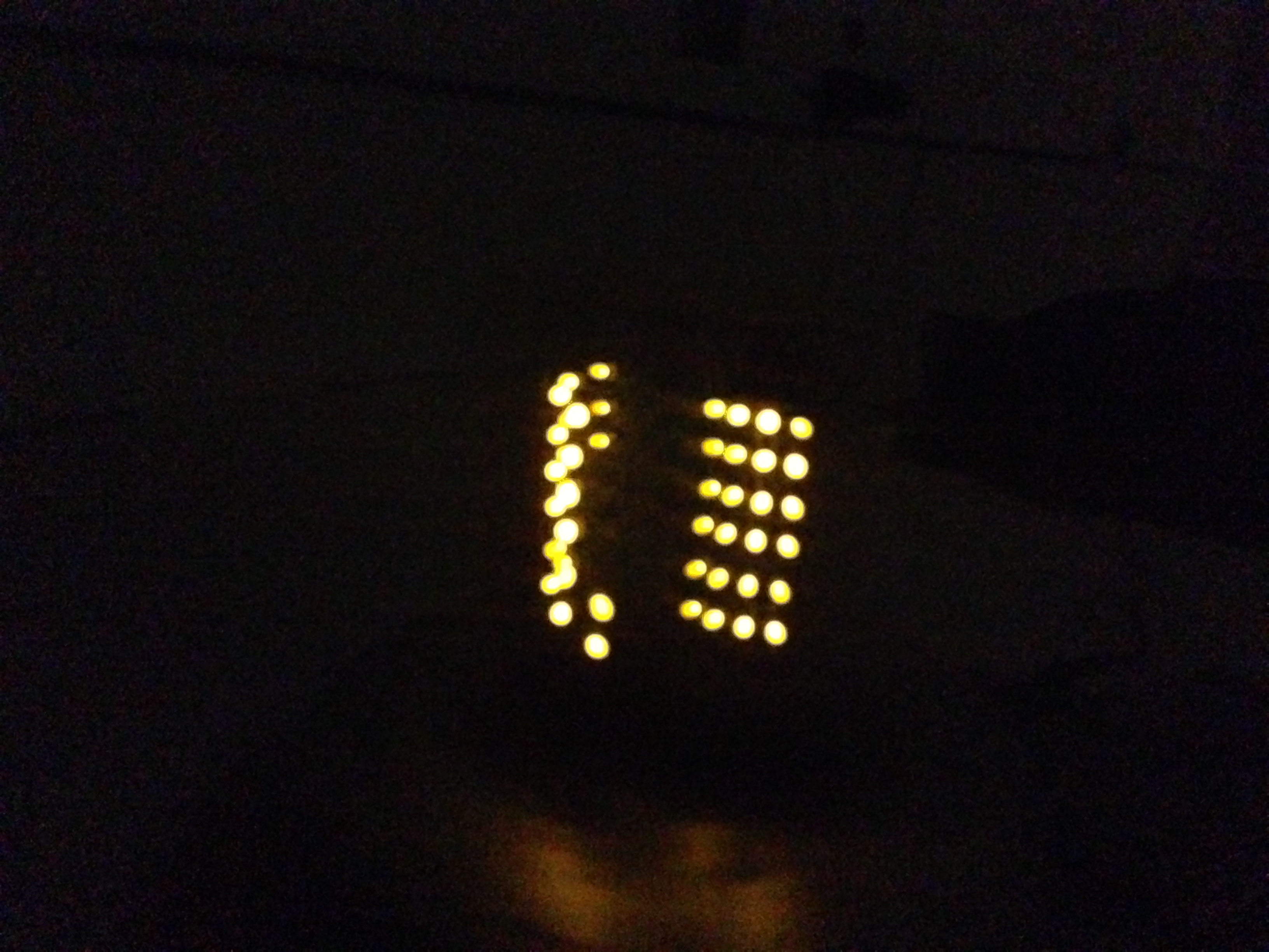
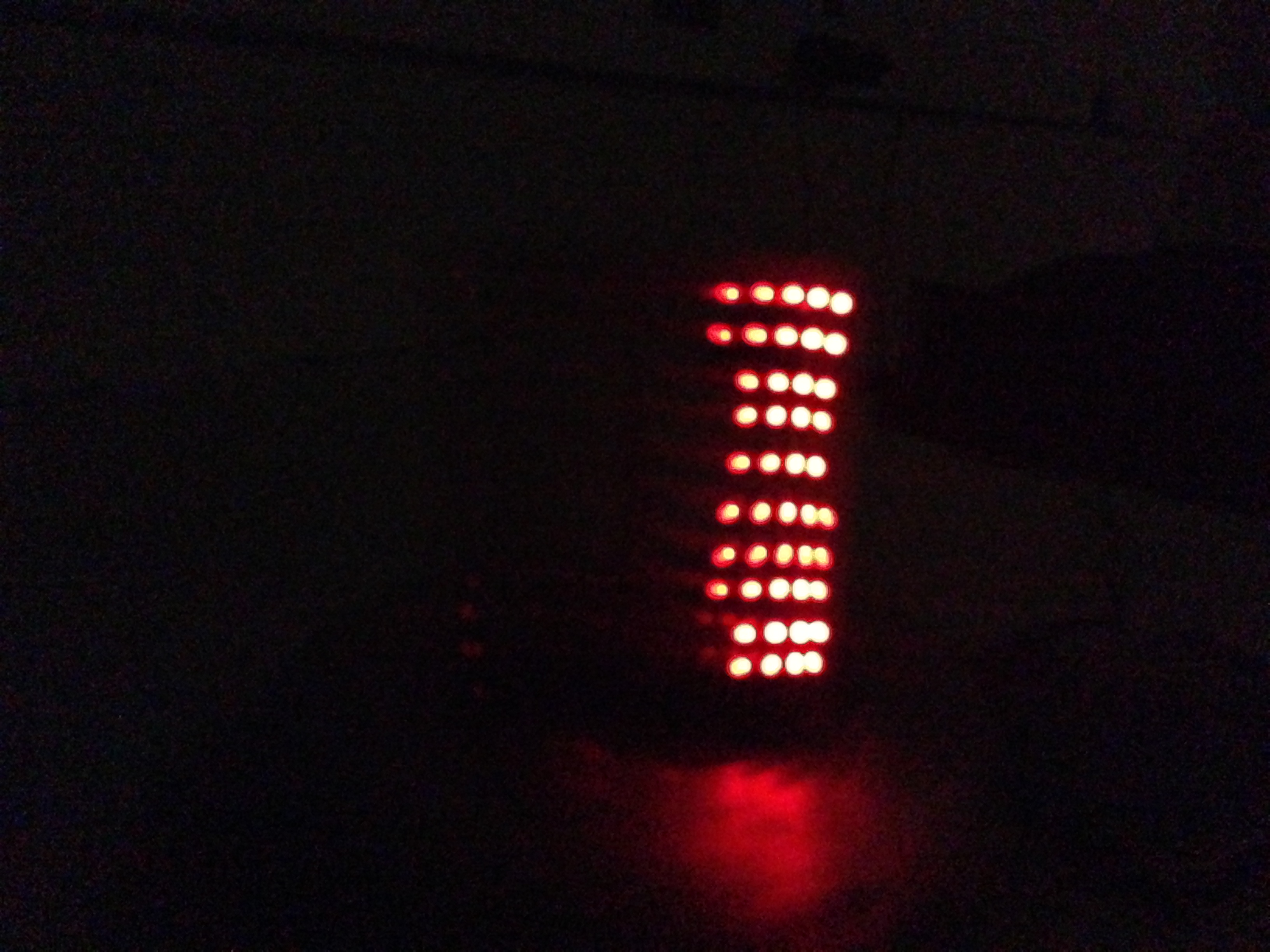
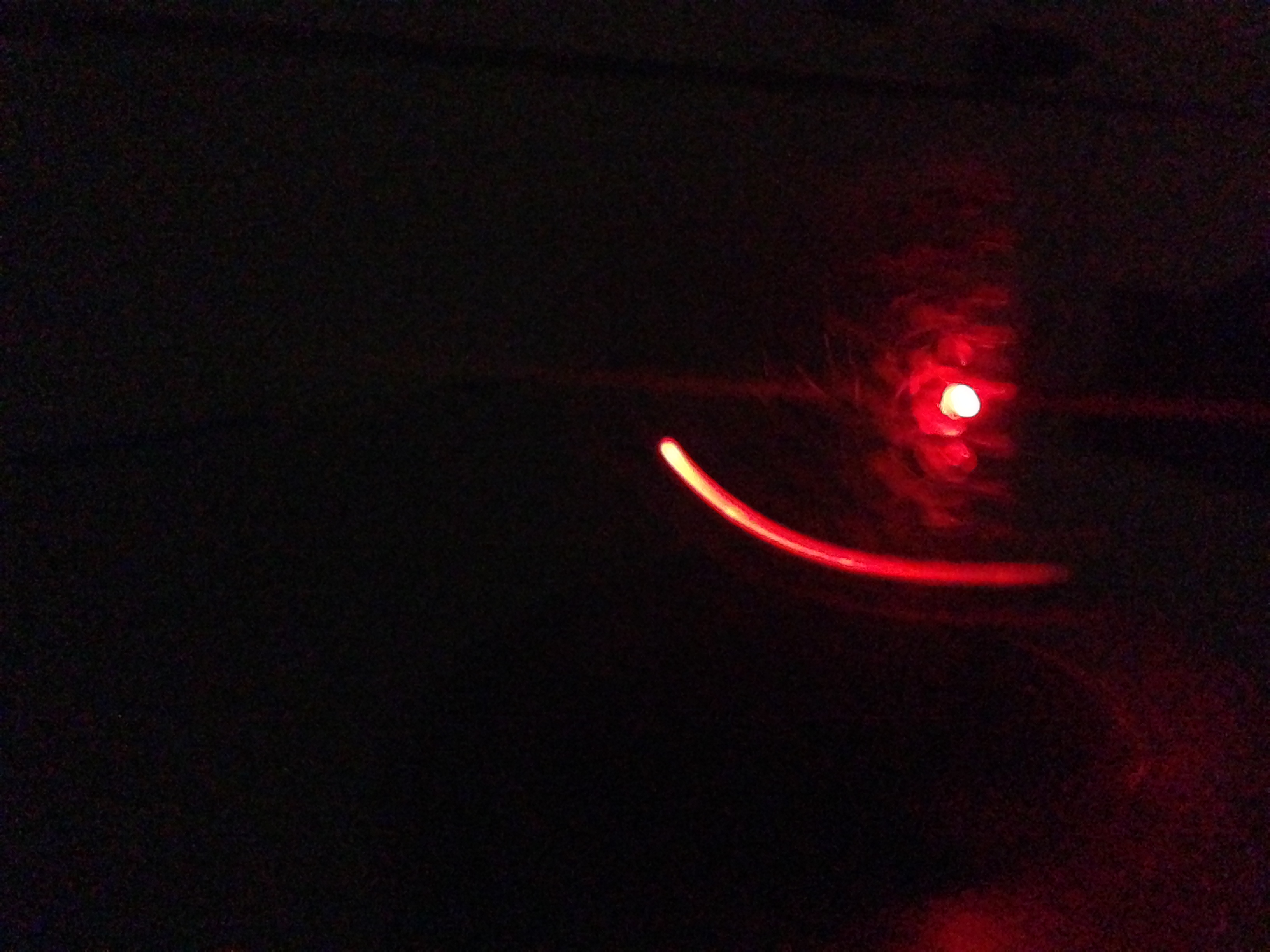
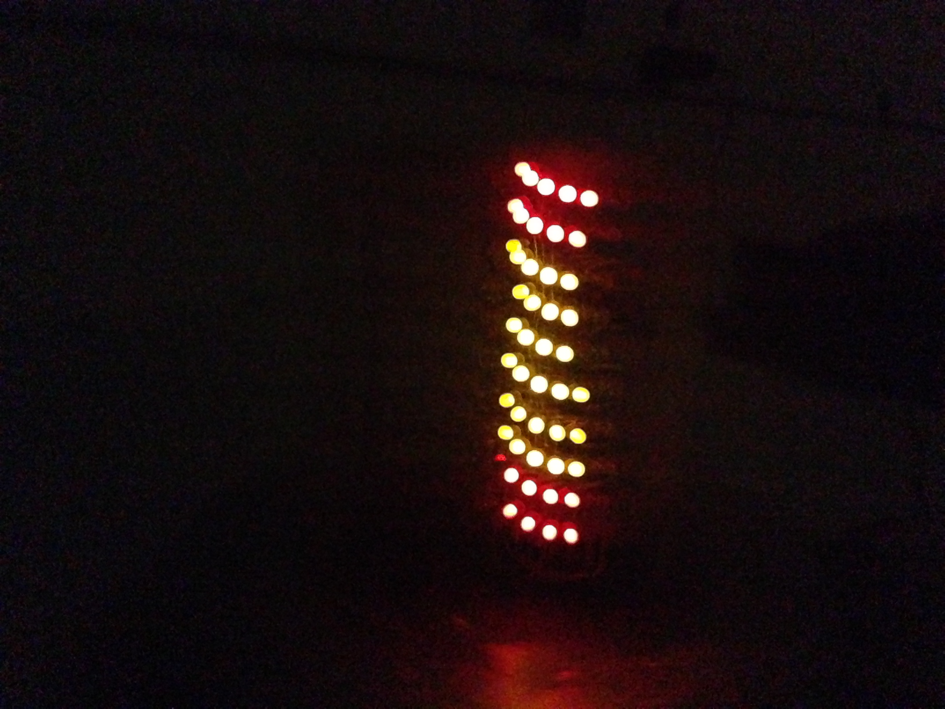
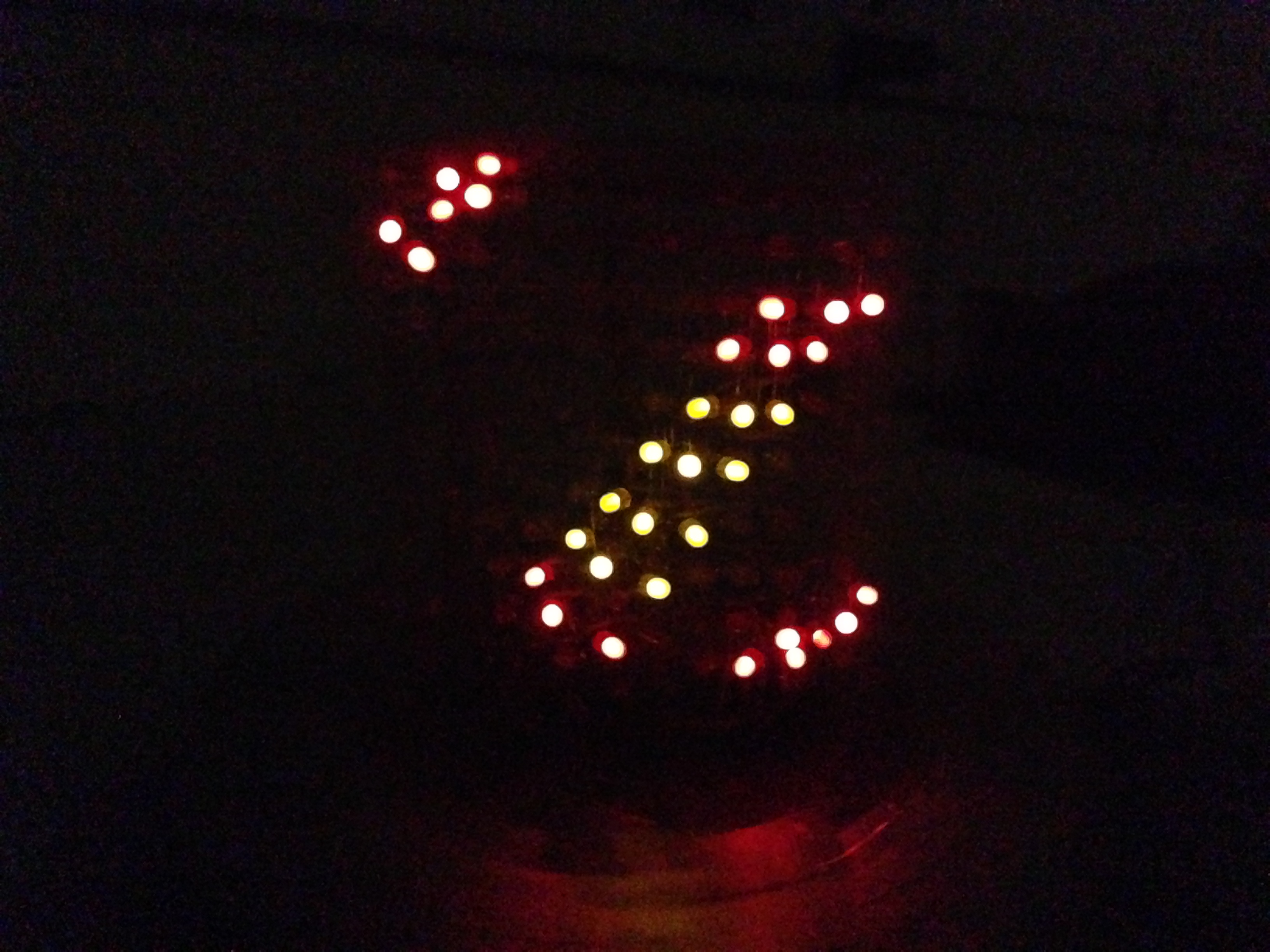
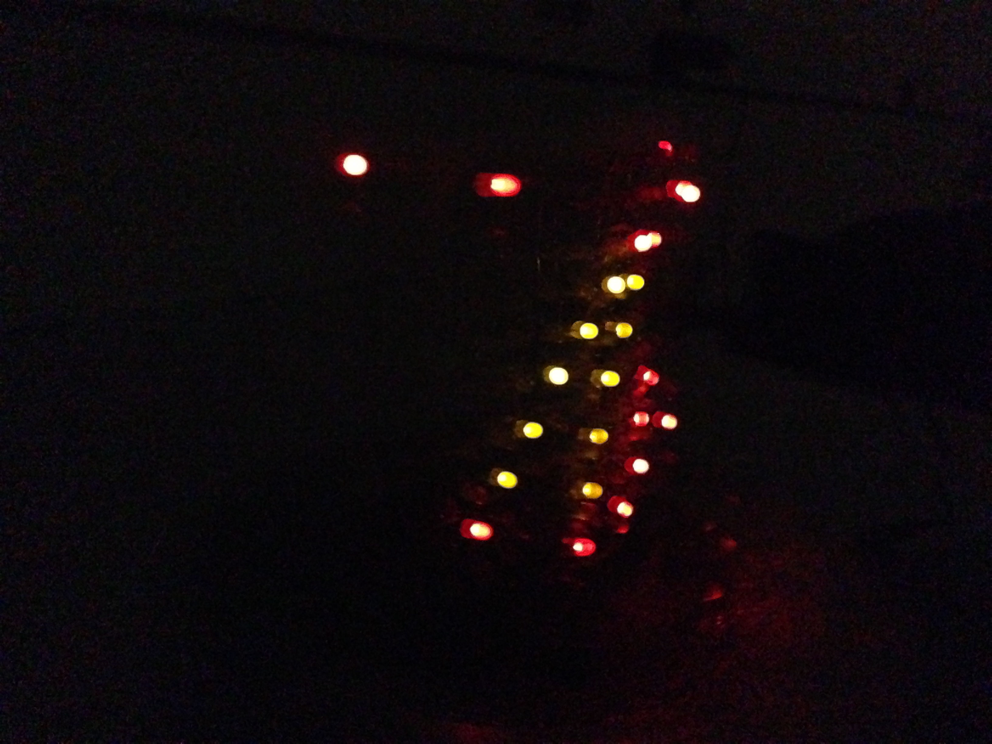
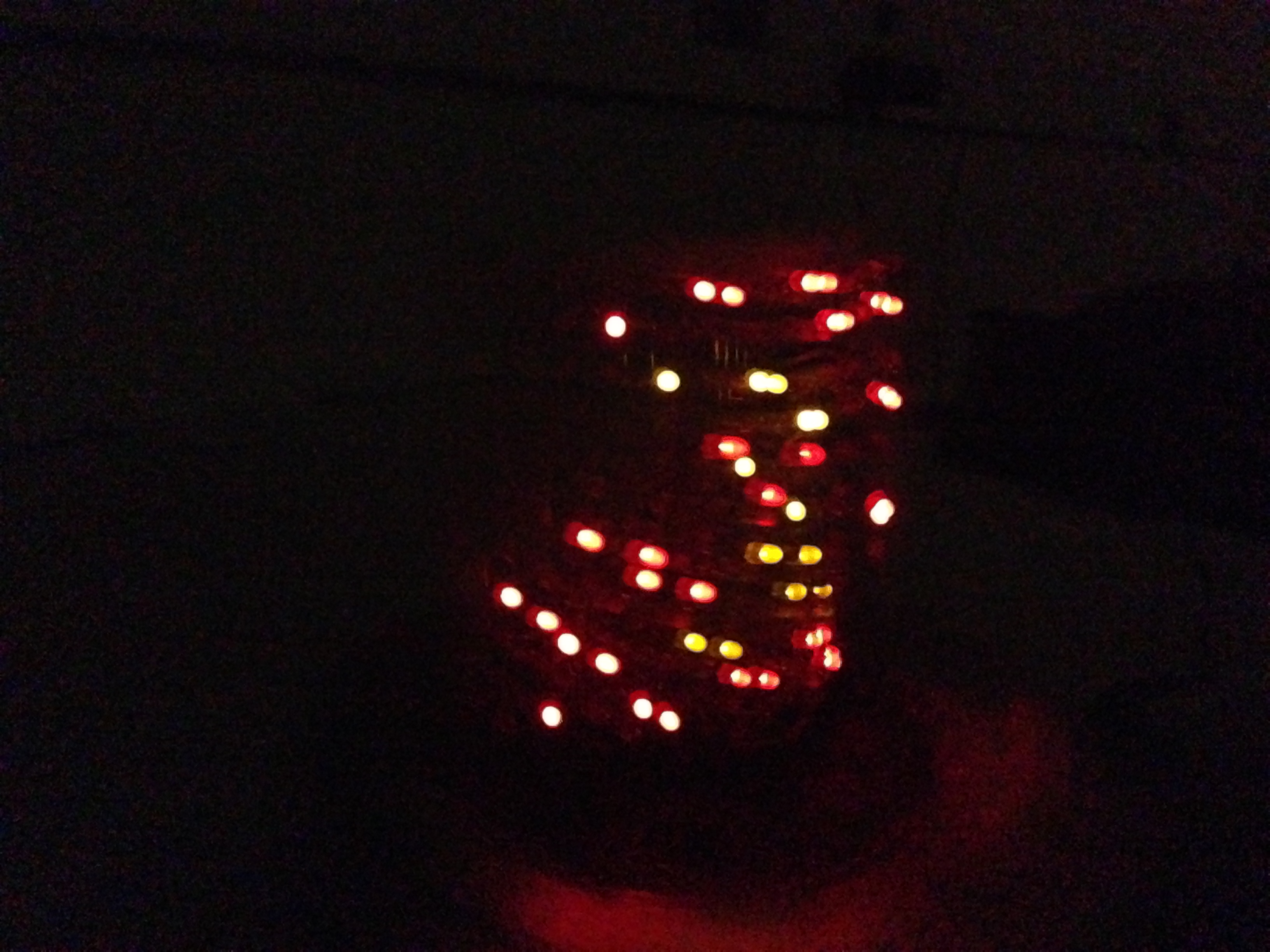
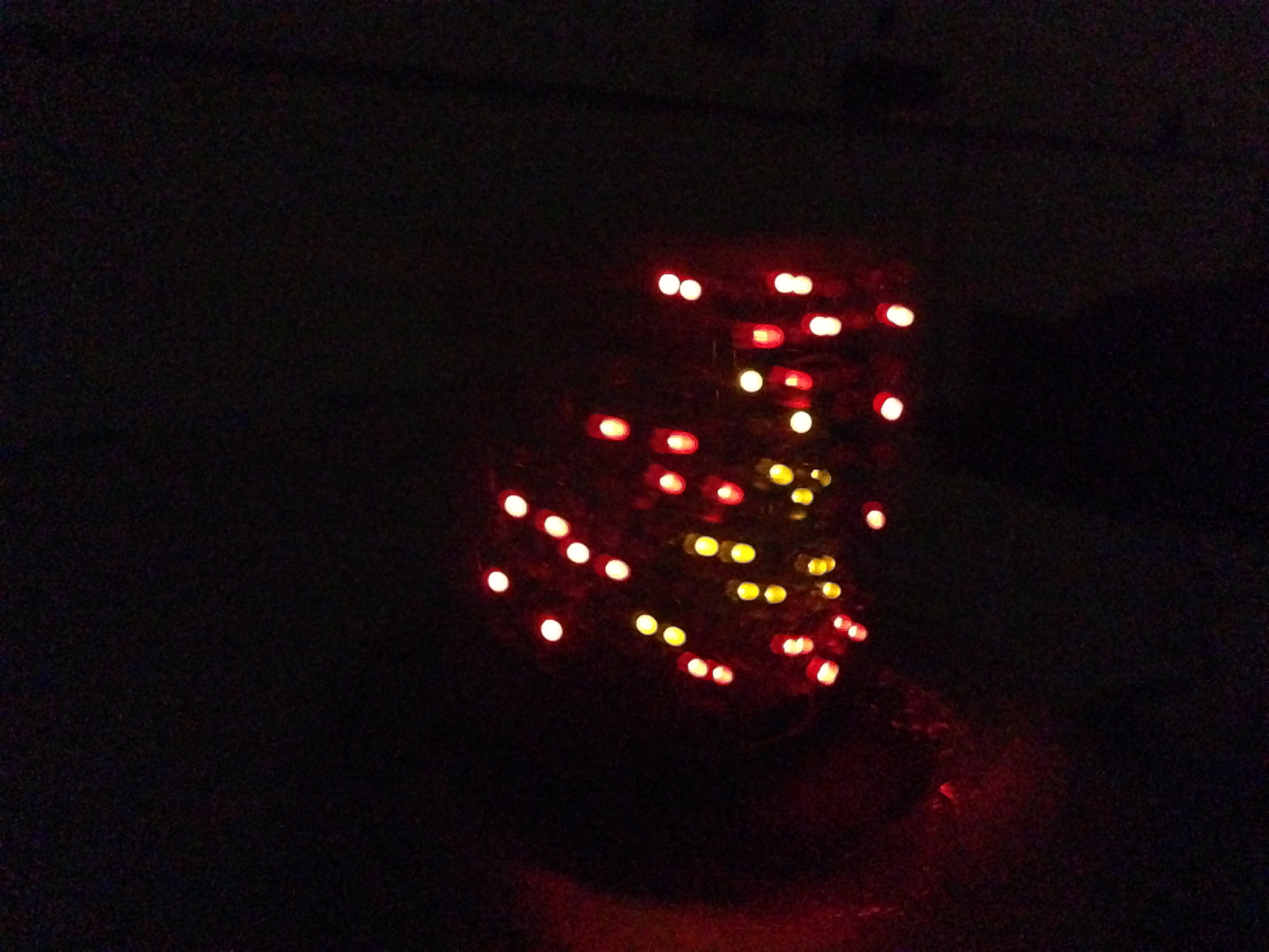
The above effects are the descriptions in 2D. When the screen spins, the effects gives the perception of collimated depth. Following are the visual effects in 2D and the 3D images. We tried to capture the different effects separately. However, at any one instance only 1 LED is on. This makes the effects very hard to capture on camera.
 | 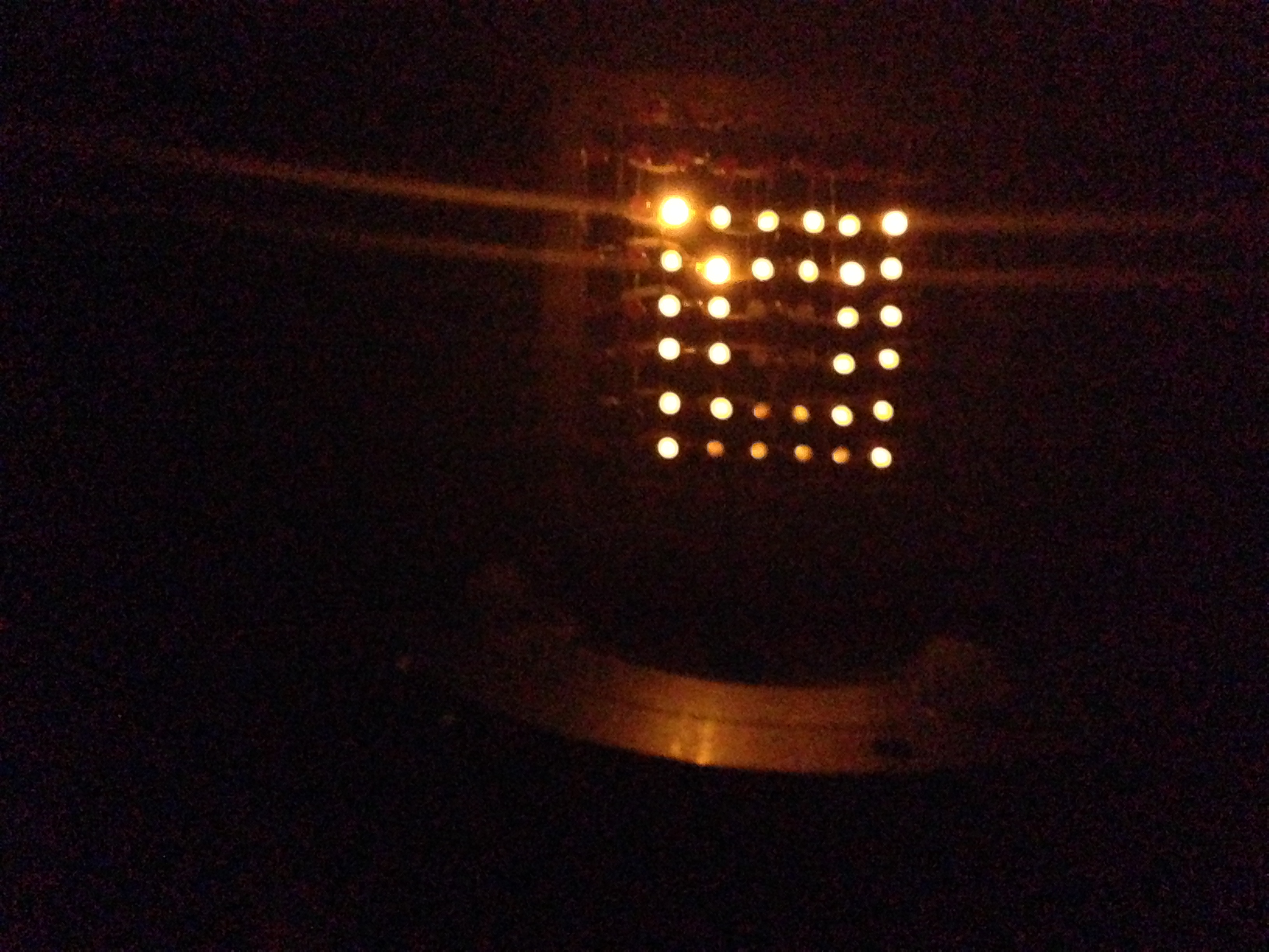 |  |
 |  |  |
 |  |  |
 |  |  |
effects in 2D
 |  |  |
 |  |  |
 |  |  |
 |  |  |
 |  |  |
 |  |  |
 |  |  |
 |  |  |
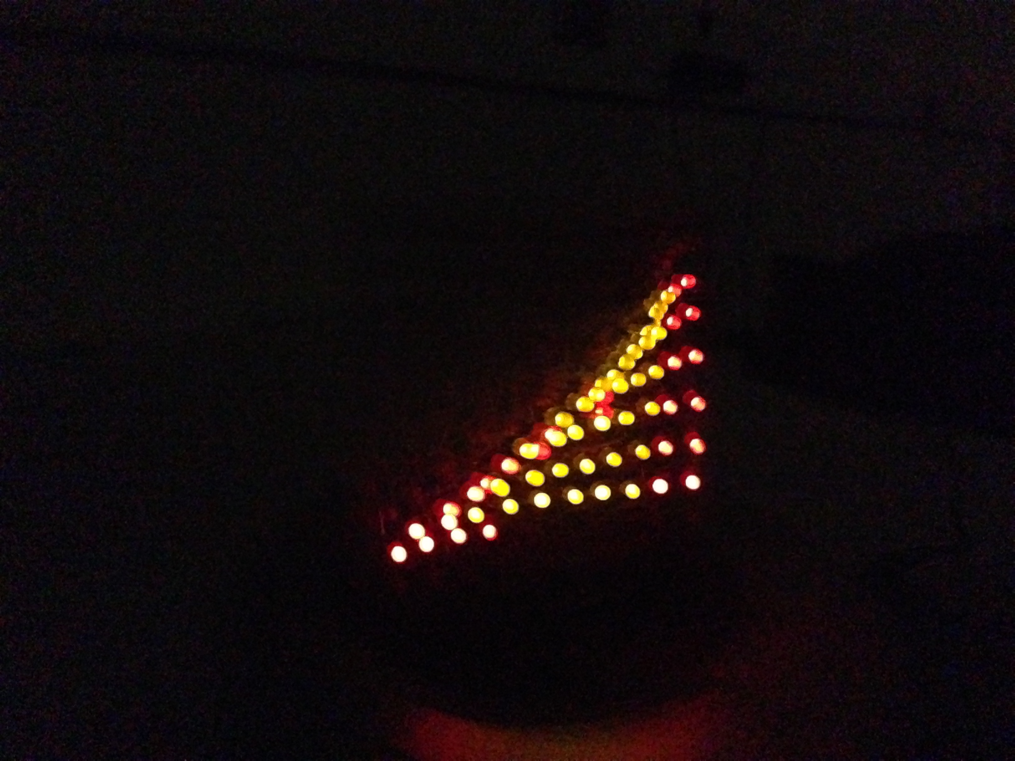 | 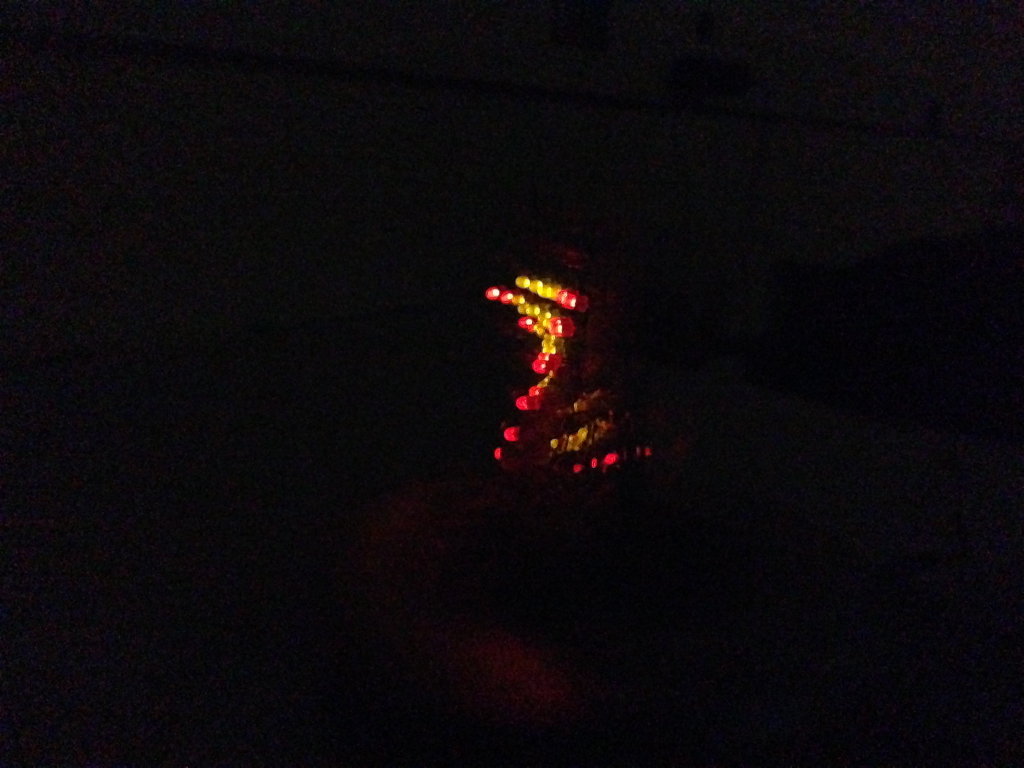 |  |
Effects in 3D
Implementations That Did Not Work
Hardware
At first, we wanted to mount the LED screen on a ball bearing so that the inner circle will spin while the outer side will remain stationary as to give support to the structure. The outer circle would have been mounted to a frame as make the whole structure stable. However the ball bearing needed more torque in order to turn than the motor can provide. Thus we could not use the ball bearing and our structure is not very stable.
Matlab audio analyser
Initially, we tried to analyse the input tune in frequency domain. We attempted to do FFT on the audio signal after applying smoothing to reduce noise in order to extract the beat. However after obtaining the frequency spectrum after a series of processing, there were no significant maximum points. We also looked into software that other people developed for their projects. We found the Matlab code online that implemented beat tracking with dynamic programming according to an algorithm developed by Dan Ellis. When this algorithm was applied to music in intervals of 3 seconds, it identified a beat for each interval but did not offer the accuracy that we wanted for detecting local peaks. Thus, we eventually did all matlab processing in time domain.
MCU control
At first, all the visual effect functions we wrote were independent of each other. Meaning that they took in no input arguments and executed to completion when they were called. However, we realized that this increased the complexity of the program significantly since this would mean that we would need interrupts at local maximum times to display the special "beat effect". Thus, in the final implementation the 3 second effects took in arguments. The main control would keep track of an index that the 3 second effects methods take in. The local maximum effects accept no input since they are relatively short and are played to completion.
Results top
Speed of Execution
In our project, speed of execution is an important issue when we want to make several LEDs seem to be on at the same time. This speed of execution is used to control the visual effects. In our project there are two important timing issues:
Through experimentation, we discovered that making every LED light up for 0.5 ms gives the best results. When all the LEDs on the screen are each on for 0.5ms one after the other, the whole screen seems to be lighted up.
Another timing issue is the speed at which the LED screen is spinning. Regular films use about 15 frames per second. Therfore, we ideally wanted 10 rps but due to motor limitations, we got 5rps.
Accuracy
While accuracy is important, we do not have a strict requirement for it. We only need the LEDs to seem to be on simultaneously and the motor to spin fast enough to create a perception of depth. The LEDs that we want to shine turns on as expected. The motor speed is at an acceptable level.
Safety
In our project, we do not have voltages or currents that are dangerous to people. Also, the brightness of the LEDs are not harmful to human eyes. The only safety concern would be the stability of the overall structure. To mitigate this hazard, there is always a weight or a hand to hold it.
Interference
Our project would not interfere with other people's design, except maybe annoy them with the LED lights flashing. Nor would other people's design interfere with us since our project are all hard wired and soldered.
Usability
Our project is simple and easy to use. As described in above sections, the user would need to run matlab once. Then, the motor and LED display are enabled by two switches. One thing we could have done to improve the ease of access for our project is to create a Matlab GUI with a simple push button to do the audio analysis instead of having to modify code.
Conclusions top
Did Our Design Meet Expectations?
We feel that overall, our design met our expectations. We are able to take in an input song, analyze it, and generate visual effects according to the tune. The final design does not require much user interaction since it only needs the user to run matlab, turn on the motor control and turn on the led display control. The user is able to make the visual effects skip forward by a short amount of time by pressing a button
There are aspects of our final design that could be improved. First, the motor control could be synchronized with the LED display control by using blue tooth. The microcontroller that controls the LED could be the master. When the user switches on the button for the LED screen, the LED microcontroller could tell the motor microcontroller to start generating the square waves that are needed. Another aspect is that the button that implements the fast forward function is now on the spinning stand. This is because we decided to add the fast forward button at the end of the design phase. Currently, if the user wants to press the button, he or she would need to slow down the spinning platform and press the button. Ideally, this button should be more easily accessible. The final aspect is that we could have used a DC motor as the sy36st35 motor is not powerful nor fast enough for the propose of this project. The sy36st35 motor can only go up to 5 rps and 28N of radial force and a 1.8 degree turn per step. We need a motor that can turn the ball bearing at about 10 rps.
Overall, we feel that the whole design is simple, portable, cost friendly and cool. We feel that we have made full use of the resources available to produce a good final project.
Did Our Design Conform to Standards?
For debugging purposes, we used the UART. We use a baud rate of 9600. We used the UART code provided in the ECE 4760 labs.
Intellectual Property Considerations
All the code and hardware setup have been originally developed by us. To the best of our knowledge, we do not violate any copyright rules
Ethical Considerations
Throughout the design of the final project, we carefully abided by the IEEE code of ethics. We carefully designed our project so that it would not be harmful to humans. When we spin the LED stand, we didn't spin it to be at a speed too high so that it might hurt people. It is safe to touch the LED screen when it is spinning since the speed is around 5 rps. When designing our project, we also strived to make our final portable and easily accessible. Also, when designing the technical portions of our project, we researched online to avoid conflicts of interest. We searched for related patents and watched numerous videos to see if someone else had made such a project. We also acknowledge the design flaws in our system. With respect to ethics concerns relating to ECE 4760, we made sure to choose a final project that properly challenged us in the 5 weeks and would make full use of the functionality of the microcontroller. Thus, we chose a project that uses the micro controller for its real time control and fast execution of code. We feel that throughout the design of the final project, we have followed the IEEE code of ethics.
Legal Considerations
Appendices top
A. Schematic

Schematic of Single LED Row

Schematic of Decoder for Rows
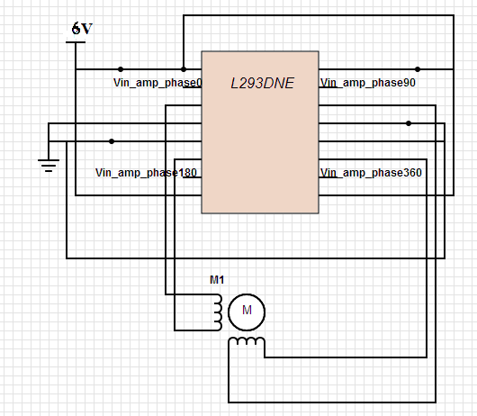
H Bridge Schematic
B. Parts List and Costs
| Part | Cost/Unit | Quantity | Total Cost |
|---|---|---|---|
| Atmega 1284 | $8.00 | 1 | $8.00 |
| Atmega 1284 board | $5.00 | 1 | $5.00 |
| 74LS04 Hex Inverters | $0.25 | 4 | $1.00 |
| White Board | $6.00 | 1 | $6.00 |
| H bridge | $2.35 | 1 | $2.35 |
| 74LS154 4 to 16 Decoder | $0.9 | 2 | $1.80 |
| PC breakout board | $4.49 | 1 | $4.49 | 2N7000BU NFET | $0.41 | 20 | $8.20 | WP710A10ID red/yellow LED | $0.04 | 100 | $4.00 |
| Push Buttons | Free | 1 | Free |
| Switches | Free | 2 | Free |
| 9V battery | $2.00 | 2 | $4.00 |
| 6V 1A power supply | $5 | 1 | $5.00 |
| Wires,Resistors,Capacitors | Free | - | Free |
| Wood | $6.00 | - | $6.00 |
| SY35ST36 Motor | $17.49 | 1 | $17.49 |
| TOTAL: | $73.33 |
C. Source Code
- motor.c
- main.c
- analyser.m
example of matlab generated header
song.h
D. Division of Labor
We came up with the idea for our final project together. We discussed high level details and made the important design decisions together. We also did the final testing, debugging and documentation together. Following is the individual work done.
Katrina Zhang
- Designed and soldered LED screen with connections
- Designed and made PCB board
- Designed and 3D printed LED screen frame
- Designed spinning stand for mounting LED screen, PCB board, mcu and motor
- Integrated motor with spinning LED screen
Jessie Lin
- Designed and implemented Matlab algorithm for processing songs
- Interfaced Matlab with micro controller program
- Implemented motor, stop, resume,timing control of LED display in C
- Implemented visual effects in C
- website formatting
References top
All supplies were purchased from Digikey, Radioshack, Pololu, or already in Philips 238 lab.
Datasheets
Acknowledgements top
We'd like thank all the ECE 4760 staff members for all their help and support. Thank you for making this course enjoyable and helping us learn a lot throughout the semester! We especially would like to thank Bruce Land for suggestions and guidance on our final project design. Special thanks to the hand-motion chess group from fall 2012 for letting us make our website with theirs as template.