Introduction top
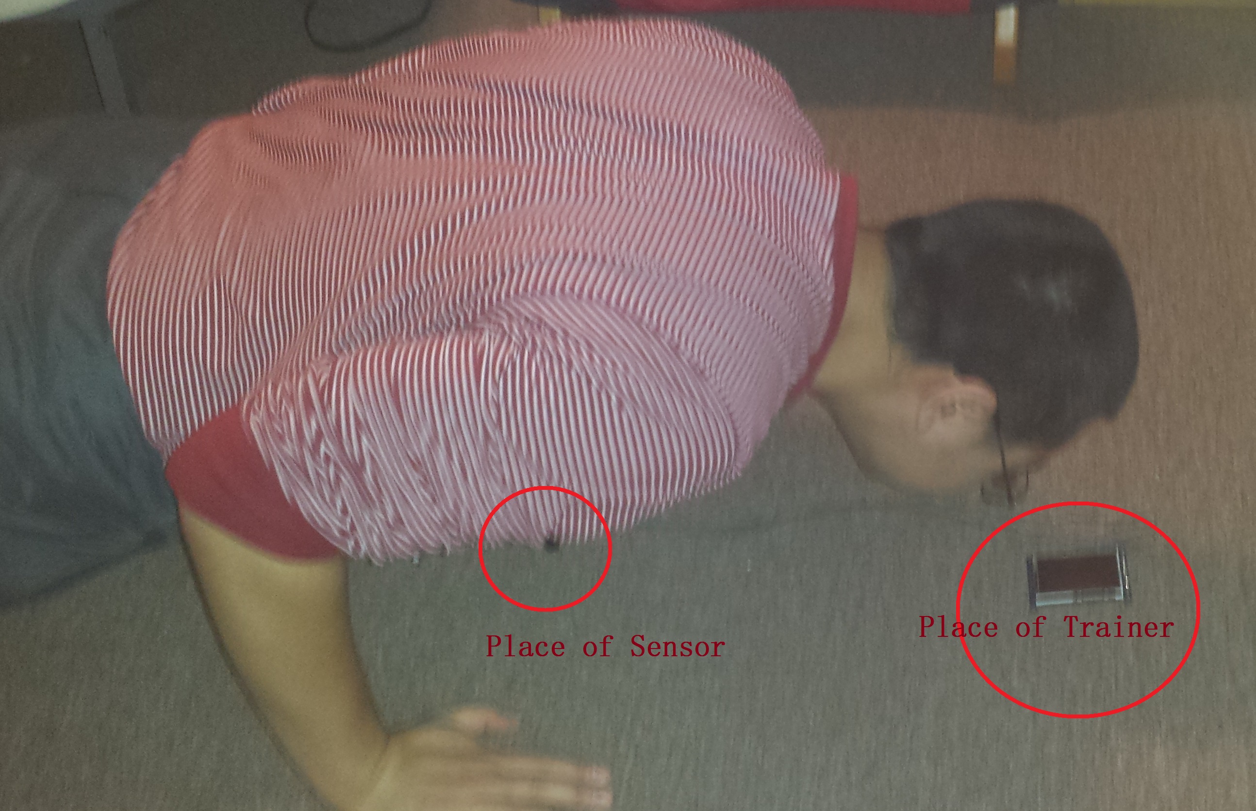
Practical Demo Image
For our ECE 4760 final project, we choose to develop an electronic push-up trainer that could monitor people's movement, provide training package to optimize their push-up exercise and body health. A distance meter will be used to figure out whether the posture of the person is correct or not, and the touch screen used will be either an input and output device. It will take command and push-up input from user and display corresponding information. All I/O messages are processed by the Atmel micro-controller. There will be three modes of operation. They are easy mode (for beginners, have less number of sets and less push-ups each set), hard mode (for intermediate/veterans, have heavy number of sets and more push-ups each set), and record beating mode (for fun, will keep the maximum number of push-ups made in eeprom). This design will be totally safe for human with its low voltage electronics and interface fits all people group. Moreover, this project is not an available product in market. Thus, it will not violate any intellectual property. The goal for this project is to learn to how to use complex color LCD, resistive touch overlay and ADC.
High-Level Design top
Rational and Inspiration
Health is important to human and push-up is an efficient way to exercise body and build body shapes. However, due to busy life-style and lack knowledge about physical exercise, a lot of people ignore daily exercises including push-up and their body movements are not proper. We come up with this idea because we find out that busy periods, such as before exams, we tend to ignore daily physical training and the body condition will simply keep getting worse and worse after exams. We thought that if there will be some “fun” device that can supervise people to do some daily work out, people would enjoy physical trainings. We choose push-up as one target training because it requires little space and is easy and efficient.
The motivation for this project was that such an electronic trainer would not only be helpful for one kind of training. In fact, it can be extended to more functionality such as a sit-up trainer etc. The combination of a MCU, touch screen and sensor system can satisfy needs for many kinds of in home physical training. The hope for this project is to implement the push-up ability. We have also note that there are past ECE 4760 project groups that have used touch-screen LCDs that can be used as reference. We will reference some hardware and software design to make the push-up trainer design more feasible, elegant, and easy to expand functionalities for further extensions.
High-Level Block Diagram
The high-level design will include four parts. They are user input, microcontroller unit (MCU), LCD display and sensor. User inputs will be taken by the touch screen LCD and the sensor system. And the touch screen and the sensor system will interact with the MCU.
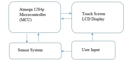
Figure 1. High Level Design of Final Project
1. Microcontroller: The microcontroller used for this project is Atmel Atmega 1284p, which is used in the ECE 4760 course. This controller has 32 general purpose input and output pins, where PORTB and PORTD pin sets will be used to handle the touch screen LCD. The PORTA set will be used as ADC to take sensor information and some of them will also be used for power switch and debugging purpose. In addition, the ECE 4760 course Atmega development board provides build-in USB interface for debugging that uses PORTD. Thus, PORTD 0 and 1 will be left untouched.
2. Touch Screen LCD: The Touch Screen LCD used in this project is suggested by Bruce Land. The ILI 9325 touch screen breakout board from Adafruit is used. Partial hardware and software setup will be referenced to previous project (Virtuoso: A Touchscreen Music App) for LCD display purpose. The touch part is implemented by using a resistive touch overlay. Thus, different voltage information will be fed into the microcontroller when various places are touched. Further breakout for the touch screen LCD will be shown in hardware design.
3. Sensors: We will use analog distance meter to measure whether the back of body is low enough when doing push-up, so that more muscle of body can be exercised and the purpose of this trainer is to monitor whether people’s physical movement is correct or not. The sensor will use infrared ray and take the reflection time of object to provide distance information.
4. User Input: User will use the touch screen by hand touching to select the desired training mode. (easy/hard/record) And when doing push-ups, user will need to use to nose to touch the designated circle region displayed by the LCD and keep back at a desired low position to achieve a successful push-up. Moreover, the user will also be able to choose other command prompted by the LCD by touching it.
Relevant Standards
Since IR distance sensing tools are used, it should follow exactly IEC/EN 60825-1 optical radiation standard to ensure safety for users, which should be implemented by the manufacture and the design group is responsible to verify it.
Hardware Design top
Overview
From the high level diagram, it can be seen that connections must be built between the MCU circuit, touch screen LCD circuit and the sensor. Sections below will explain them in details. All connections are verified by both user manual provided by manufacture website and experiment.
ILI 9325 Touch Screen
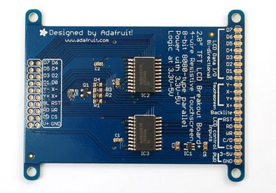
Figure 2. Touch Screen Photo and Connection Diagram
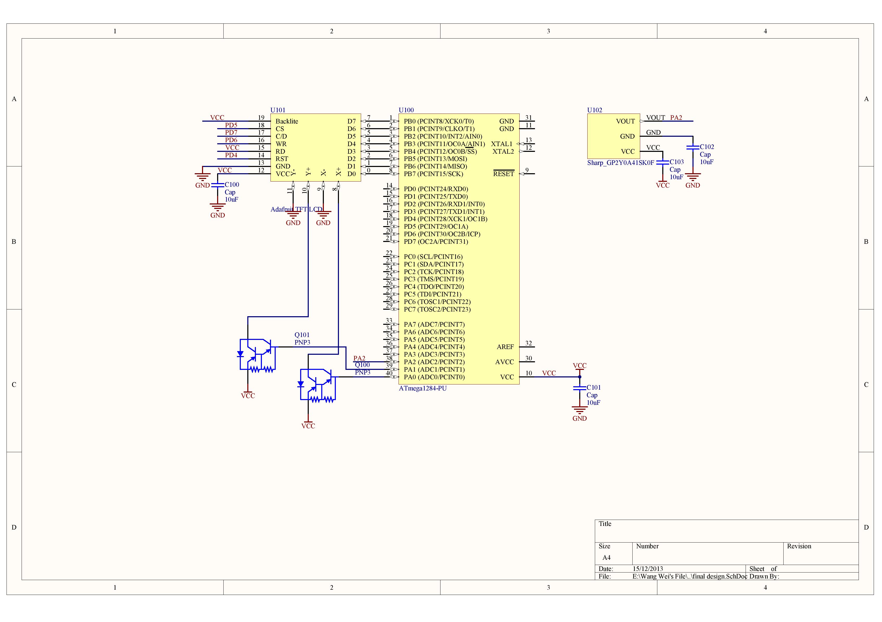
The figure above shows the pin-out of the ILI 9325 touch screen breakout board from Adafruit. This LCD is a 2.8 inches TFT LCD screen that is connected to ILI 9325 controller chip, which is a 18 bit 262k, 240x320 resolution, and 172800 RAM one-chip SoC driver for a-TFT LCD driver. However, only half of the colour complexity is used in this breakout version that will make the programming and connection for LCD easier (D17-D0 are available, but only D7-D0 are used in this project). The D0-D7 pins are connected to the PORTA0-7 of the MCU. These pins are the LCD data pins that will take input data from microcontroller and send it to the ILI 9325 colour LCD controller so that proper image can be shown on the LCD. On the other hand, RST, RD, WR, C/D and CS pins are connected to PORTD’s of the microcontroller for LCD input control purpose so that the ILI 9325 knows when to take the input and what the desired input is. Backlite pin of LCD is connected to 5V from the MCU to light up the LCD screen. The Y-/+ and X-/+ are the analog output of the resistive touch overlay on top on the LCD screen. Both X- and Y- are always connected to ground because they are used for negative input only. When Y+ is connected to 5VDC, a varying voltage indicating the x-position can be read from the X+ pin. Similarly, y-position can be determined when X+ is applied with 5VDC. To achieve this, two TIP 125 PNP Darlington transistors are used as switches to open and close the connection between X/Y+ to 5V. The Collector is connected to 5VDC, base is connected to a digital output port (PORTA 6/7 used), and the emitter is connected to either X+ or Y+. This connection ensures that when base is high (5VDC), the collector and emitter channel is shut down. And when base is low, the channel is open and 5VDC is fed to either X+ or Y+. At the meantime, we read the pin that is not being supplied with 5VDC through ADC pins of microcontroller. Analog circuit diagram of the transistor is shown below. In the end, the 3-5V and GND is connected to the power and ground for power supply purpose.
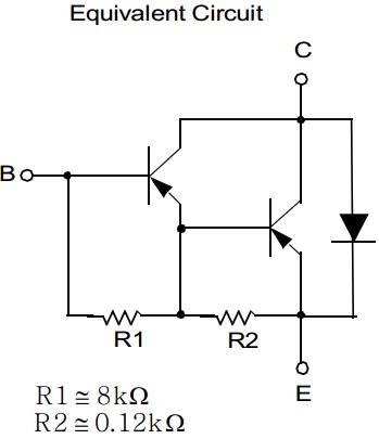
Figure 3. TIP125 PNP Darlington Transistor Equivalent Circuit
Sharp Distance Meter
Model GP2Y0A41S0F Sharp analog output distance measuring sensor is used in this project to take measurement of body movement. It is capable of measuring distance from 4 to 30 cm, with an operation voltage of 5VDC and current of 12mA. The block diagram of the sensor is shown below.
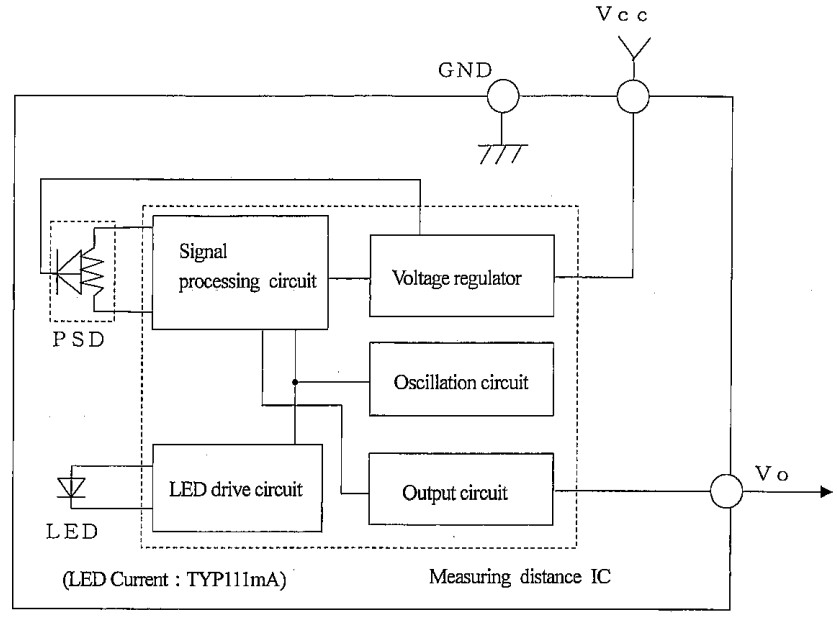
Figure 4. Sharp distance measuring sensor schematic
This sensor takes 4.5 to 5.5 VDC input and outputs the analog distance information in voltage from the Vo pin. It has a 5.0 ms maximum time delay from measurement to output that should be considered when running the while(1) loop in main. The connection is relatively simple that the VCC/GND corresponds to 5V and ground of the MCU circuit and the Vo is connected to PORTA2, which is an pre-defined to take analog input. In addition, since sensors are active elements, capacitors to low pass the power are applied. Thus, additional noises can be eliminated. Without these low pass capacitors (10uF), the microcontroller will randomly resets due to expected ground noise on the MCU circuit.
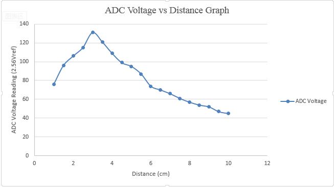
Figure 5. Voltage vs. Distance graph
Moreover, another important factor lead to the choice of this sensor is the low current rating. This sensor requires only 12mA to operate, which is less than the nominal current (about 20mA) of the Atmel Atmega 1284p microcontroller. Previously, we have used another Sharp distance sensor that could measure long distance but with 70mA current rating. And that sensor will cause the microcontroller to reset periodically. To eliminate those hazards, we focused on low current requirement sensors and we finally determined to use the GP2Y0A41S0F Sharp analog output distance measuring sensor.
Microcontroller
In our final design project, we used the ECE 4760 development board with Atmega 1284p microcontroller. The circuit board provides USB interface that will allow easy on chip debug. On the other hand PORTA/B/C/D are all connected to required pins listed in previous sections and all connections will simply use bread board and wires available in lab. The picture below represents the all the elements that are used in this project. Detailed schematics are shown in the appendix.
Software Design top
The programs for the microcontrollers are implemented in C. The compiler is WINAVR GCC C compiler and uses WinAvr 20100110 libraries, which contains necessary for general purpose input and output (GPIO) and also essential interrupt service routine (ISR). The editing environment is AVR Studio version 4.19, which is suggested by the course. The software design in this project will primarily involves three parts. ADC configuration, video library for the LCD and state machine design to switch between different modes.
ADC Code Design
The ADC related functions are implemented in touch.h. The get_touch() will take run the ADC for touch screen and the get_distance() will work for the distance meter. To begin with, the ADC will be initialized with ADMUX=(1<<ADLAR)|(1<<REFS0)|(1<<REFS1); ADCSRA=0x07; ADCSRA|=(1<<ADEN)|(1<<ADSC);. The internal 2.56V is set as voltage reference by the REFS0 and REFS1. We choose the 2.56V as reference after testing the maximum voltage output from either the touch screen or the distance meter and then find 2.56V is a feasible voltage reference value. The ADLAR=1 will make the high bits of ADC is representative. The most useful ADC values are stored in the 8 bit ADCH register. In addition, ADCH must be read before ADCL, which is the low bit registers. If read happens in the reverse order, the ADC system will be locked and no long works until reset or power off. The ADCSRA=0x07 is a divider that makes the ADC’s running clock matches with requirement about 125kHz. ADEN will simply enable the ADC and the ADSC will tell the ADC whether to start the conversion or not.
After the ADC initialization, we need to select different MUX number of ADMUX. For the get_touch() function, we first choose the ADMUX=(1<<ADLAR)|(1<<REFS0)|(1<<REFS1)| (1<<MUX0); so that PORTA1 is selected to be the ADC input. Then the ADCSRA|=(1<<ADSC); while(ADCSRA&(1<<ADSC)); will start the ADC and let it finish. After finishing, we can assign AY=ADCH so that we can start the x direction read. We did PORTA=0x80, output will trigger the BJT (connected as switch) to make Y+ pin 5VDC. Then we go through similar steps, we set MUX0=0, so that PORTA1 is selected to be the ADC input. When set the ADSC bit and wait for it to finish then record AX=ADCH. Then both X and Y direction information are all collected.
Furthermore, the get_distance() function also go through the same code sequence to obtain the voltage information from the sharp distance meter output pin. We connect the output to PORTA2, so we need to set the MUX1 of ADMUX equal to 1 when we perform the get_distance(). For debugging purpose, we have also added fprintf to each function so that we could observe the digital values after conversion. The figure below is a sample of the ADC putty screenshot.
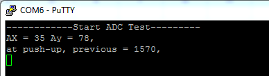
Figure 6. Putty Screenshot for ADC
Graphic Library Design
In this project design, we took the advantage of previous designs about graphic functions to display message and draw images to the touch screen LCD. The design group for reference is named in the acknowledgement. To learn how to achieve the desired graphic images, we spend time on studying the previous libraries and the LCD controller and data lines. The following paragraphs will explain the LCD related header files.
lcd.h – This is the core of LCD display program. It also includes another header called character.h, which is used for letter display and will be explained later. There are three basic primary functions of this header. The first one is LCD_Writ_Bus(char VH,char VL). It will write value to the LCD bus. 8 bit VH will be send first and 8 bit VL will be send later. LCD write pin on the TFT LCD will be turned on during transmission and is switched off later. The other two important functions are LCD_Write_COM(char VH,char VL) and LCD_Write_DATA(char VH,char VL). They both call the LCD_Writ_Bus function. However, the write_com will turn the LCD RS pin low while write_data will turn it high. This is implemented by instruction from ILI 9325 instruction manual. After implementing these three basic functions, we can then start building more complex functions.
To draw a pixel on the TFT LCD, we have to know the x/y location and colour. draw_pixel (unsigned int x, unsigned int y, unsigned int color) is implemented such that we prepare the data first, loaded them desire register indicated by the ILI 9325 manual. Then we turned on the LCD CS pin so that it is displayed. With this concept, we can then try libraries that will draw rectangular shapes, circular shapes, and colour bars etc.
With the capability of drawing different images, then we can build our own planes for mode display. Functions such as welcome_page(),draw_trainer(),draw_trainer_imm(), and etc. are accomplished to draw the user interface for different modes or other images for information display purpose only. In addition, function of showcharacterstr(unsigned int x,unsigned int y,unsigned char *str,unsigned int dcolor,unsigned int bgcolor) is used to display letters. This function is also designed by previous lab group and it uses the character.h to determine the display pixels for different characters.
The hardest part of this LCD header is the LCD_Init() function. It is used to initialize the 2.8inch TFT touch screen LCD. After studying through the ILI9325 manual and the code design from previous project group, we determined to reference their design because it follows all required register value assign on both the manual and also the sample library provided by Adafruit. Unfortunately, the Adafruit provides codes only for Adriano version and is very hard to convert to Atmel chips. However, it can also be used as a good reference code design book for error checking and debugging.
character.h – This is the library provided by previous project groups who designed a touch screen musical device. This library is used to display characters that can be found in ASCII table. With the help of this library, the implementation of message display becomes easier. The library will present letters in white colour with black background. To make the interface looks more user-friendly, we have to be careful about modifying the background paint when displaying message. In addition, all display images will be demonstrated in the result section. The image below shows voltage switch for the X+/Y+ pin from the TIP125 BJT.
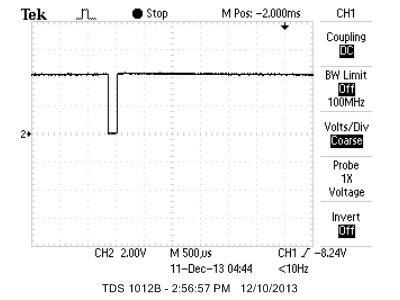
Figure 7. BJT switch oscilloscope screenshot
Uart Code
Uart data transmission is directly used from ECE 4760 website. This is used for only debugging purpose but is extremely helpful throughout the code design. Files that are used in the project are uart.c and uart.h. They are directly available for ECE 4760 lab webpages. With the successful uart library, we are able to obtain putty screen shot for debugging purpose.
State Machine Code Design
A trainer will contain a lot of functions and features. Thus, it will need to switch between different modes and display corresponding messages and graphics. Thus, there are totally of two state machines that are designed in this project. They are the draw_next() function in lcd.h and debounce() in touch.h.
The draw_next() is used to switch between different display images. The code design is relatively simple. Each case will be responsible for drawing the graphic for different modes. Thus, the cases under the switch function are the names of different modes, such as main page, push up and etc. In each case, there will be a delay to settle down the image, we set it to 500ms. And then the new image will be drawn. This function is called in initialization and debounce state machine to draw the next image.
The debounce() function is similar to lab 2 of fall 2013 ECE 4760. It takes input of the touch screen to determine what the next mode is or perform desired actions. There will be totally of four states. They are NoPush, MaybePush, Pushed, and MaybeNoPush. System starts from NoPush state. Any input from the touch screen will trigger the state going from NoPush to MaybePush. We take a previous value in NoPush and compare it to current input at MaybePush. If they equal, then we know it is a push and state goes to Pushed. When releasing from touch screen, we change the state to MaybeNoPush and verify the release again. All actions are taken after release. Thus, the code for MaybeNoPush class is far more complex than others. This state machine will be responsible for determine actions according to input. Under different modes such as mainpage and pushup, the action with push locations will be different. Thus, flags are used to deter what to do at MaybeNoPush case. Thus, this is also a mini state machine within the MaybeNoPush case. For example, under pushup mode, if I pressed the exit region, then flag 3 will be set and in flag 3, mainpage will be drawn after few delays. In general, the debounce() is a finite state machine checking touch screen press but also contains a mini state machine to determine what action to do.
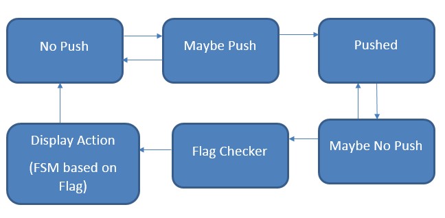
Figure 8. Debounce State Machine Flow Diagram
Main program
The main.c file puts everything together to run tasks in a predefined schedule, and the init.h file simply links all functions together and does the initialization for all necessary ports and interrupts.
init.h – It contains two timer ISR and one GPIO initialization. Timer0 ISR is used for count the time interval between tasks that runs in while (1) loop in main. For our program, we make all tasks run every 50ms. TCCR0A= (1<<WGM01) will turn on the compare and match interrupt, TCCR0B=0x02 sets the pre-scalar and OCR0A=249 the compare value. Thus, very interrupt happens 1/16Mx250x64 = 1ms. A counter of 50 is decremented in the ISR so that 50ms count is implemented. Similarly, we initialize the timer1 too and let it count for about 15 seconds to implement the rest function between different sets of push-ups. The GPIO_init() will also initialize uart transmission for debugging purpose and set initial states for all state machine. Global interrupt enable, set(), is also called in this initialization.
Moreover, the GPIO_init also initialize the record number for record beat mode by checking the value of eeprom. if (eeprom_read_byte((uint8_t*)eeprom_true) != 'T'){eeprom_write_byte ((uint8_t*)eeprom_true,'T');eeprom_write_word((uint16_t*)eeprom_record,0);}else{old_record=eeprom_read _word((uint16_t*)eeprom_record);} These lines will check whether the record check mark, eeprom_true is written or not. If not, we set the record to 0. If yes, we take load the old record from eeprom so that user information is reproduced.
Result top
LCD Performance
The LCD designed for this lab successfully meets the requirement for display. According to the state machine for draw_next(), all pictures of different modes have been taken and pictures below shows all beautiful mode screens.
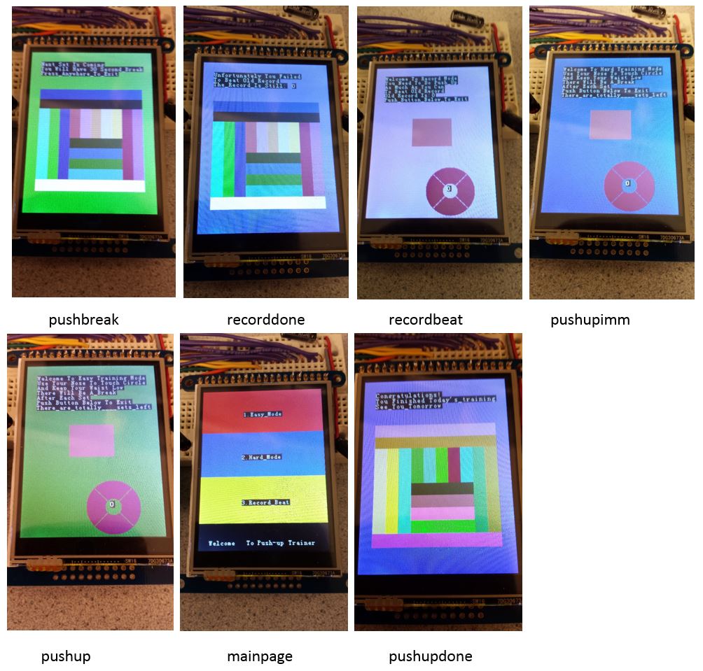
Figure 9. LCD image demonstration
Touch Screen Performance
Unexpected performance of the touch screen overlay happens in this hardware design that the analog X+ and Y+ have dependency between each other. Even though both X and Y’s analog values increases with the corresponding direction, the interference from other axis cannot be ignored. The problem is due to the nature of resistive touch screen. A detailed ADC value distribution diagram is shown below. From those values, it can be seen that there exists potential hazard of clicking one region of the LCD but the software will misunderstood it to other region. Thus, instructions should be given to users that any push of the touch screen should try stick with middle region and with moderate force to touch. That is because a slight touch of bottom will generate a voltage equal to a hard touch in middle. These non-idealities add up the complexity of the project and users are restricted to touch certain region with moderate force.
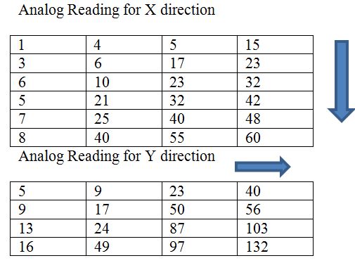
Figure 10. ADC value distribution
Distance Meter Performance
At the beginning, we have chosen a distance meter capable of measuring 1.5m long. Such a sensor will require 70mA current on a single port of Atmega 1284p, which is far more than the nominal running current of 20-35mA. Thus, the system will reboot periodically if this sensor is used. Then we switched to another Sharp distance meter that has only 12mA current rating and is capable to measure 30cm. Even though the distance is much less, the requirement distance for pushup (usually 5cm to 25cm) can also be met. In the end, our group decides to use this sensor other than the previous one. The distance vs. voltage diagram is already shown in hardware design section that the sensor works as expected.
Circuit Modification
The desired circuit would not contain the TIP BJT switch because the initial choice of touch screen LCD will have SPI interface that will transfer the touch information after proceed by a touch overlay controller. However, due to the version different of touch screen LCD, we have to change our initial circuit design to make it capable of reading analog value and output 5V alternatively at mean time.
In addition to additional switch circuit, we also realize that we need low pass filters for power. We put several 10uF capacitors between VCC and GND to eliminate noise injected to ground. Noise is mainly generated by the distance meter. Any active element, including distance meters, will potentially generate huge noise. Case becomes obvious for our design that if there is no such filter, the microcontroller resets randomly due to the high level of noise caused by the sensor. Microcontroller only works stable with these capacitors connected. After making all these modifications to initial hardware design, we are able to accomplish the desired tasks. Picture below shows the result of this project design.
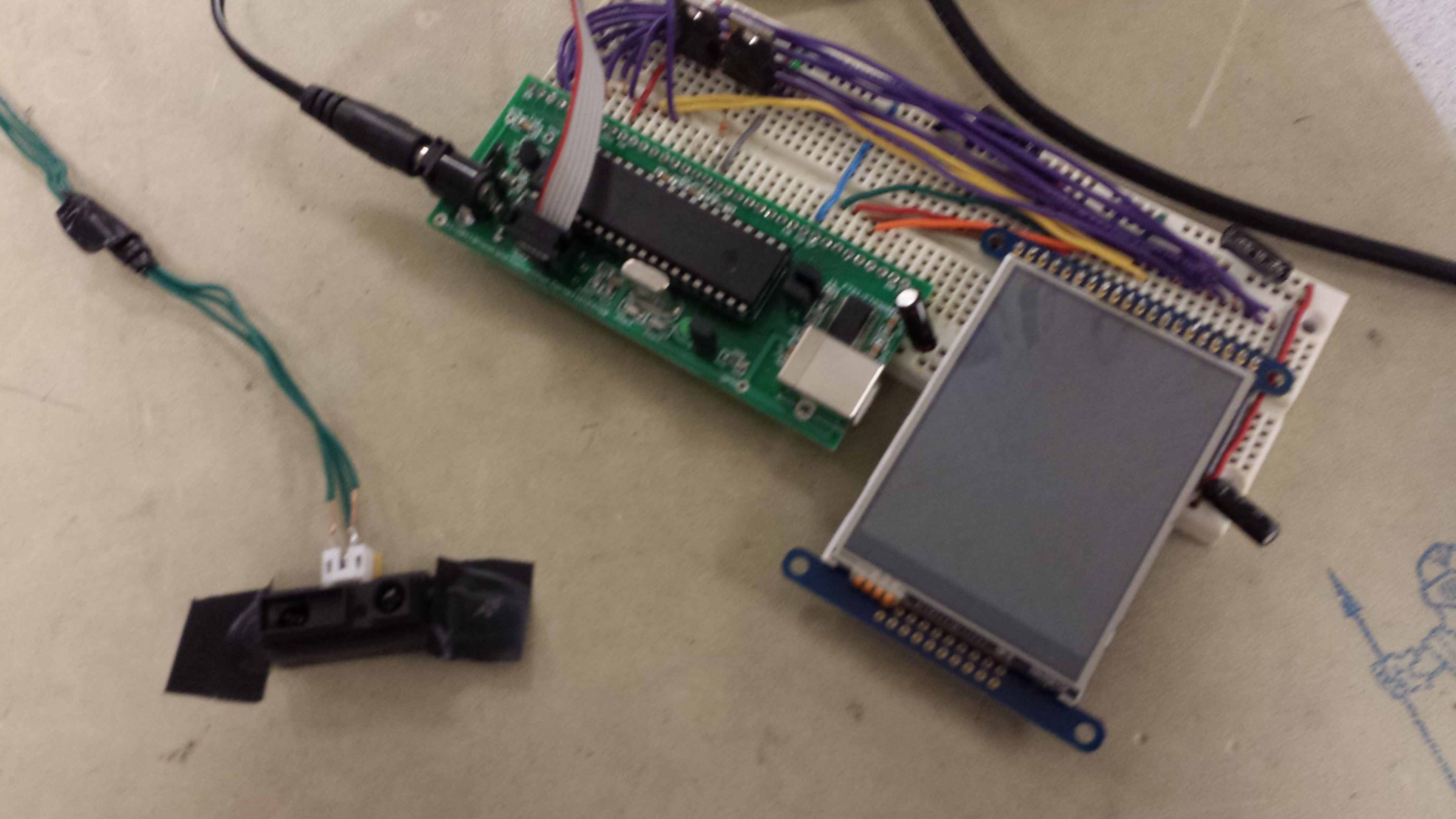
Figure 11. Final Circuit Connection Photo
Conclusion top
Summary of results
According to previous analysis and result demonstration, it can be seen that the expectation of our project is met. In our project proposal, we stated that we want to design a trainer that helps people to do pushups correctly with interesting features to attract users. In our implementation, we build up 3 modes targeting for different user group. And the sensing method we use could successfully monitor people to perform push-ups correctly. The distance meter is proved to meet the safety standard and outputs desired analog voltage. The LCD is connected correctly that both the graphic and touch screen parts works well. Necessary circuit modifications make hardware feasible in the end. On the other hand, even though the code design is intensive and the finite state machines are tricky to design, through efforts, we successfully make the switch between different modes and graphic images running smoothly. When starting this project design, we are frustrating about choice about touch screen LCD, hardware connections and feasibility of codes. As the project progresses, various problems about microcontroller, pin I/O configurations haven shown up. We accumulate more knowledge about microcontroller design during these configuring and debugging steps. This incremental project design progress has also taught us a good lesson about the engineering design flow, which is also essential for future projects.
In general, the device we designed qualifies its name for being a push-up trainer. All hardware and software are successful through lots of re-design and debugging mentioned in previous parts. However, there is still potential to add more interesting features that will help the efficiency of the training at the mean time. Those will be explained in the following section.
Possible future work
As mentioned previously in this software and hardware design, the most unsatisfactory part is the touch screen LCD. The weight function to calculate the position pressed cannot guarantee 100% correctness about determines the X and Y location. A LCD with touch controller will perform much better because the output is digital and there will not be any ambiguity about different position touches. To improve the design for this project, choosing another LCD with better touch screen control will be the primary task.
As mentioned previously in this software and hardware design, the most unsatisfactory part is the touch screen LCD. The weight function to calculate the position pressed cannot guarantee 100% correctness about determines the X and Y location. A LCD with touch controller will perform much better because the output is digital and there will not be any ambiguity about different position touches. To improve the design for this project, choosing another LCD with better touch screen control will be the primary task.
Ethical Consideration
This project is highly related to people’s daily life. A push-up trainer will be feasible to all person groups. Thus, we carefully abide IEEE Code of Ethics. Even though all electronics are low power and relatively safe for operation, we still pay attentions to ensure that the project design is safe enough. For example, we double check the IR distance meter used in this project to meet safety standard. Throughout this project, we consistently think about applying learned knowledge about microcontroller to real world. Our target is to improve people’s health by creating helpful electronics applied to physical trainings. Thus, our idea and process of the project design is coherent with high level demand of IEEE Code of Ethics. We have also ensured that all related persons and previous works are properly cited. Furthermore, we welcome any forms of contact about project design hazards and problems. In the end, we worked well as a team throughout the semester and we thank ECE 4760 course that leads to the successful design of this project.
Legal Consideration
According to all hardware and software design, potential violation for this project may include using Adafruit LCD module directly and library codes from both Adafruit and previous project work. Besides, there is no other concern about legal consideration. There is no similar product that is commercially off-the-shelf.
Appendices top
A. Source code:
B. Schematics:
C. Bill of Materials:
| Part | Part Number | Source | unit Price | Quantity | Total Price |
| Touch Screen LCD | ILI9325 | Adafruit | 40 | 1 | 40 |
| Sharp Distance Meter | GP2Y0A41SK0F | Digikey | 7.4 | 1 | 7.4 |
| BJTs | TIP125 | Lab | 0 | 2 | 0 |
| Capacitors | 10uF | Lab | 5 | 0 | 0 |
| Wires | 16AWG | Lab | 0 | 20 | 0 |
| Bread Board | Lab | 0 | 1 | 0 | |
| Atmel Development Board | ECE 4760 | Lab | 5 | 1 | 5 |
| Atmel Microcontroller | Atmega 1284p | Lab | 5 | 1 | 5 |
| Total Price | 57.4 |
D. References:
The website pages and datasheet below are used as reference to this project design.
Datasheet
Acknowledgement:
We would like to thank Bruce Land for his kindly helps about various guidance throughout this project, especially about the choice of touch screen LCD and distance meter. On the other hand, we would also like to thank previous group that is referenced on providing instructive work on building graphic library.