Looping Piano Synthesizer
an intuitive looping tool for the casual musician

Sam Dickerman & Brian Chen
an intuitive looping tool for the casual musician
What can’t our looping piano synthesizer do?
From features like octave and tempo control to quick recording and an easy-to-read help menu, our looping piano synthesizer is simple and easy to use. The goal of our final project was to incorporate the skills we learned in the various labs while still having fun working on something we love. Since we are both musically inclined, the answer seemed simple: making a synthesizer to feed our passion for engineering and music.
The motivation for our project was to improve on conventional loop pedals / synthesizers in three main ways: eliminate unnecessary and seldom-used features, make the looping feature as intuitive as possible, and achieve this at a much lower cost than professional loop pedals. Considering high-end synthesizers cost in the $1000's of dollars and all we had to work with was less than $100, we aimed to create a keyboard with basic synthesizer features.
Overall, this project had 6 things to accomplish from an implementation perspective.
1. Synthesis of correct sine waves at certain frequencies
2. Scanning the push buttons for presses
3. Implementing the command with said push button
4. Managing the state machines
5. Recording the track
6. Updating with TFT display
We generated sound waves with direct digital synthesis. This means that we created a table of evenly-spaced sine values and then sent values from it to a digital-to-analog converter at a constant sampling rate. By using the equation increment = Fout*(2^32)/64000 (since 64000 Hz is our sampling rate) we made an array of frequencies from C2 to B5 to select from:
| C2 8778846 |
C#/Db2 9300618 |
D2 9853595 |
D#/Eb2 10439790 |
E2 11060548 |
F2 11718214 |
F#/Gb2 12414804 |
G2 13153338 |
G#/Ab2 13935156 |
A2 14763950 |
A#/Bb2 15641734 |
B2 16571863 |
| C3 17557692 |
C#/Db3 18601235 |
D3 19707189 |
D#/Eb3 20879581 |
E3 22121095 |
F3 23436429 |
F#/Gb3 24829609 |
G3 26306675 |
G#/Ab3 27870311 |
A3 29527900 |
A#/Bb3 31283468 |
B3 33143726 |
| C4 35115384 |
C#/Db4 37202470 |
D4 39414378 |
D#/Eb4 41759162 |
E4 46872858 |
F4 23436429 |
F#/Gb4 49659218 |
G4 52613350 |
G#/Ab4 55740622 |
A4 59058800 |
A#/Bb4 62566936 |
B4 66287452 |
| C5 70230768 |
C#/Db5 74404940 |
D5 78828756 |
D#/Eb5 83518324 |
E5 88484380 |
F5 93745716 |
F#/Gb5 99318436 |
G5 105226700 |
G#/Ab5 111481244 |
A5 118117600 |
A#/Bb5 125133872 |
B5 132574904 |
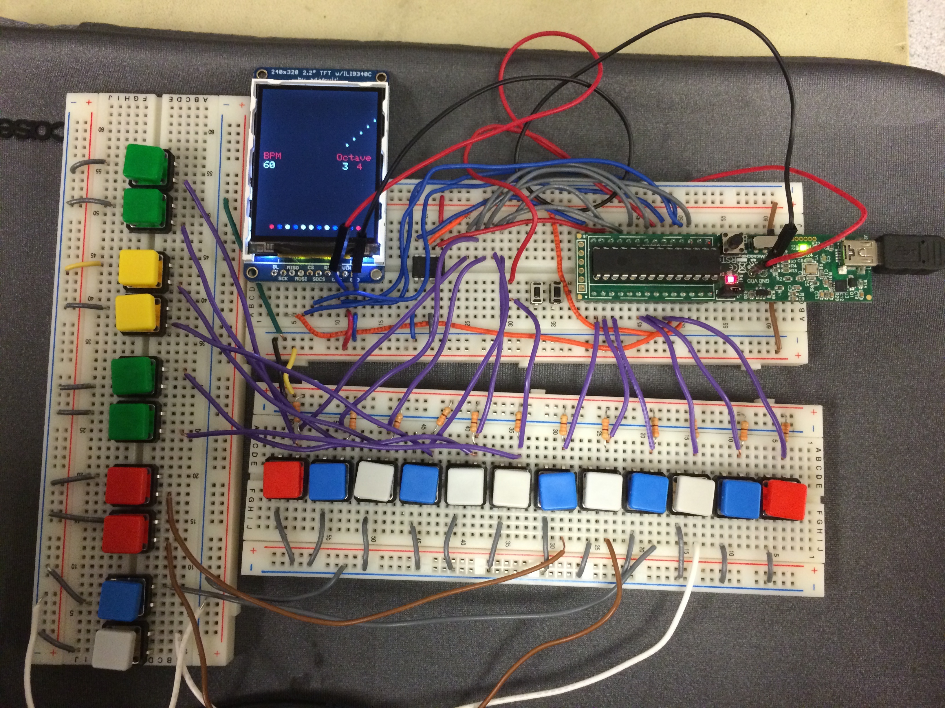
Since we only had 12 available pins on the PIC32 we were forced to make double buttons act as one button. In other words, when pushing down two keys, this acted as a different command for the PIC to read. For aesthetic appeal, we wired pairs of buttons in parallel to the keybaord on a different bread board to act as auxiliary buttons. So if you were to press say C and C# at the same time that would correspond to a certain function on the auxiliary board. Thus, this limits us to only being able to push one key at a time.
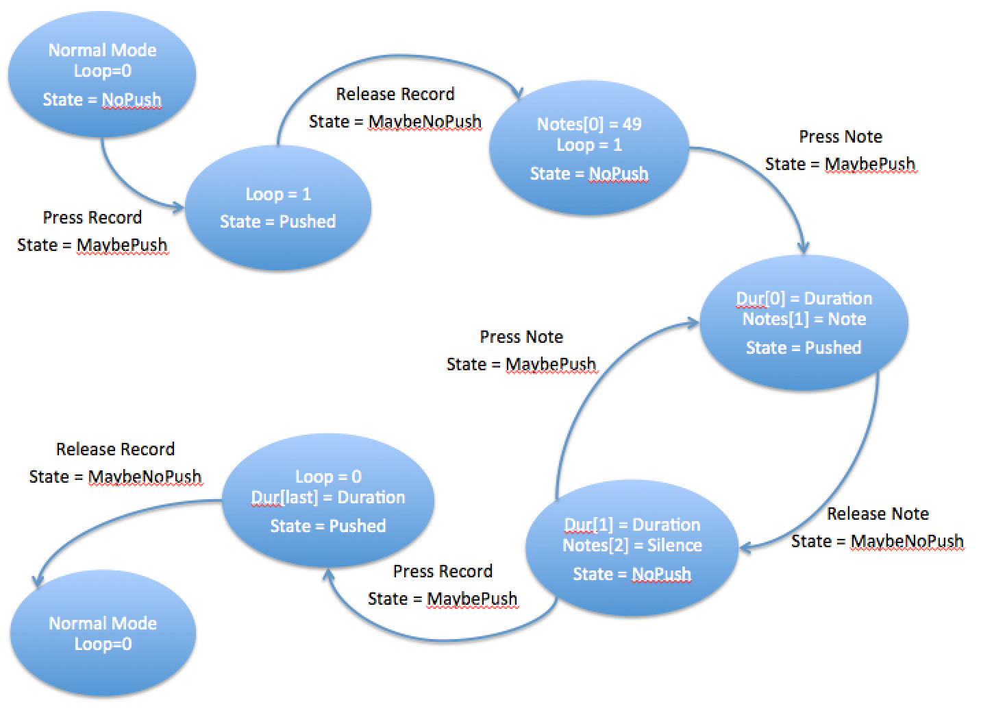
Recording and looping the track created by the user was a bit more complex. We decided that we want to keep each note and its duration in two seperate arrays. This makes it easy to keep track of both the what note was played and how long it was played before. It is also important to remember that silence is a note. All the notes ranging from C2 to B5 are encoded to be values 0 to 49 respectively. In the code below we hard coded silence to be value 49.
As for actually playing the notes this occured in the ISR. The ISR is triggerd by a timer which we wanted to sample at 64kHz with a CPU clock of 40MHz, meaning our toggle rate of the timer is 625. We sampled at 64kHz to ensure our resolution for the DDS was clear enough to hear.
Debouncing Push Buttons FSM
Our device reads the input pins and then translates them into a code that we set. There are two input variables, A and B, and each input pins refers to a certain bit within the A or B. We set it up so that when a bit is high, that means that the button is not being pushed. We bitwise-OR the bits that we are reading into a scanning variable. For example, if BIT_0 and BIT_2 are the only bits that are low, out of say BIT_0, BIT_1, and BIT_2 then our scanning variable will read "4". That is (2^0 + 2^1 + 2^2) - (2^0 + 2^2). In our case we have 12 pins where each key is connected to a different bit.
Our FSM demonstates how we decide when and what values of notes to store into the arrays loopdur and loopnote. It made most sense to enter loop mode as soon as the corresponding button was pushed down. As soon as the loop button was released, "silence" would be recorded into the loopnote array and its duration would be recorded the instant the first note was played. While the next note is being pushed down, the duration of the previous note is recorded and the next key is stored. This continues until the user pressed the record button again to stop. As the user is pushing down the record button the duration of silence is stored into its respective array.
Our various features include tempo control, octave control, looping, and a visual metronome. In order for the metronome to tick back and forth in a circlular motion, we calculated the sine and cosine of multiple dots to simulate a wand ticking back and forth. As for the tempo control, we selected a minimum and maximum bpm to be 20 and 200 respectively. The bpm can only be changed in increments of 5.
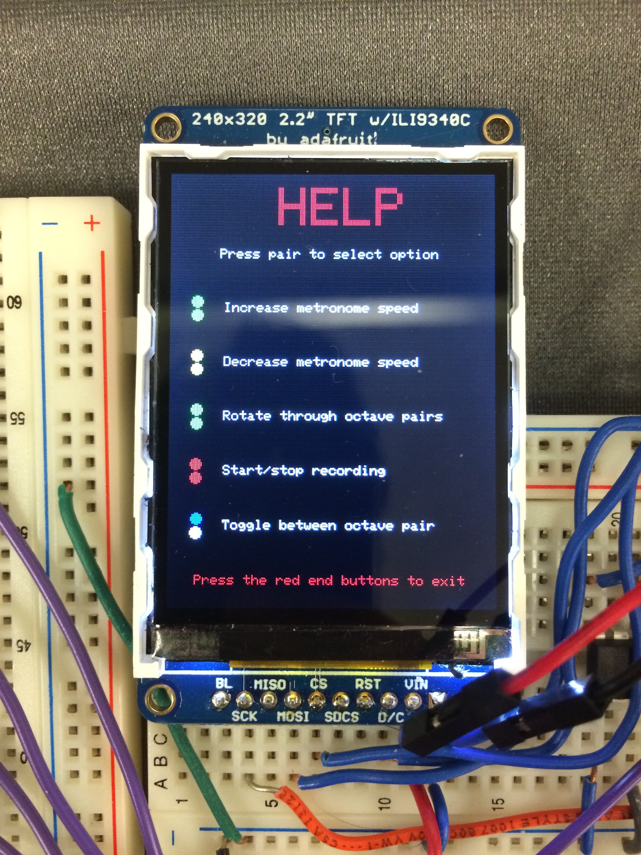
It was easy to update the TFT display since Syed Tamid Mahbub wrote all the functions to write words and shapes of all different sizes. Clearing the TFT was as easy as writing a black rectangle to cover the screen. Our color-coded help menu also made it easy for users to use our device.In order to enter and exit help mode, the user pushes the two end red buttons on the keyboard. As shown in the results section, the top two green buttons pushed together at the same increased the tempo, while the two yellow below it decreased the tempo 5 BPM at a time. The two middle green buttons rotated through a given octave pair. The two red buttons below that is the record command. Lastly, the blue and white button pair toggled between octaves in a given octave pair. We had two buttons to change the octave because we wanted the user to be able to change the octave quickly in a song. This means that our piano realistically only ranged between two octaves during any given recording. This implemented so the user could record the harmony then play the melody over top of that. The user is also not capable of pushing any keys or making any noise while in the help menu, nor able to enter help mode while in recording mode.
In the ISR, we handled the generation of values to send to the DAC for DDS. If play == 0, that means no button is being pressed so we would not do anything. If play == 1, that means a button had been pressed, so we should begin DDS and also linearly ramp up the signal to maximum amplitude. Since the signal had been set by the keypad protothread, we use it as an index of the increment table. This allows us to select the frequency we want to DDS. Then, we right-shift the two accumulators by 24 to obtain only the 8 most significant bits, and use it as an index to the sine table. In order to accomplish ramping, we generated a ramp_table, which contains 320 evenly spaced float values between 0 and 1. Since we sample at 64 kHz, having 320 ramp values means that it will take 5ms to go through the ramp table. We figured 5ms was long enough to ramp our note. If play == 1, meaning we are in the ramp-up stage, we multiplied the summed sine_table values by a value in the ramp_table and then increment the ramp_table index. Then, we add 2047 to this value (so that it is between 0 and 4096 instead of -2047 and 2047), and send it to the DAC. If we reach a ramp table index of 320, then we set play = 2, which indicates steady playback mode (no multiplying by a ramp_table value). Upon a key release, the keypad thread sets play = 3, so we ramp down by going backwards through the ramp_table and multiplying the signal by those values accordingly. When we reach index 0 of the ramp table, we set play = 0, which means no more sound is playing.
| Note | Accepted Frequency | Observed Frequency | % Error |
| C | 261.1 | 261.8 | 0.27% |
| C#/Db | 277.2 | 277.8 | 0.22% |
| D | 293.7 | 294.1 | 0.14% |
| D#/Eb | 311.1 | 310.6 | 0.16% |
| Average % Error | 0.20% |
Even though all the sounds were made digitally, we were impressed by the accuracy of our notes created through Direct Digital Synthesis. We expected to sample sounds from a guitar, drums, and a real piano to have a total of 4 instruments at the end, but we were not able to meet those expectations. On the other hand, we exceeded our expectation in terms of aesthetic appeal and ease of use considering all we had to work with were push buttons. If we had found a small child's keyboard online we would have used that instead of the push buttons that we used to simulate a keyboard. For now we only made 1 track recordable and the ability to play over that track in normal mode, but we could have easily applied this idea to multiple tracks.
We credit any code that we referenced from Bruce Land's Lab 2, Syed Tahmid Mahbub 12-bit DAC or TFT blog, and Adam Dunkels Protothreads.
We have considered the IEEE code of ethics when working on this project and find no conflict of interest, no events of bribery, treated all persons fairly and did not engage in acts of discrimination, avoided injuring others or their property, and accept responsibility in making decisions consistent with the safety, health, and welfare of the public. This project interested two college students wanting to have fun creating music for the world.
| Component | Vendor | Quantity | Unit Price |
| White Board | Lab Stock | 3 | $6 |
| Colorful Tactile Button Switches | Adafruit | 2 | $5.95 (per 15) |
| TFT Display 240x320 | Adafruit | 1 | $10 |
| PIC32MX 250F128B | Digikey | 1 | $5 |
| MCP4822 | Digikey | 1 | $1.07 |
| MicroStickII | Lab Stock | 1 | $10 |
| Resistors | Lab Stock | 12 (330ohms) | $0 |
| Wire | Lab Stock | 2 m | $0 |
| Total Cost | $43.97 |
PIC32 Peripheral Libraries for MPLAB C32 Compiler
Microstick II w/ PIC32MX2xx Pinout
Adafruit Tactile Square Buttons
We would like to thank and recognize Bruce Land for his outstanding guidance and expertise in one of the most hands-on courses at Cornell. We would also like to thank the TAs for their paitience and assistance with debugging and working with us to make sure we understood the material. In particular we feel that Shiva Rajagopal helped us most and would like to give him an honorable mention.