Introduction
Our project aims to create an un-intrusive movement tracking system that will be worn by a domesticated bird. The system will be capable of detecting and recording animal movements and body temperature and wirelessly reporting the collected data to a computer via Bluetooth. Bluetooth modules on different birds will also interact in order to detect distance between them. This technology provides avenues for accurately tracking the health or status of individual birds by deriving this from their movement and distance data. Potential applications include tracking the activity levels of a bird for comparison to other birds and monitoring social interactions between birds. Two prototypes of the system will be made, so that the social activities between 2 birds can be recorded and analyzed.
The device will be placed on the back of a chicken (we will look into best practice for keeping it in place). For the most part the module will rest on top of the feathers and be electrically isolated with a smooth plastic encasement. A thermocouple built into the IMU will be the only component continuously moving against the bird (aiming to be closer to the skin). Our end goal is to keep the prototype on the bird for approximately 30-45 minutes, however, testing it in 5 minute increments will be sufficient. We plan on measuring each occurrence of different movements, tracking temperature, and with two devices we will have proximity tracking between birds.
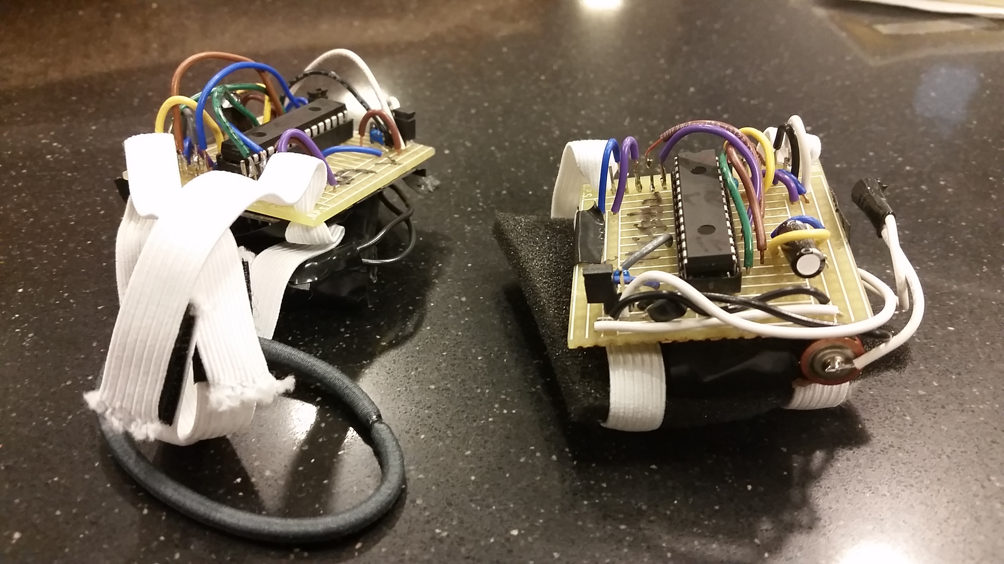
Figure 1: Finished versions of the poultry movement monitors (contains all necessary hardware, straps, velcro fasteners, and foam lining for chicken's comfort.
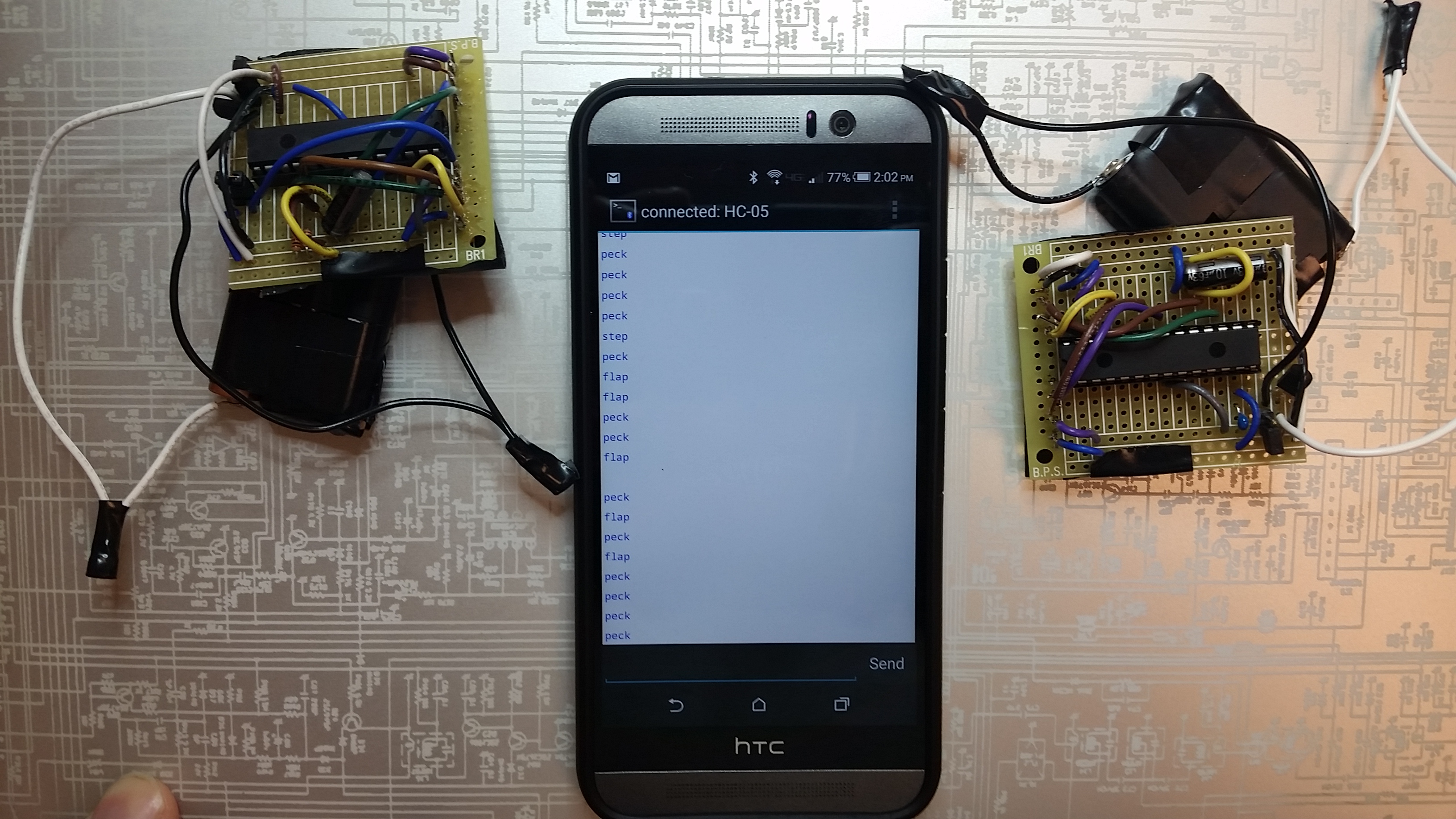
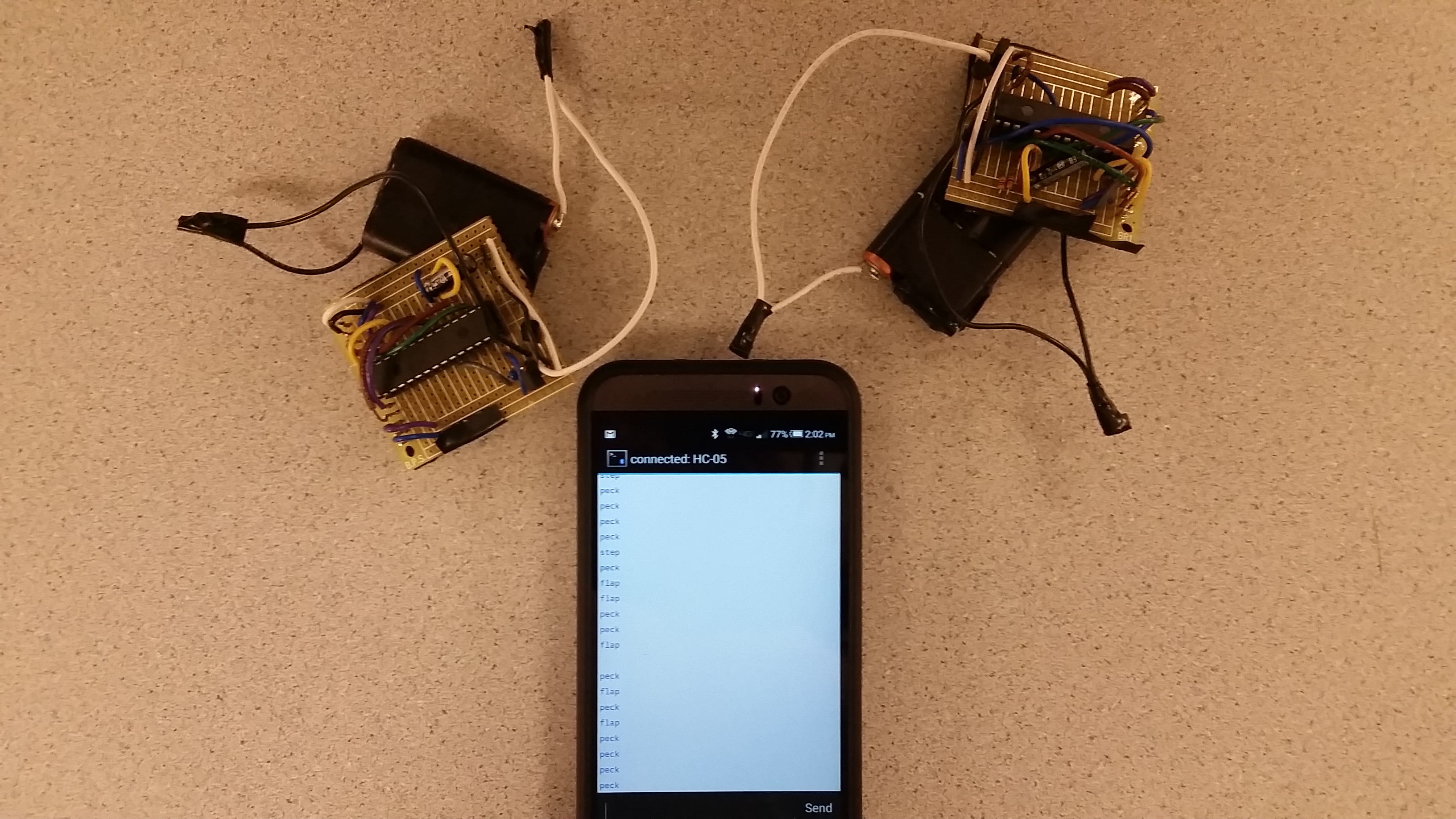
Figure 2: Working monitors connected to the uART interface via Bluetooth outputting both test data and real time tracking data.
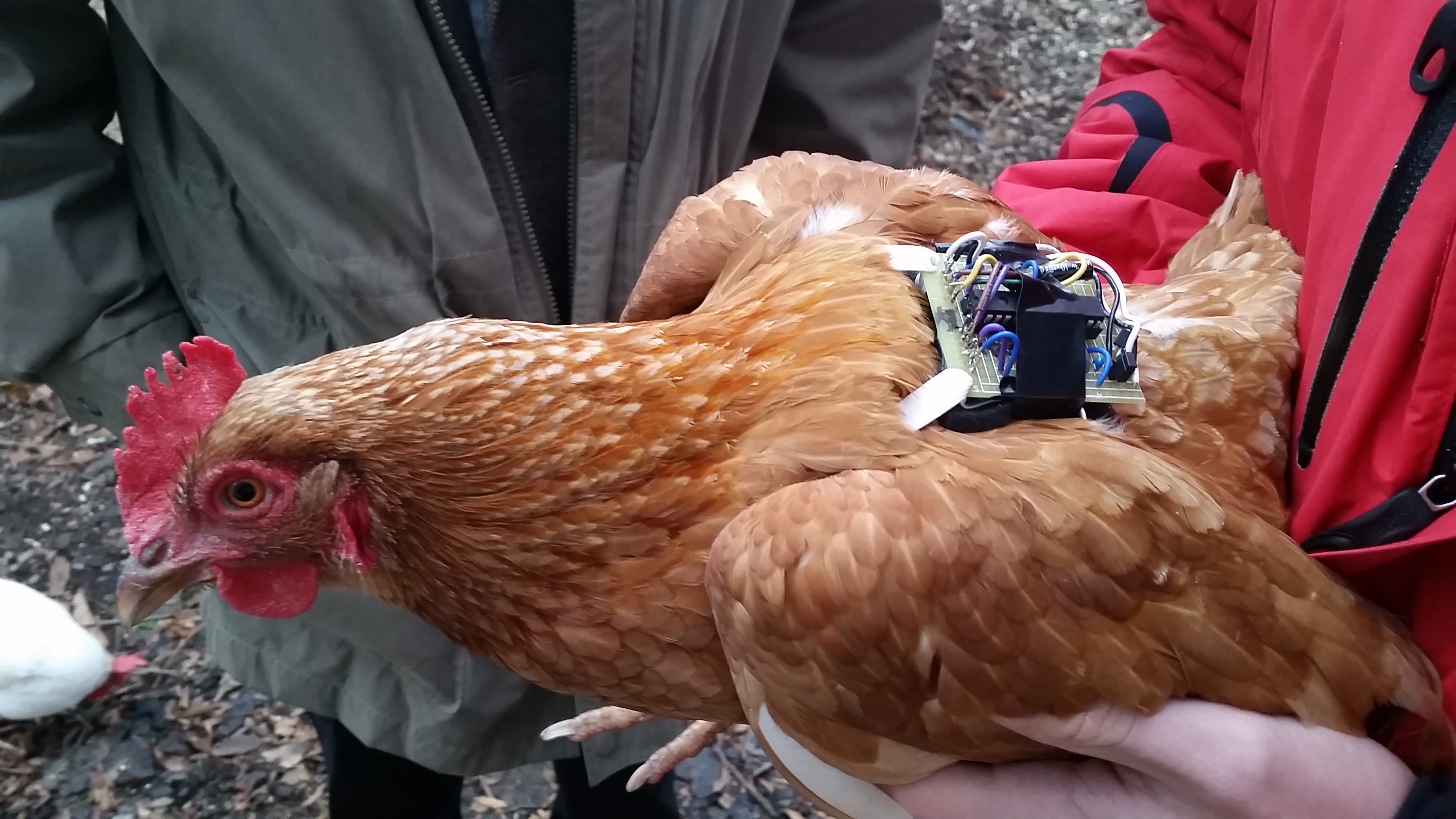
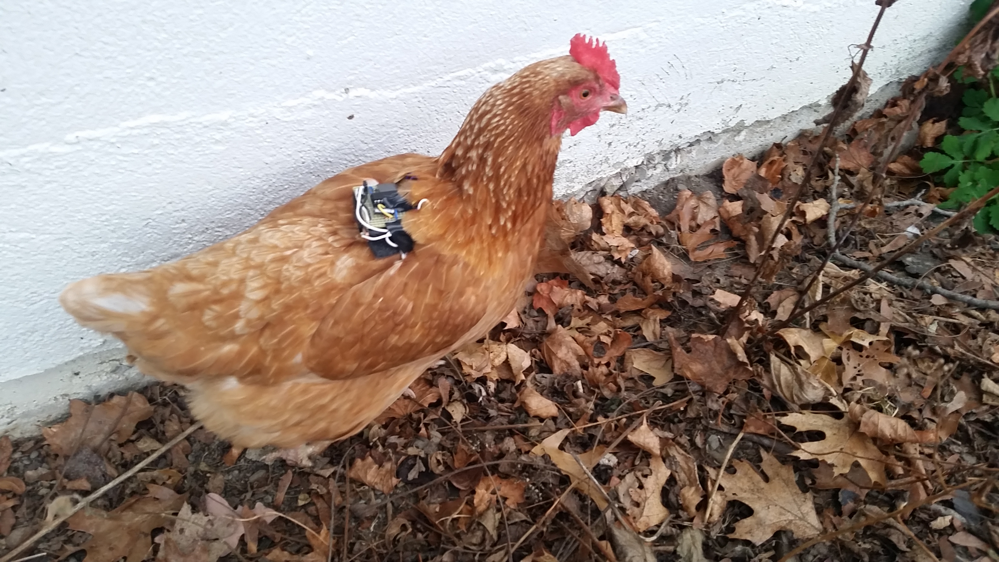
Figure 3: Prototype on chicken.
Video Demonstration of Working Project
High Level Design
Functionality
There will be 5 main functional tasks for this project:
1. Sensor hardware and software - There will be three total accelerometers used in this project, and one temperature sensor. One accelerometer will be placed on the head of the bird, another on the right wing, and the other on the right foot. This will allow for detection of walking, pecking, flapping, and other common behaviors of a bird. We expect that a major challenge will be calibrating these sensors to detect movement properly. To expedite this, the software parameters for detection will be easily adjustable (see 4). The temperature sensor will be placed beneath the feathers on the bird’s back.
2. Recording data - The specific movements that we capture using the sensors will be stored to memory on the microcontroller. From here this data will be extrapolated to count specific motions, determine frequency, or record any other information of interest.
3. Bluetooth radio hardware and software - This will consist of radio circuitry and microcontroller side software to interface with a computer radio. The data will then be packaged for sending over the radio link. This will also allow for configuration of the sensors and microcontroller from the computer program. Distance measurements between birds will be measured through communication of their Bluetooth modules.
4. Computer interface and data download - The computer interface will have the ability to adjust certain parameters on the microcontroller and thus calibrate the motion sensing. It will also have the ability to download the motion data saved on the microcontroller.
5. Battery and power - This will consist of a very small battery and power conditioning circuit to power the microcontroller for a useful amount of time.
User Interface
The user interface consists of two parts; the first part allows for configuration of the movement monitor, and the second part will allow for downloading of recorded movement data from a monitor. The download section of the user interface will receive the stored data from the movement monitor via Bluetooth and parse it into an easily exportable format for analysis and data manipulation with other programs such as .csv or Excel. Below shows the progression of the user interface that was built to monitor our program.
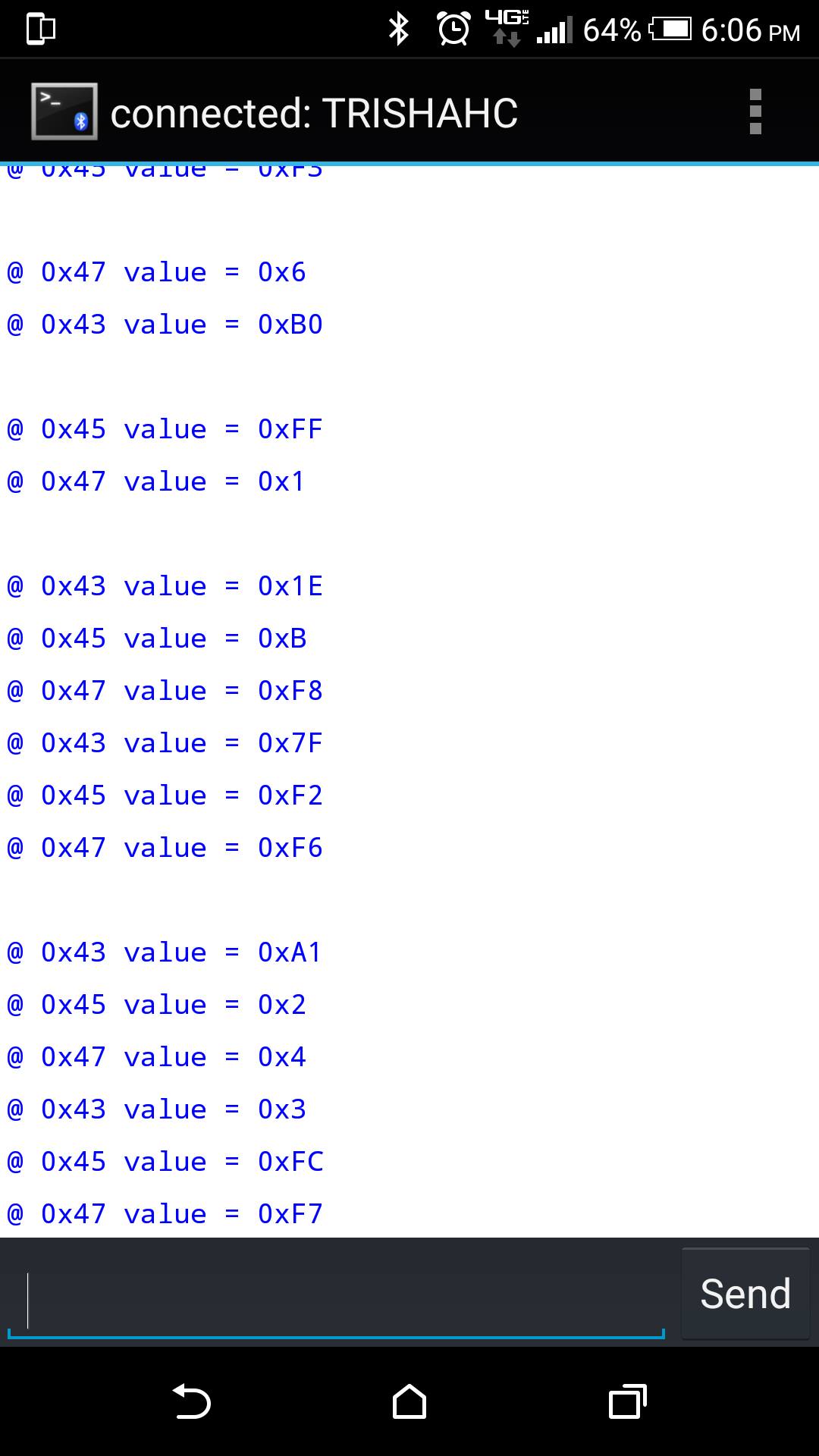
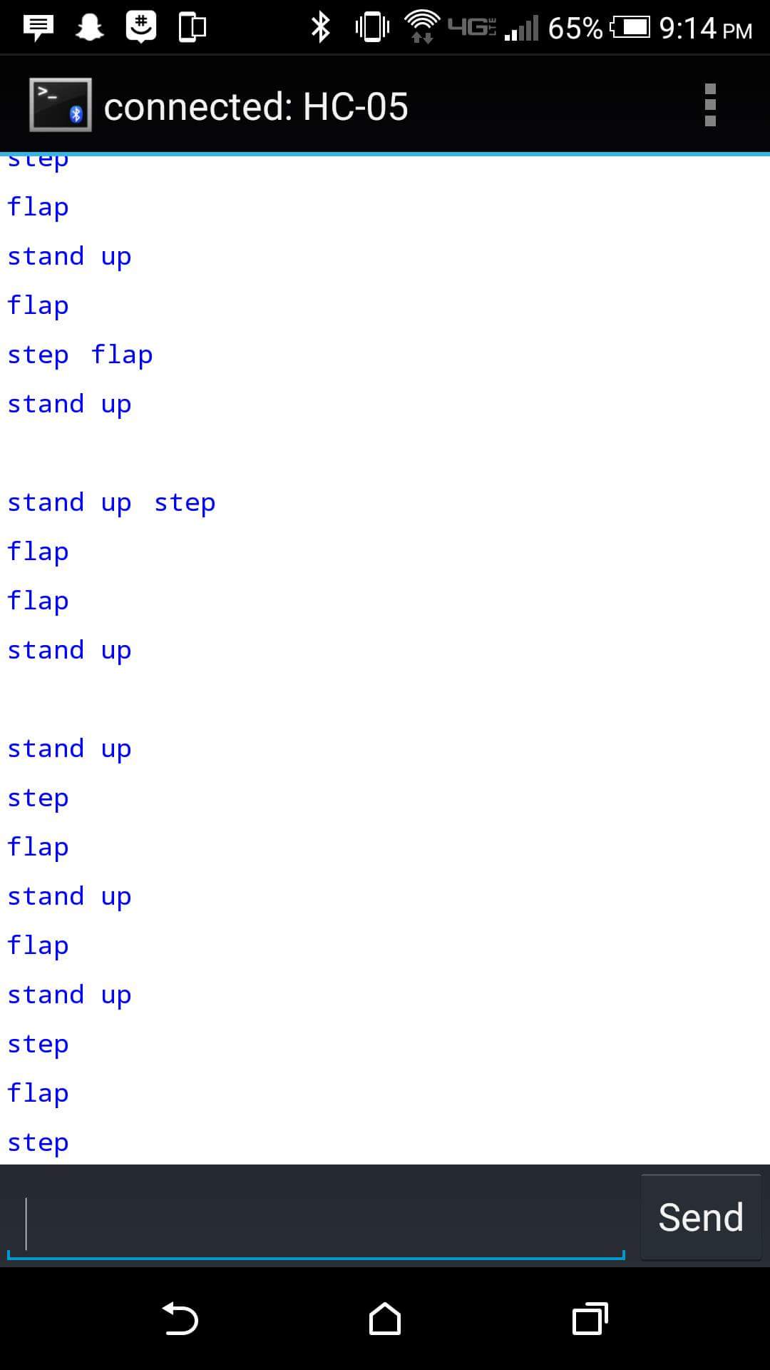
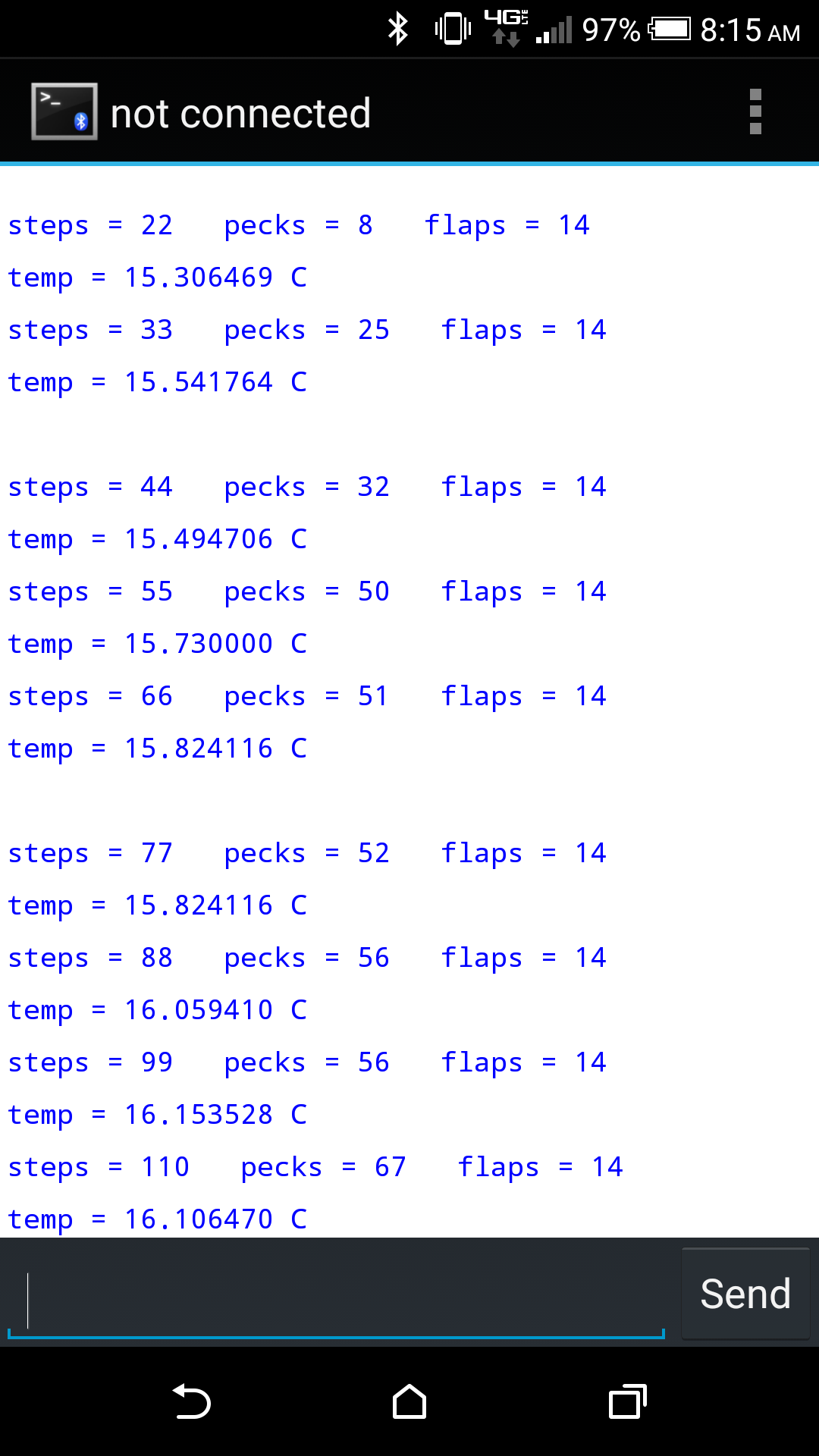
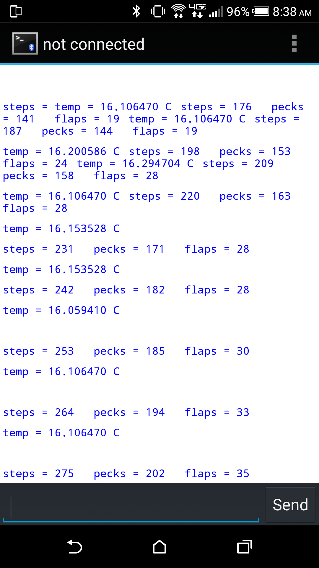
Figure 4: Interface results. First two figures are from test data, while second two figures are from real time data after being placed on a chicken.
Block Diagram
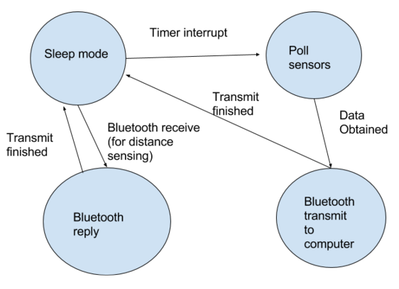
Figure 5: Block diagram of Bluetooth interacting with microcontroller
High Level Hardware Diagram
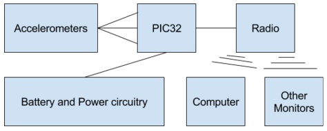
Figure 6: Diagram of all hardware components and their connections
Hardware and Software Tradeoffs
We chose to use polling to collect data from the IMU as opposed to an interrupt driven solution. We did this by using a slower poll rate than the IMU updates at so we don’t read two of the same values. A tradeoff of our polling implementation is that it uses more power than we would desire in a further iteration of this product. The MPU6050 has an interrupt pin that will trigger when a FIFO buffer saving accelerometer and gyroscope values becomes full. This could be used to keep the PIC32 off for long periods of time until the FIFO buffer is full, saving power.
A tradeoff that we were constantly playing with was power consumptions versus speed of any given operation. Even though above we chose to keep the PIC32 on all the time to poll the IMU, we made efforts to decrease the power consumption of the PIC32, the IMU, and the HC-05 Bluetooth module. This was accomplished by turning off unused measurement axis in the IMU, lowering the clock speed of the PIC32, as well as minimizing radio transmissions with the HC-05. Radio transmission via Bluetooth was the most power consuming task performed by the components, so we made sure the module transmitted data at the lowest user friendly frequency – we chose to show a cumulative total of steps, pecks, and flaps every 11 steps.
A final important tradeoff was the weight and size of the battery pack used versus the operational lifetime of the battery pack. Initially we planned on using CR2023 coin cell batteries to power the project, but because of the high current required when transmitting via the Bluetooth radio we chose to use the more powerful 3xAAA battery pack. Using the three batteries kept weight and size reasonably low for an initial prototype, but this would obviously need to change for any future iteration of the design.
Relevant Copyrights
Several elements of the relevant code that was used for the software portion of this project were created by Bruce Land, ECE 4760 Instructor and Syed Tahmid Mahbub, ECE 4760 teaching assistant as an example in the use of protothreads with the PIC32. Other code that was included was created in collaboration with Matt Filipek for the purpose of building a digital tachometer from previous lab work. We also used the modified PIC32 plib library and header file throughout the duration of the course to build our code (using various functions, methods, and code snippets).
In order to implement I2C we developed the code through various sources including Northwestern’s Neuroscience and Robotics Lab Webpage: PIC32MX: I2C Communication between PIC32s and Best-Microcontrollers-Projects: I2C Tutorial page. These pages were reviewed in order to find information on I2C functionality, data transfer sequence, acknowledgements, and minor code snippets. We also referred to the ECE 4760 peripheral library page for help with various I2C functions and syntax. We also looked at the ECE 4760 project “Wireless Pedometer” by Ellen Chuang and Julie Wang for their implementation of our HC-05 Bluetooth module. Links to these pages can be found under ‘References’.
Further discussion of relevant existing patents, copyrights, and trademarks is included in the Conclusions Section.
Hardware
Hardware Overview
The hardware was designed with three main considerations. The entire package has to be extremely durable and rugged to withstand the harsh environment of being on the back of a chicken and has to be low weight coupled with a small total size so the chicken is not encumbered. It was thus our goal to create a simple system, both small in size and rugged, which accomplishes the tasks of gathering the data and processing it. Appendix A: shows the electrical schematic used for the design, and a description of each hardware component and the minimum size layout used follows.
Package Layout and Description of Individual Components
The PIC32, IMU (MPU 6050), and HC-05 were all soldered to a PCB protoboard that also contained the necessary voltage regulator, capacitors, and resistors. The battery cell that we created was spliced into the circuit as well and positioned below the protoboard so the entire package was taller, but took up much less space. Finally we used a square of foam padding and elastic bands with Velcro connection points to prevent the motion monitor from falling off of the chicken and make sure that no extraneous shaking was recorded by the accelerometer.
The PIC32 was connected to both Vdd and ground along with properly sizedcapacitors where the datasheet specified they were required. Pin 26 was connected to the interrupt pin on the IMU so that the FIFO buffer improvement mentioned in the tradeoffs section might be implemented in a future iteration of the project. Pins 22 and 21 both connected to the HC-05 and served as receive and transmit for the serial UART communication. Pins 18 and 17 served as the I2C communication pins, with pin 17 serving as the master clock line and 18 serving as the data connection between the PIC32 and the IMU. Both of these lines also had pull up resistors with a value of 2kOhm, consistent with the values recommended in the I2C communication protocol.
The IMU or MPU 6050 was connected to ground and Vdd, with its additional I/Opins all connected to the PIC32 pins already specified above. The HC05 was also connected to Vdd and ground, with the I/O ports also connected to the PIC32 as described above. Note however that two pins were left unconnected, state and key, this is because the pins are used only in special operational modes of the HC05 modules (such as when adjusting communication baud rate), and do not need to be used or connected at any other time.
Power Supply
We also considered how we would power the wearable. Bruce mentioned using a voltage regulator (adding one would increase board area, and linear regulators will cause some power dissipation due to limited power converting efficiency). We decided that it would be best to use the voltage regulators and 3 AAA batteries that would directly supply 4.5V to the various components on the wearable. This battery can provide 250mAh, which should be able to power the sensor for a day or so (the big power consumer is the transceiver, which will draw ~15mA to transmit and receive, but it won’t be transmitting and receiving continuously).
Software
Software Overview
The software was designed with two main goals: clarity and customizability. Clarity – the code was kept as simple as possible, and in cases where tasks were more complex, abstraction and commentary are used to keep things understandable. Customizability was accomplished using a set of Dztuning variablesdzthat allow a programmer to quickly change the effective sensitivity of the accelerometers and gyroscopes to the movements of the chicken. Before any data manipulation code was written for the PIC32 we made sure that the communication interfaces were working. Thus we start with the I2C code that allowed us to read raw accelerometer and gyroscope values, continue to the Bluetooth and UART communication that allowed us to interface with the end user via a Bluetooth terminal on the phone. After this we discuss the code being executed by the PIC32that processes the raw data being collected and creates the outputs to send to the phone Bluetooth terminal.
uART and Bluetooth Communication
The serial UART code we used was primarily based off of our work from lab 4 which also used UART for communication. After UART is properly enabled in the configuration header of our program, we were able to use the function printf and a range of different formatting options to output whatever we needed in the final product. This simple system was also useful when debugging the program.
In order to log the data we have our HC-05 device send data to an Android app called 'Bluetooth Terminal' on our mobile devices. This app is essentially a terminal application purposed for Android devices. It's capabilities include sending (and saving) data between any Bluetooth device (such as the HC-05) and receiving data to file. It can enable any Android device to connect to any other remote Bluetooth device (both as a master or as a slave) that uses Serial Port Profiling. Details about Bluetooth setup, connection, and use can be found under 'Appendix D.'
I2C Communication
The I2C communication code utilizes the plib library for baseline functionality. After initializing the I2C interface, start, idle and stop commands can be issued to take control of the I2C bus. The master I2C device in this case is the PIC32 with the IMU being the slave device. We created a set of functions that write and read bits over the I2C bus. Both functions start by indicating the address of the slave and whether the master wants to read or write and waits for a response. Next the function outputs the specified register to read or write to and again waits for acknowledgement. Finally the corresponding function either reads the data from the I2C slave and saves it to a variable to be returned by the function or writes specified data to a register. The I2C register write function we wrote was used to configurethe power settings in our IMU by turning off unused gyroscope and accelerometer axis. The I2C register read function collected the raw data from the gyroscopes and accelerometers and saved it to variables so the information could be processed and interpreted by the rest of our code on the PIC32.
I2C Implementation
I2C is generally used to connect lower speed external or secondary components to processors and microcontrollers. In order to implement I2C we used I2C functions that were automatically built into the plib library. In order to do a data transfer sequence in I2c we follow the following:
- 1. Send the START bit (S).
- 2. Send the slave address (ADDR).
- 3. Send the Read(R)-1 / Write(W)-0 bit.
- 4. Wait for/Send an acknowledge bit (A).
- 5. Send/Receive the data byte (8 bits) (DATA).
- 6. Expect/Send acknowledge bit (A).
- 7. Send the STOP bit (P).
Side note: If you are trying to develop a I2C driver for this device using Microchip Plib functions like I2C2A,
then you are maybe trying to use the legacy versions of Plib I2C functions.
PIC32 Executed Code
The PIC32 first initialized I2C communications and the serial UART before entering a while loop that polled the IMU. The polling used the previously mentioned I2C register reading functions to read the accelerometer and gyroscope values and same them to variables. We also chose to implement and some data processing in the same loop, creating a running average of the past 10 accelerometer readings to smooth the data before further processing. The next step calculated the change between the previously calculated average and the new average. This was used in the final step where we detected 5 different states of the chicken: standing up, bent down, taking a step, flapping, or pecking. The standing up and bent down states are important for determining if the accelerometer is picking up a peck or a step (because the same axis accelerates in either case). Thus we use the determination that a chicken will peck only when it is bent down, and it steps when standing up. This allows us to use the data from the gyroscope to sort out between the two possible states. Finally, a flap was an acceleration in the upwards axis only. We used a threshold method, were if a certain acceleration or gyroscope value was reached (on average) and if a certain change between the last two averages was achieved, the motion sensor would increment the variable keeping track of the total steps/pecks/flaps. This system was relatively simple and also easily customizable, as a multiplier value was used to adjust the sensitivity for almost every parameter and every axis used. The programmer could easily change these as they are set at the very beginning of the program.
Testing and Results
Testing and Development Process
At every point in the development of our project we unit tested both hardware and software. We began getting I2C to work, which was where the bulk of the issues came in. We realized the main problem was that our acknowledgement code was incorrect thus our waveforms appear to be one bit off per cycle. After our struggles with I2C were solved we moved onto IMU setup. To incrementally verify the operation of the accelerometers, we initially looked at the raw digital output by taking the data from the accelerometer registers and processing them on the PIC32 to be printed to a UART debug terminal on the PC. Once we verified that digitalvalues corresponded to expected values (magnitude and direction), we began the process of implementing Bluetooth communication. Bluetooth communication was primarily based around serial UART, so some of the initial code that was used was taken from the Fall 2015 Lab 4 code that we had written earlier in the semester. Much of the Bluetooth setup and pairing information/explanation can be found in the 'Appendices' section. After successful implementation and verification of the Bluetooth link, we began experimenting with our device by placing the module on our own hands and emulating chicken movements. This was an easy hardware task to test as the results appeared directly onto our primary user interface and therefore were easily accessible.
Accuracy and Results
The accuracy of our project was incredibly high, if not suprisingly accurate. The step counts were verified while watching the chicken walk around during out test and comparing the manually acquired count to the count as recorded by our bluetooth module. This was repeated for all of the states that we kept track of, including pecking and flapping. This can be seen somewhat in the demo video, as the first ten steps are outputted in real time to the bluetooth terminal on the phone, allowing a user to verify accurate functionality of the monitor.
Animal Care and Use in Research and Education
Our project contained live animals via the Cornell poultry research facility. In order to gain access to the birds we needed to use for testing the device and our demonstration, we worked with Professor Debbie Cherney. Professor Cherney allow us gain expedited approval from the Cornell animal experiment review board. Being allowed to access the chickens will also mean a brief training period - which consists of reading some information and taking a course exam. These logistics provided us with a uniquely applied final project. Below are the certificates received after completing the necessary training.

Figure 7: Certificates from AALAS Learning Library
Radio Interference
Per our design, the Bluetooth modules used include frequency hopping, which means that each transceiver automatically scans al possible bandiwdths and only utilizes unused bandwidth to avoid RF interference with other modules.
Usability
We are hoping that the device might assist with detecting triggers for bird smothering events, keeping track of social health, and tracking stress. The general use case is meant for either chicken farmers or individuals raising poultry in their backyard. Our hope for this project is that it will act as a poultry management system designed to assist both farmers and individuals by enhancign their basic knowledge of the bird's movements and surroundings. We also hope for this project to help promote sustainable agriculture objectives.
Conclusions
Accomplishments and Further Extensions
Our goal for this project was to design a poultry movement monitor. We have met these expectations and this project was completed in a successful manner. Included in our final product, we were able to fully and functionally build an un-intrusive movement tracking system intended to be worn by a domesticated bird. The system is capable of detecting and recording animal movements and body temperature and wirelessly reporting the collected data toa compute via Bluetooth. Bluetooth modules on different birds were able to interact in order to detect distances between them as well. Though we did not reach the level of accuracy and precision that we wanted, we are pleased with what we have accomplished. There are several things we would do differently given more time.
Some improvements that could have been made to this project would have been to invest in a smaller but more powerful Bluetooh module since our current one (HC-05) had a limited range of 30 feet hence as you can tell from the video, we had to follow the chicken to maintian range. We would also have liked to use smaller batteries since we needed to include a voltage regulator because our three AAA batteries directly supplied 4.5V to the various components on the wearable and we only required 3.3V.
Some extensions that could be explored include implementing proximity sensors so that we would have been able to test our modules on each bird in relation and comparison to other birds within proximity. The purpose of this would be to obtain info on surrounding birds and help keep each bird regulated amongst one another. One other extension that could have greatly improved our project would have been to add a small alarm that would alert surrounding birds and scare them off in case a bird was being smothered it would also alert farmers of their movements and interactions were unconventional.
Overall, however, the outcome of the lab was a success.
Conforming to Standards
The standard we will be using for communication between the accelerometers, radio and the microcontroller will be I2C. The radio circuit will be using Bluetooth (via the Bluetooth Special Interest Group) and can easily be configured using a Bluetooth equipped computer. We had to purchase a Bluetooth radio IC that was FCC compliant.
The HC-05 Bluetooth module is a Class II Bluetooth device that operates in the 2.4-2.485 GHz Industrial, Scientific, and Medical frequency band. As a licensed Bluetooth device, this module complies to Part 18 of FCC standard. It also employs a UART link for its host controller interface, the details of which are entailed in Appendix D: Bluetooth and HC-05 Bluetooth Configuration and Usage. Communication in AT mode (configuration mode of the HC-05) was conducted at 38400 baud. Functional communication of data was conducted at 9600 baud. There is no packet structure standard to follow, so we implemented our own. The Bluetooth protocol is described in much greater detail in Appendix D: Bluetooth and HC-05 Bluetooth Configuration and Usage.
Intellectual Property Considerations
As discussed in the ‘Relevant Copyrights’ section of this page, our code is built upon Northwestern’s Neuroscience and Robotics Lab Webpage: PIC32MX: I2C Communication between PIC32s, Best-Microcontrollers-Projects: I2C Tutorial page, and instructional code provided by Bruce Land and Syed Tahmid Mahbub.
The plib library source and header files are taken from the Microchip website.
Our uART code for communication with the Bluetooth modules was edited from general code developed in collaboration with Matt FIlipek from eCE 4760 course material.
Our HC-05 Bluetooth communication code was partially inspired by ECE 4760 project: “Wireless Pedometer” by Ellen Chuang and Julie Wang, however, the code itself was written from scratch to tailor to our own design.
The rest of the code is our own.
Ethical Considerations
Throughout the course of this project, we adhered to the IEEE Code of Ethics. We made a great effort to be “honest and realistic in stating claims or estimates based on available data” by including all unedited collected data. Much of our success can be attributed to the staff and peers of ECE 4760 who were readily available to bounce ideas off of and to provide insight into our design and idea.
During the actual design portion of this project we were always able to “maintain and improve our technical competence and to undertake technological tasks for others only if qualified by training or experience, or after full disclosure of pertinent limitations.” We gained a lot of experience both inside and outside of lab while building the physical prototypes and programming the necessary software.
We continuously followed the ethical code of conduct and never failed to provide accurate and unbiased accounts of all data and information provided in this project and webpage.
Societal Impact
The movement monitor will be built with an emphasis on the safety of the bird wearing the device. Low power electronics are to be used in all cases, and special attention will be paid to ensuring that the device is enclosed, that the battery is protected from short circuits and overheating, and that the physical device and wires do not obstruct the birds movement. Use of the device should be monitored at all times to ensure that birds do not attempt to peck at the device. The bird wearing the device should be separated from other birds to prevent tangling of wires or anxiety to other birds. Human usability will be maximized via the radio interface and computer program. The program will assist with any configuration changes and all data transfers. To the best of our team’s knowledge this project will not interfere with any existing intellectual property claims. In the future, the group or a member of the group may choose to expand upon this project with written permission from the other group members. For the RF radio we will be using Bluetooth technology. Bluetooth transceivers available on the market will necessarily be FCC compliant before they can be sold publicly.
Legal Considerations
After reasonable discussion, we do not believe that there exist any legal considerations for our project and design. All materials used in building our project were rented through the university or purchased through a manufacturer and were properly cited. The communication and radio involved the use of a Bluetooth module which was strictly regulated by FCC standards to prevent excessive radio interference, thus, our design does not create EMF interference. Our group is interested in pursuing a patent for our project, hence, we will adhere to the legal process of filing a patent application:
- Keeping careful records of our design
- Determining whether our design qualifies for patent protection
- Assessing the design’s commercial potential
- Doing a thorough patent search
- Preparing and filing a patent with the USPTO
Appendices
Appendix A: Schematic
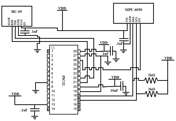
Figure 8: Schematic of all hardware used in design
Appendix B: Parts List and Costs
| Item | Part Number | Quantity | Cost Per Unit | Total Cost |
|---|---|---|---|---|
| Breadboard - Rental | NA | 1 | 6$ | 6$ |
| Small Solder Board | NA | 4 | 1$ | 4$ |
| PIC32 | PIC32MX250F128B | 2 | 2$ | 4$ |
| Bluetooth Transceiver | HC-05 JBTek | 2 | 5$ | 10$ |
| 6 DOF Gyro and Accelerometer IMU | MPU-6050 RB-DFR-264 | 2 | 2$ | 4$ |
| Batteries | AAA | 6 | 5$ | 10$ |
| Capacitors | 10uF, .1uF | 6 | 0$ | 0$ |
| Dip Sockets | NA | 2 | 0$ | 0$ |
| Miscellaneous Wires & Resistors | NA | NA | 0$ | 0$ |
| Total | 39$ |
Appendix C: Division of Labor
Every portion of this project was worked on by both team members, whether through brainstorming, coding, or debugging. Due to the enormity of our task though, there were certain areas that one team member had greater responsibility for. These are detailed below.
Trisha Dey
- Bluetooth Setup
- Most hardware
- Webpage creation
Both
- Debugging
- Testing
Kevin Kreher
- Bluetooth Pairing/Setup
- Most software
- Webpage additions
- Chicken procurement logistics
Appendix D: Bluetooth and HC-05 Bluetooth Configuration and Usage
Bluetooth Protocol
Bluetooth is a short-ranged RF, wireless connectivity standard. It has a master-slave structure where one master is connected and can communicate with up to 7 slaves. Bluetooth operates at frequencies between 2402 and 2480 MHz, or 2400 and 2483.5 MHz including guard bands 2 MHz wide at the bottom end and 3.5 MHz wide at the top. These devices do not interfere with each other because Bluetooth uses a(AFH), which improves resistance to radio frequency interference by avoiding the use of crowded frequencies in the hopping sequence.
This Appendix explains how the HC-05 module was utilized in our project. This module consists of the HC-05 chip which includes a Bluetooth serial port profile (data sheet can be found in 'References' section). The HC-05 handles the implementation of the Bluetooth stack, contains the necessary hardware for a radio and link controller, and contains the firmware for the link manager.
HC-05 Bluetooth Technical Specifications
Protocol: Bluetooth Specification v2.0+EDR
Frequency: 2.4 GHz ISM Band
Modulation: Gaussian FSK
Emission Power: Class 2, < 4dBm
Sensitivity: < -84dBm at 0.1% BER
Speed: Asynchronous, 2.1Mbps(Max) / 160 kbps; Synchronous, 1Mbps/1Mbps
Security: Authentication and Encryption
Default Passkey: 1234
Profiles: Bluetooth Serial Port (SPP)
Power Supply: +3.3V
Operating Temperature: -20 - +75 Celcius
Storage Temperature: -40 - +85 Celcius
Nominal Current: Pairing, 30-40mA; Communication, 8mA
Configuring the HC-05 board
- Be sure to power off the HC-05
- The following port must be conected on the HC-05 chip:
- TXD to the receive of the PIC32 (i.e. Pin 22 RB11)
- RXD to the transmit of the PIC32 (i.e. Pin 21 RB10)
- 5V to power (3.6 - 6V)
- GND to gnd
- KEY not assigned
- STATE not assigned
- Connect other end of serial cord to the USB port of your machine
- Open up a puTTy terminal, or serial terminal program of your choice, with the following parameters:
- Serial Line: Find using Device Manager
- BAUD: 38400 bps, 8 bits, 1 stop bit
- Parity: None
- Flow Control: None
- Implicit CR in every LF: Yes
- Implicit LF in every CR: Yes
- Local Echo: Yes
- Power on the HC-05. It will come up in AT command mode. Verify that you have connected everything properly and configured puTTy correctly by issuing the command: AT<enter>
- The HC-05 should respond with a number of “OK”’s. If you get a response that says ERROR=0 that means you formatted the AT command error incorrectly. Double check the puTTy configurations and the baud rate. IF this doesnt work, try cycling th power.
- Specifiy your master and slave devices
- Set as Master:Command: AT+ROLE=1<enter>
- Set as Slave: Command: AT+ROLE=0<enter>
- Verify that you have correctly set each by issuing the query:
- AT+ROLE?<enter>
- 0 -- slave role
- 1 -- master role
- 2 -- slave-loop role (repeats data received back to the master)
- Power off the device. Remove the connection from Power to KEY, change the BAUD to 9600, and power on both of the devices.
- The master sets up the pairing. Both will power up in an unpaired state where the master and slave blink quickly. The units will automatically pair. Once paired, the state LED, if connected to the HC-05 chip, will begin a cycle of flashing twice then turning off for a period of time.
- Congrats! You just set up Bluetooth pairing. For more information check the datasheets linked in the 'References' section.
Appendix E: Source Code
The source code is attached as a file with the configuration header, our custom cornell protothreads header, and the main execution program c file.
Acknowledgements
We would like to thank Bruce Land and the Fall 2015 TA's for all of their help throughout the semester. Whether it was debugging, brainstorming, or just discussing project ideas, the instructor and TA's were invaluable resources. In particular we'd like to thank Bruce for always being available to and ready to help. We would also like to thank Ellen Chuang and Julie Wang for allowing us to utilize their group's web site layout.
