Smart Watch
Matthew Filipek (mjf332@cornell.edu)
Introduction
High Level Design
Hardware Design
Software Design
Results
Conclusion
Appendix
Introduction
Wearables are becoming increasingly more prevalent in today’s markets; however cost continues to limit the demand for such devices. My project aimed at producing a smartwatch with comparable functionalities to those available today, while running a total cost of less than $100. The watch is outfitted with a 1.7 inch touch screen, SD card, Bluetooth module, and various apps.
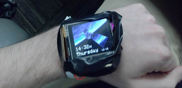
Figure 1, finished watch
High Level Design
Rationale:
One of the main inspirations for this project was Jared Sanson’s implementation of a DIY smartwatch (REF 0). With several design iterations, he was able to produce a watch in a very small package that can communicate with a PC via USB HID, features an OLED display, and has support for an accelerometer. As my project was to be completed in the span of a mere month, several of the components I got were purchased for their ease of use rather than their compactness. As a result of this, and the fact that I did not have time for any PCB revisions, I started this project expecting my watch to be a bit larger than his. I also wanted a touchscreen interface, and the smallest TFT touchscreen I could find was 1.8 inches, which already makes my watch fairly large. Another factor that enlarged the watch volume was battery life. I wanted a watch that could last at least 9 hours in idle mode, which meant that a fairly large battery was required. In short, because of time constraints, I knew my watch could not be quite as polished as watches you would see on the market, or the DIY watches on hackaday, but I wanted to have a product that could be comfortably worn on the wrist and used without too much difficulty.
User interface
The watch currently has 3 apps: a settings app where the user can set screen brightness, change the time and date, and change the theme of the user interface; a game app, where the user controls a small paddle with the touch screen and attempts to deflect balls into goals; and a paint app, where the user touches to draw one of 8 selectable colors to the screen. The watch also has Bluetooth functionality, where it relays the time and date to a paired device upon receiving any character from said device.
An elastic strap is used to tether the watch to the user’s wrist. In order to extend battery life, the screen is set to turn off after 10 seconds of inactivity on the home screen. The watch wakes when a button on the side is pressed, and the sleep timeout is disabled if the user decides to proceed past the home screen. A resistive touchscreen on the TFT is used to navigate through menus and use the apps. Date and time are displayed on the home screen. Touching the screen anywhere will bring the user from the home screen to a menu with all of the app icons. The user may then select an app by pressing on it. The apps also make use of the touch screen for user input. The 600mAh LIPO battery can be charged with an on-board charger. There is a mini-USB port on the side of the watch for powering the charger.
Logical Structure:
The software was essentially a giant state machine, a simplified version of which is shown below. Bruce Land’s adaptation of Adam Dunkels’ protothreads library was used (REF 1) to manage the various processes. For a given state, a specific selection of protothreads were scheduled, when a state transition occurs, some protothreads simply are passed over in scheduling, while others are included. The protothread structure limited software overhead for scheduling, but requires that all threads are essentially running at once, with memory allocated for all of them at any given time. For the purposes of this project, protothreads was more than sufficient, however if many more apps were to be added, it would be necessary to use a different scheme.
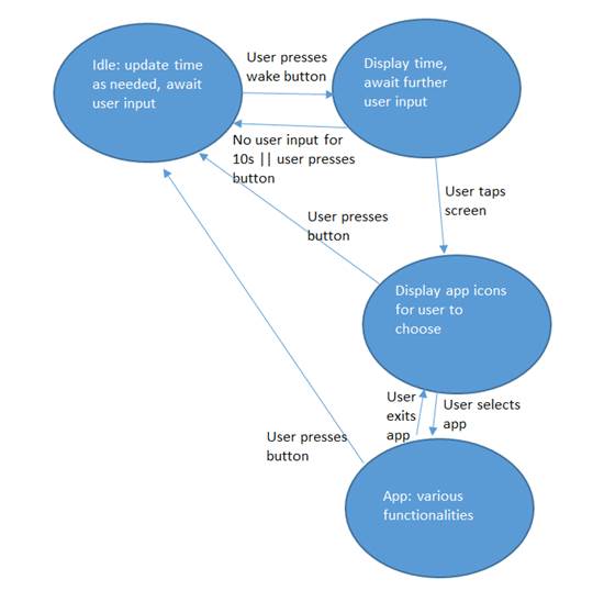
Figure 2, simplified FSM
Standards:
Bluetooth was used to communicate with a paired cell phone. The Bluetooth module, the HC-05, complies with the Bluetooth 2.0 standards. 20MHz SPI was used for communication between the microcontroller, the SD card, and the TFT screen. The TFT screen used a 9-bit SPI command set, which is described in more detail in the “hardware and software tradeoffs” section. Communication between the microcontroller and the Bluetooth module was done via UART, running at 115200 baud. The SD card was formatted with FAT32, and all images stored in the SD card were bitmaps (BMPs).
Hardware and Software Tradeoffs:
In order to save pins on the microcontroller, a 3-bit SPI protocol was used to interface with the TFT screen rather than a 4-bit SPI protocol. This means that instead of having a dedicated wire for the D/C bit (to specify whether the next byte is a command or data), a single bit is sent over the MOSI line before each byte transfer. The PIC32 only has support for 8-bit and 16-bit transactions, so a single bit had to be bit-banged, and then an 8-bit SPI transaction could occur as normal. The result of this extra bit is that all transactions to the screen take extra time and have extra CPU overhead. For most situations, this was not a problem since most of the processes on the watch were not very CPU intensive, however it did reduce the framerate of the game app. If it were not for the game app, the CPU system clock would be decreased to a lower frequency in order to save power, however the game would be nearly unplayable if its framerate were to drop much more.
- Program/hardware design:
- program details. Could someone else build this based on what you have written?
- hardware details. Could someone else build this based on what you have written?
- Be sure to specifically reference any design or code you used from someone else.
- Things you tried which did not work
Hardware Design
Circuit Board:
In order to miniaturize the device as much as possible, a custom
PCB was designed using DipTrace, and manufactured by OshPark (REF 2). Figure 1
below shows a picture of the unpopulated PCB, while figure 3 shows the layout
on DipTrace, which has been annotated to show the placements of components. 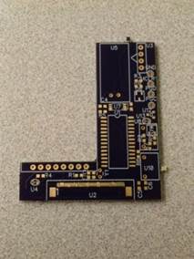
Figure 3, unpopulated PCB
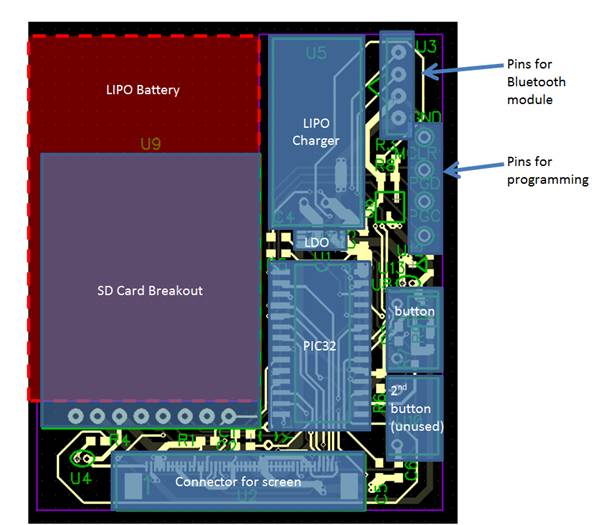
Figure 4, PCB layout with component footprints labeled.
It is important to note that the SD card rested on top of the battery, and that the bluetooth module was connected via wires to the pins, then placed on top of the PIC32, LDO, and LIPO charger. The TFT had a flat flexible cable that mated with the flat flexible connector on the bottom of the board. The screen was mounted behind the board, facing away from it. The PCB is L-shaped to allow for the LIPO battery to rest in the cutout.
Battery and LDO:
As was stated previously, one of the target specifications was to have a battery life greater than 9 hours. In order to select a battery of sufficiently large capacity, the average current draw of the watch in idle mode had to be calculated. The Bluetooth module will draw about 25mA (REF3) , the screen (when the backlight is off) draws 15mA(REF 4) , the SD card can draw large amounts of current on reads and writes, however will draw a negligible amount of current when the watch is idle, the microcontroller will draw about 20mA when running at 40MHz (REF5). With these considerations in mind a chose a 600mAh battery; this means that the watch will last for 10 hours in idle mode. To extend battery life even further, sleep mode could be implemented for the microcontroller (reducing its current draw to 20uA), and the Bluetooth module can be put into idle mode (reducing its current draw to 5mA). Because the LIPO battery can have a voltage output of up to 4.2V when fully charged, a linear regulator was used to step the voltage down to 3.0V. Capacitors were placed at the input and output of the LDO, as well as at the V+ pin on the microcontroller in order to ensure that the voltage supply remains stable throughout device operation.
Touchscreen:
The screen was a 128x160 TFT screen (DM-TFT18-310), which used a 9-bit SPI protocol, in which the first bit sent is a D/C bit, and then a byte transaction occurs. I used the TFT libraries from the course website, but modified them to accommodate for the 9-bit SPI, and for the different register addresses in the display controller. To send 9 bits, the SPI module was turned off, the data line was manually controlled, a clock pulse was manually send, and then the SPI module was turned on again and the tx buffer filled with a byte transmission. The touchscreen was composed of 2 resistive sheets laid on top of the TFT, which would electrically contact one another when the top sheet was depressed (REF 6). A voltage would be applied across one sheet, and the voltage at the other sheet is read by the microcontroller’s ADC. When the two sheets touch, a voltage divider is formed, and the voltage read in ADC will depend on how close the touch was to the pad at which a positive voltage was applied. The roles of the two sheets are then swapped, with the voltage being applied across the other sheet, and the result of that voltage division read.
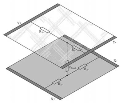
Figure 5: Resistive Touch screen
Whenever the roles of the resistive strips were switched, a delay of 5ms was applied before an ADC reading was made in order to allow the input to stabilize. The average human reaction time is 0.25 seconds, so the 10ms delay between readings (2 ADC readings must be taken before the touch coordinates are obtained, one for each sheet) is a negligible amount of time.
The image on the TFT screen is not visible unless the backlight is turned on. Since the backlight requires up to 80mA of nominal current, and the maximum amount of current that a pin on the microcontroller can source is 15mA, a BJT had to be used to amplify this current. Below is a diagram of the circuit used to power the backlight. R5 is used as a current limiting resistor for the microcontroller input, and was set at 220 Ohms. R6 is a pull-down resistor, which keeps the base voltage at 0V when the microcontroller input is low and prevents noise from turning on the screen. The resistance of R6 was set at 2200 Ohms. The input into the base of the BJT was a PWM signal, the duty cycle of which could be set by the user to select a screen brightness. The output compare module was used to generate the PWM.
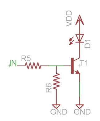
Figure 6: Backlight power circuit
Button
The button was simply connected between vdd and a digital input on the microcontroller. The digital input was pulled low with a pull-down resistor. A button press would pull the pin high. The button was polled every 20ms, and the input had to be high for two consecutive input reads for a button press to register in order to debounce the signal. Similar debouncing was done for button releases as well, where two consecutive inputs had to be low for the button to register as released.
Oscillator
The internal RC oscillator in the PIC microcontroller can have inaccuracies of up to 0.9%, which would result in a drift of about 13 minutes per day. Consequently, a 32kHz MEMS oscillator was used, which can provide accuracy to within 100ppm(REF 7). The output of the oscillator was inputted into the secondary oscillator input on the microcontroller, and was used to run the RTCC module. The RTCC module (real time clock and calendar) records the time of day and date without any CPU overhead. Because the MEMS oscillator was a surface mount component, it was often difficult to test with, so an op-amp oscillator circuit was made. Below is the schematic of the op-amp oscillator.
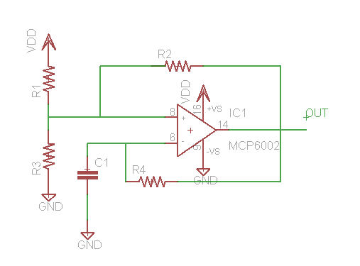
Figure 7: op-amp oscillator circuit
An MCP6002 op-amp was used. R1, R3, and R2 were set to be 1kΩ, while R4 was 690Ω, and C1 was 20nF. There circuit was calibrated by setting all resistors equal to 1kΩ, then adjusting R4 to achieve the desired frequency. R4 controls the frequency of oscillation because it determines how fast C1 can charge. As the resistance of R4 is decreased, C1 charges faster, and the circuit oscillates at a higher frequency. This circuit was first attempted with an LM358, however the outputted waveform was a triangle wave of fairly low amplitude due to the device’s low slew rate. With the MCP6002, a pk-pk amplitude of 2.72V and a frequency of 32.79kHz (accurate to within 0.07%) was achieved. With the MCP6002, slew rate effects can still be observed on the output waveform, and the non-idealities of this clock signal resulted in inaccuracies in the RTCC’s timekeeping.
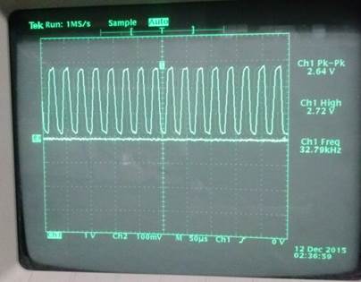
Figure 8: op-amp oscillator waveform
SD Card:
The SD card breakout board was soldered onto the custom PCB, and SPI connections as well as power and ground were made. As was mentioned earlier, the SD card was formatted with FAT32. To fetch data from the SD card, I used libraries written by Syed Tahmid Mahbub (REF 8). I also used Tahmid’s code for displaying bmp images to the screen, which transferred blocks of data from the SD card to the microcontroller, then wrote them to the TFT screen. One interesting quirk in the software was that the SPI status bits and configuration bits had to be modified before an SD card transaction if there had been activity on the bus involving the TFT screen. The fact that the SPI module is turned off and on every time data is sent to the screen (for the bit-banged 9-bit spi) is possibly to blame for the incorrect configuration and status bits.
Laser and vibration motor:
The PCB had slots for a laser diode and a vibration motor. The laser diode would be turned on with a second button on the watch, which would connect directly between the laser and vdd, with no microcontroller involvement. Unfortunately the laser diode that was ordered did not work as expected. A vibration motor was also ordered, and connected in a similar fashion as the backlight of the TFT screen (see above diagram), except there was an additional flyback diode placed between the terminals of the motor to protect against back EMF. The vibration motor failed to turn on when current was fed into the BJT, possible due to insufficient current gain on the BJT.
Bluetooth:
The HC05 communicates with the microcontroller via UART. As such, the UART libraries on the course website were used. The functions in this library make use of the DMA (direct memory access) to transfer the data with minimal CPU overhead. So far, all the watch does when it receives a character over bluetooth is sent out the date and time it has in the RTCC registers. Below is a picture of the smartwatch’s output to a bluetooth terminal on a cell phone.
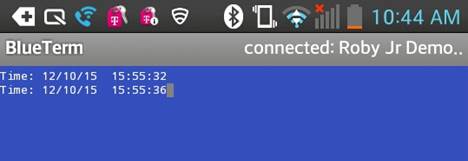
Figure 9: bluetooth output
Software Design
Below is an FSM of the code. For a given state, only certain protothreads are scheduled. The scheduled protothreads of each state are shown, and each protothread’s functionality will be explained in this section.
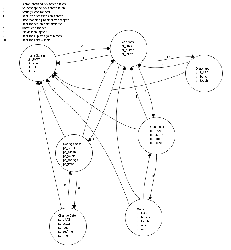
Figure 10: Full FSM
Whenever a state transition occurred, a function, drawstateX() (the X being the number of the state being transitioned to), would be called. In the special case of the game state, any transitions to another state from the game state would turn off timer 4 (used exclusively for the game) and reset all of the game variables so that it could be played again at any time.
States:
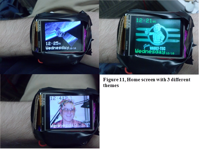
Home Screen:
This screen displays the date and time along with one of three settable backgrounds. To proceed to the app menu, the user simply has to tap anywhere on the screen. In order to save battery life, the screen turns off if the watch remains in the home screen for more than ten seconds. This timeout feature is disabled in all subsequent states.
 |
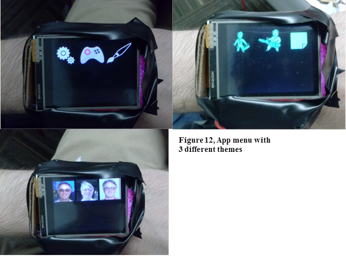
App Menu:
In this state, app icons are displayed. To navigate to one of the apps, the user must tap one of the app icons. This screen also has three different formats depending on the theme.
 |
Settings Menu:
In this menu, the user can set the brightness via the slider on the top of the screen, set the theme, or the time of day. Tapping on the time will bring up a keypad, which lets the user edit the time. The “<” icon can be pressed to go back to the app menu.
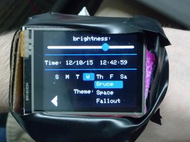
Figure 13, Settings menu
Change Date:
The data and time can be modified in this state. The user inputs values into the keypad to change the highlighted parameters. The highlighted box moves from left to right as the user updates the settings. The user modifies the month first, then day, year, hour, minute, and then second. Unfortunately the order in which these parameters are modified cannot be changed, but if the user modifies some of the earlier values in the sequence and does not want to change the later ones, he/she can press the check mark icon, and the old values for the later parameters will remain unchanged. If the user makes a mistake and sets a value incorrectly, he/she can move the cursor to the left by pressing the “<” button. Note: the brightness value cannot be modified in this menu, the slider was a part of the last state, and was left in for the visual effect of the keyboard being overlaid on top of the last screen instead of looking like the watch transitioned to a completely different state.
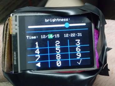
Figure 14, setting time and date with touch keypad.
Game Start:
In this state, the user sets the number of balls to be animated in the game by moving the slider back and forth. The “<” icon in the corner can be pressed to go back to the app menu, while the “continue” button starts the game.
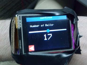
Figure 15: start menu for game
Game:
The game rules are as follows: the pink paddle at the bottom of the screen can be moved left and right by pressing on the screen. Balls shoot from the top, and if they reach the bottom, points are deducted. If a ball reaches one of the red collectors on the side, points are awarded. The green balls are worth 1 point, the red ball is worth 10 points, and the blue ball modifies the size of the paddle. Letting the blue ball fall will decrease the size of the paddle by 15 pixels, while scoring it in a collector will increase the size if the paddle by 15 pixels. The game ends if 30 seconds have elapsed, or if the paddle size drops below 0. The score, high score, framerate, and time remaining are displayed on the top of the screen. The high score is saved even when the user exits the game and returns. When the game ends, a game over screen appears (still the same state), and asks the user if he/she would like to play again. If the user selects to play again, he/she is brought back to the game start state, where he/she selects the numbers of balls again. The user also has the option at any time to go back to the app menu by pressing on the “<” icon in the upper left corner.
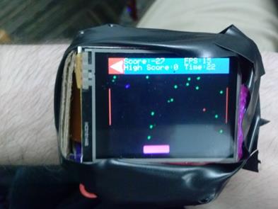
Figure 16: gameplay
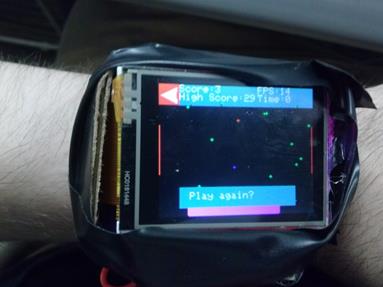
Figure 17: game over screen
Draw App:
In this state, the user can select a color to draw with from the list on the bottom of the screen by simply tapping one of the colored boxes. The box in the upper right corner shows which color is currently selected. The user can draw anywhere in the black space. The “<” icon will bring the user back to the app menu.
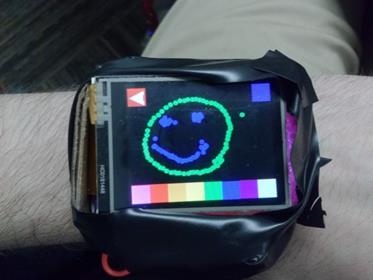
Figure 18: paint tool
Protothreads:
Protothread_timer:
This protothread fetches data from the RTCC module and displays it to the screen. It is only active in states where the time is actively displayed on the screen, namely the “home screen” and “settings app” states.
Protothread_UART
This protothread is active in all states, and manages the bluetooth communication. Whenever it receives a character from the bluetooth module, it sends the date and time to the module to be sent over bluetooth. This protothread is a slightly modified version of what was used in lab 4.
Protothread_button
This protothread is also active in all states, and polls the button. It performs debouncing operations, as explained in the hardware section. When the screen is off, pressing the button will turn the screen on. When the screen is on, pressing the button will return the watch to the home screen and turn the screen off.
Protothread_touch
This protothread is active in all states, and monitors for touches on the resistive touchscreen in the same manner as described in the hardware section. Many of the state transition logic is also present in this thread.
Protothread_settings
This protothread allows the user to change the theme, the screen brightness, and the day of the week. It does all of the interactive animations, such as a slider for brightness setting.
Protothread_setTime
In this protothread, the time is set according to keypad presses. The RTCC module is turned off in this thread so that the new values can be loaded in as they come.
Protothread_setBalls
This protothread animates a slider that the user can manipulate to set the number of balls that will be animated in the game
Protothread_anim
This protothread is very similar to the one used in lab 3. It animates the balls as they fly across the screen, and simulates collisions with billiard-ball dynamics. It also keeps track of the score of the game.
Protothread_rate
This is a framerate-limiting protothread for the game. Because the framerate will vary depending on how many balls have to be animated, this thread ensures the same user experience regardless of ball count by setting the framerate at 30 fps. This thread proved to be unnecessary, since the framerate was always below 30fps. The low frame rate can be ascribed to low SPI write speeds for the TFT screen due to the need to bit-bang the extra bit in each nine bit transaction.
Results
The watch was able to accurately keep time with the 32kHz MEMS oscillator. To test its accuracy, the watch was placed alongside an android phone running a stopwatch and left to run for 10 minutes. There were no noticeable deviations in that time. When running it off of the op-amp oscillator, the watch was fast by about half a second every minute, putting it at about 0.83% error. As was shown above, the op-amp oscillator was accurate to within 0.07%, so the deviation is probably due to the fact that the clock pulse produced by the oscillator did not go rail-to-rail and was not a perfect square wave.
The watch itself was 6x5x3cm, which was a small enough form factor to fit on a wrist without too much difficulty. As expected, the watch was able to last for about 10 hours on a single charge.
The design was fairly safe for use. Since most of the connections were routed on the PCB, there were very few opportunities for anything to short out. The LIPO battery also has protective circuits built in to prevent it from discharging rapidly in the event of a short circuit.
The 9-bit SPI limited the screen refresh rate, and was likely the cause of the fairly low frame rates on the game app. Although the game was still playable, it tended to only get a maximum frame rate of 17fps.
Conclusion
Results
The watch met specifications for power and form factor, and delivered numerous features such as a touch screen, SD card memory storage, bluetooth communication, and various fun apps in addition to being able to keep time accurately. The user interface was aesthetically pleasing, and the controls felt fairly intuitive. Additionally, the watch was very easy to charge with the micro USB port on the side, and was even easy to program due to the extra through holes allocated for pickit3 connections. Despite these successes of the design, there were still some shortcomings, such as the lack of any meaningful bluetooth communication (the watch can only broadcast the time), and the sparsity of apps on the device (only 3, one of which is a settings menu).
Future additions
Although this project was completed satisfactorily, there are some improvements that can still be made. The watch case is composed of electrical tape and cardboard, which is both very susceptible to wear and tear, and not very protective to circuitry inside. Of particular concern is the LIPO battery, which could catch on fire if punctured. Of course, it is not very easy to puncture a LIPO battery (they are ubiquitous in laptops and cell-phones, but only very rarely do they get punctured), but it would be better to have the extra protection that a more supportive case would provide. Additionally, the watch can be miniaturized further to make for a more comfortable fit on the wrist. As was mentioned earlier, to conserve battery life, several of the devices can be put into lower power modes, and the use of 4-bit SPI or parallel communication would greatly improve the frame rate of applications.
There are many more apps that could be added to this, and existing apps could be enhanced. Instead of just reading bmp files and displaying them to the screen, in the future it would be nice to allow the users to save any drawings in the paint app to the SD card, and maybe even access them for setting themes. An android app to interface with the watch would greatly improve its utility, and allow it to sync up its time whenever it paired, saving the user the effort of setting it. The app could also forward emails and texts to the watch. Additionally, adding extra feedback such as vibrations or sound might improve the user’s experience
Ethical Considerations
The IEEE (REF 9) code of ethics was adhered to in the making of this project. The utmost care and diligence was placed to make sure that the watch was safe to use. As this is a device that is strapped to the user’s wrist, it was a high priority to ensure that the risks of short circuits were minimized, and that the battery had safety features built in to protect overdischarge. I have attempted to explain the features and limitations of my project with candor, acknowledging the limitations of the design as I see them. I undertook this project in order to enhance my understanding of electrical engineering, and although I knew it would be difficult, I felt qualified to handle the project without endangering me or others around me. I have tried to remain as receptive as possible to criticisms and suggestions, and I would eagerly seek to correct errors when pointed out. I did my best to offer suggestions to others as well. We are all students looking to learn as much as possible in our short time here at Cornell, so it is important that we feel comfortable reaching out to one another for help and guidance. This class is a great opportunity to learn about each of our specific areas of interest, and we maximize the value of it by being as community-minded as possible.
Legal Considerations
The HC-05 abides by FCC regulations, operating in the 2.4GHz ISM band, and supplying an output power of 4dbm (much lower than the legal limit).
Appendix
Source Code:
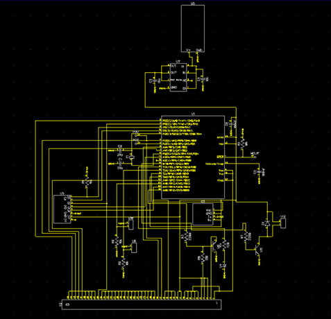
Figure 19: PCB Schematic:
Cost Breakdown:
|
Part |
Source |
Quantity |
Unit Price |
Total Price |
|
MEMS 32kHz oscillator |
Digikey |
1 |
$2 |
$2 |
|
128 x 160 1.8’’ touchscreen |
Display Module |
1 |
$11.19 |
$11.19 |
|
45 position Flat Flex connector |
Digikey |
1 |
$2.82 |
$2.82 |
|
Various discrete components (BJTs, Capacitors, resistors) |
Digikey |
N/A |
N/A |
$2 |
|
Pic32MX250F128B |
Digikey |
1 |
$4.32 |
$4.32 |
|
Circuit Board |
Osh Park |
1 |
$6.7 |
$6.7 |
|
600mAh LIPO Battery |
Digikey |
1 |
$19.43 |
$19.43 |
|
4 GB Micro SD card |
Adafruit |
1 |
$7.95 |
$7.95 |
|
Voltage Regulator |
Digikey |
1 |
$0.50 |
$0.50 |
|
SD breakout board |
Adafruit |
1 |
$14.95 |
$14.95 |
|
LIPO battery charger |
Sparkfun |
1 |
$7.95 |
$7.95 |
|
Total Cost |
$79.81 |
References
2) Oshpark
6) Tahmid’s blog- touch screen
Acknowledgements:
I would like to thank Bruce Land for his help and guidance throughout the semester. I would also like to thank the TAs for their vital support, particularly Syed Tahmid Mahbub.