The idea of this project is to design and implement two channels surface EMG signal controlled video game. The player controlls the motion of the ball to the left or right to avoid the descending obstacles. Electrods will be placed to the back of the player's hands to measure the voltage difference of the muscles when squeezing the hands. The signal will be filtered by a bandpass filter and amplified before sending to the ADC channels of the PIC32 microcontroller. A valid hand motion will allow the player to move the ball to win the game.
Video: Game Demonstration.
High Level Design top
Rationale and Inspiration
Electromyography (EMG) is the measurement of muscle activation via electric potential. EMG has wide range of applications in medical research, robotic controls and other fields. The inspiration of the project came from an interest in EMG signals. I want to better understand the signals generated by our muscles while making varies gestures, and use the signal for video game control and create a unique gaming experience.
Overview
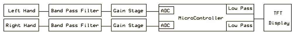
The amplidue range of EMG is from 0 to 10 mV prior to amplification, and the frequency range is from 5Hz to 500Hz, while the dominant signals are around 10Hz to 150Hz. The bandpass filter is desinged to low pass below 250Hz and high pass 10Hz signal since very few signals exceeding this range, and the gain is set to 100. The amplified and filtered signal is then passed into analog to digital converters on the PIC32 microcontroller. The ADC is set to sample signal at the frequency of 2000Hz. Each channel is read at 1000Hz which is more than enough to avoid aliasing.
The EMG signals varies from person to person, and slight change in position of the electrode will change the reading of the signal. Therefore calibrating the signal to center at the same level prior to starting the game is essential to signal detection. The games starts with 10 seconds of calibration, when the calibration is over, the game interface will be displayed automatically and the players can start moving the ball around by making a fist.
Hardware Design top
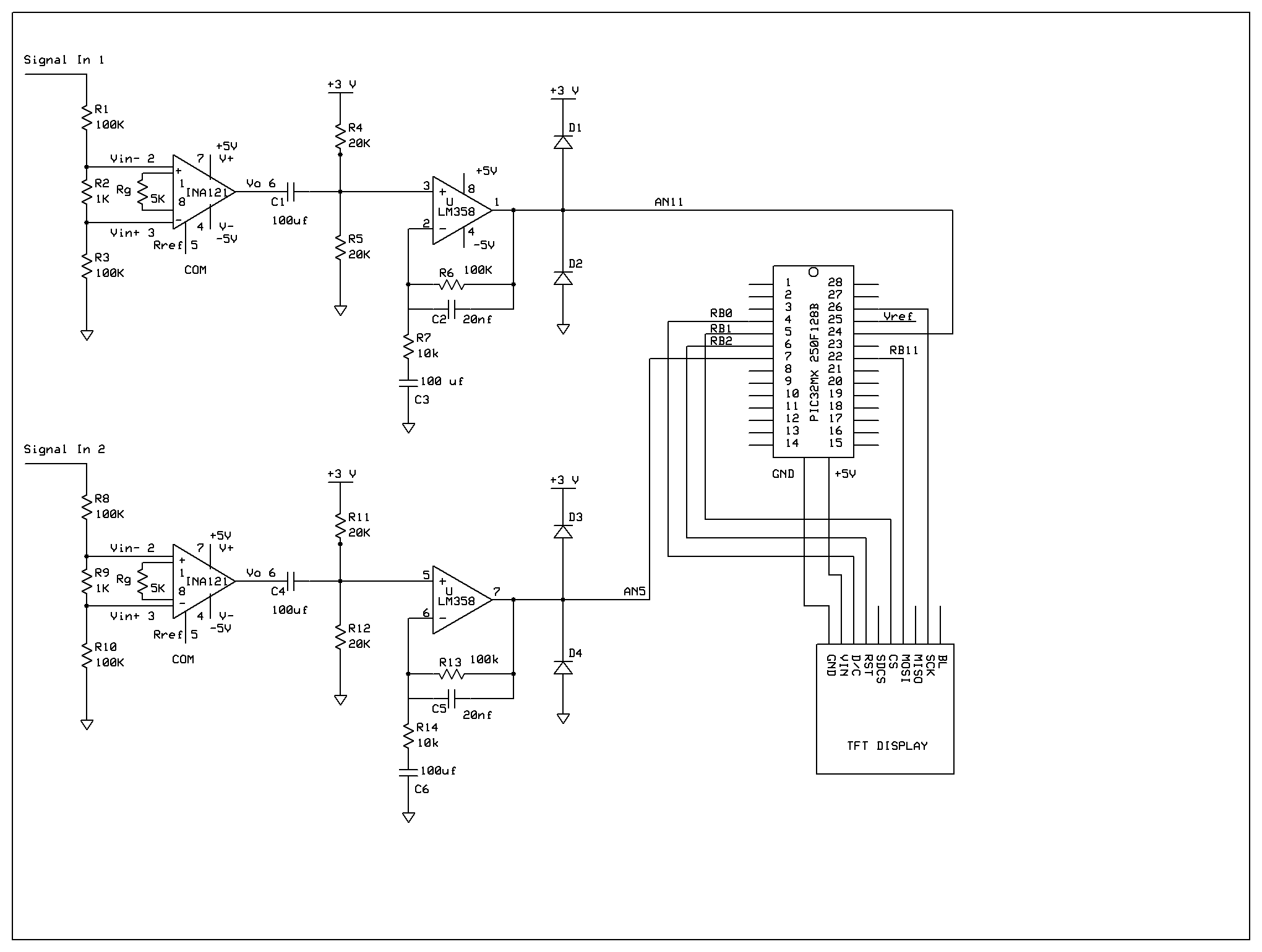
The circuit schematic is shown below. The INA121 chip is a differential amplifier which will measure the differences between the two electrodes placed on the player's muscle. The gain is set to 10 at this stage (gain = 1+50ohm/Rg, where Rg is choosen to be 5k ohm.) The gain in next stage is also set to 10 (R6/R7 and R13/R14) so that overall gain of 100 is ahieved.
Schematic
Results top
Appendices top
Appendix I. Source Code
The full code for our project could be found in SoundNavigation.zip. The two main files used in the final project is SoundNavigationFinal_main_commented.c and lsm303d.c.
Appendix II. Schematics
Appendix III. Cost Considerations
| Component | Number of Component | Cost/Component | Total Cost | Source |
| Microstick | 1 | $10.00 | $10.00 | Lab rental |
| Solder board | 2 | $2.50 | $5.00 | Lab rental |
| Power Supply | 1 | $5.00 | $5.00 | Lab rental |
| TFT | 1 | $10.00 | $10.00 | Lab rental |
| Wires | 4m | $20.00/46m | $2.00 | Lab rental |
| Capacitor | 156 | $0.05 | $7.80 | Lab rental |
| Resistors | 1 | $10.00 | $10.00 | Pomolu |
| Headphones | 1 | $0 | $0 | Donated |
| MIscellaneous | $0 | $0 | Lab | |
| Final Project Cost | $90.70 | |||
Table 2: Cost Considerations
Appendix IV. Team Member Tasks
Abdu - Compass, GPS, code integration
Sophia - Sound synthesis, perfboard/wiring, code integration
Vance - GPS, Buttons, LCD display
References top
DataSheets
- TFT Data Sheet: https://www.adafruit.com/datasheets/ILI9340.pdf
- PIC32 Data Sheet: http://people.ece.cornell.edu/land/courses/ece4760/PIC32/Microchip_stuff/2xx_datasheet.pdf
- LM358 Data Sheet: http://www.ti.com/lit/ds/symlink/lm2904-n.pdf
- INA121 Data Sheet: http://www.ti.com/lit/ds/symlink/ina121.pdf