ECE 4760: Targeting System
Tyler Thompson (tt395) & Steve Slaughter (sts55)
A PIC32 Powered autonomous targeting system that identifies a target and fires a laser at it. Created for Cornell University ECE 4760. See other projects here.
Logical Flow
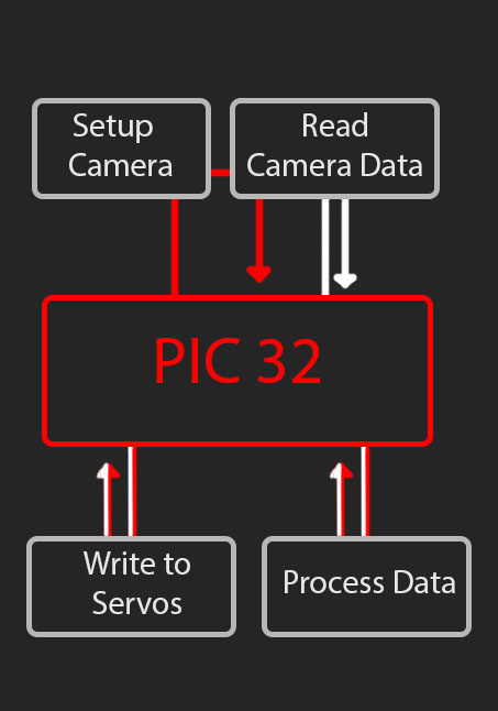
The left indicates the basic logical flow through the device. The red path is followed on the first iteration, the white indicates any further iterations.
- Setup Camera
- Read Camera Data
- Process Data
- Write Servos
- Read Camera Data
- Process Data
- Write Servos
Red Path
White Path
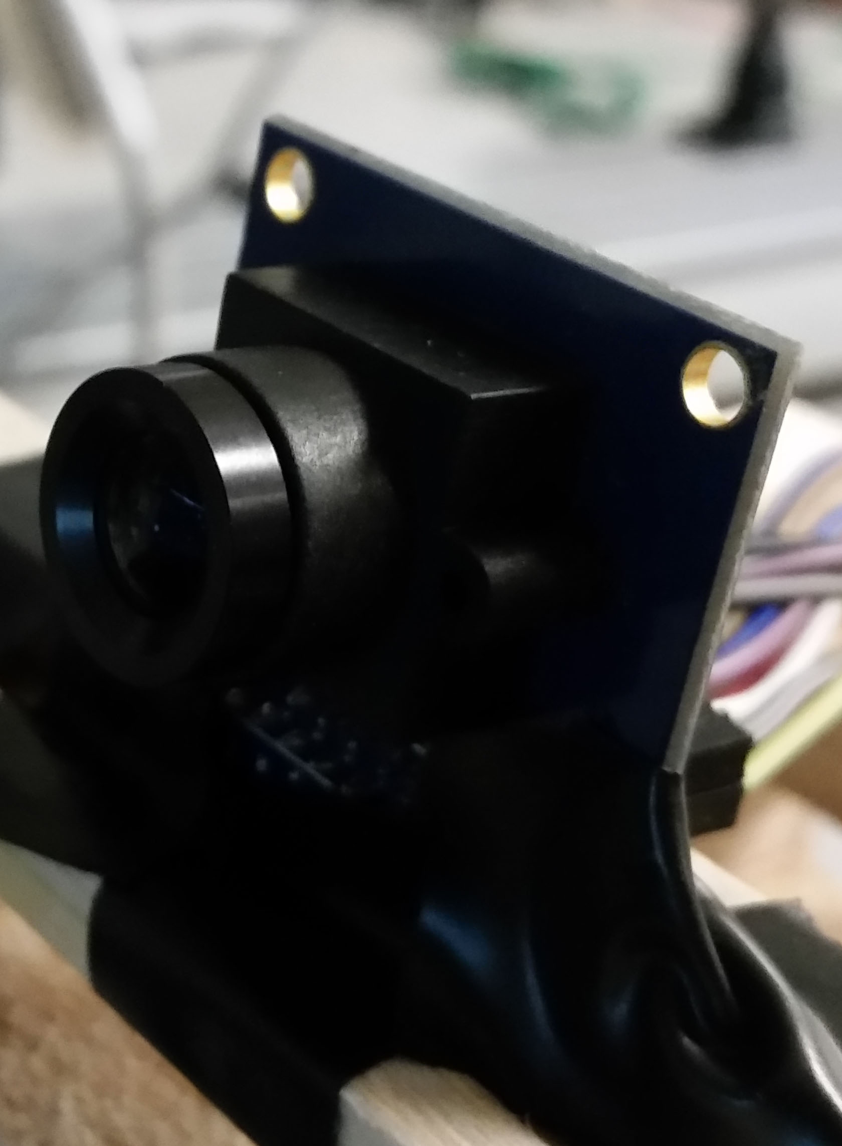
Camera
The camera utilized was an OV7670. This camera is a CMOS image sensor that is fairly commonly used. Cameras are not often utilized with PIC32's due to their contraints on size and speed, but we saw this as a challenge, especially with the lacking amount of documentation available.The standards that are applicable to the camera include: SCCB[1]SCCB (Serial Camera Control Bus) is a protocol defined and deployed by OmniVision Technologies Inc. for control of most of the functions in the OmniVision’s family of CAMERACHIPTM sensors.
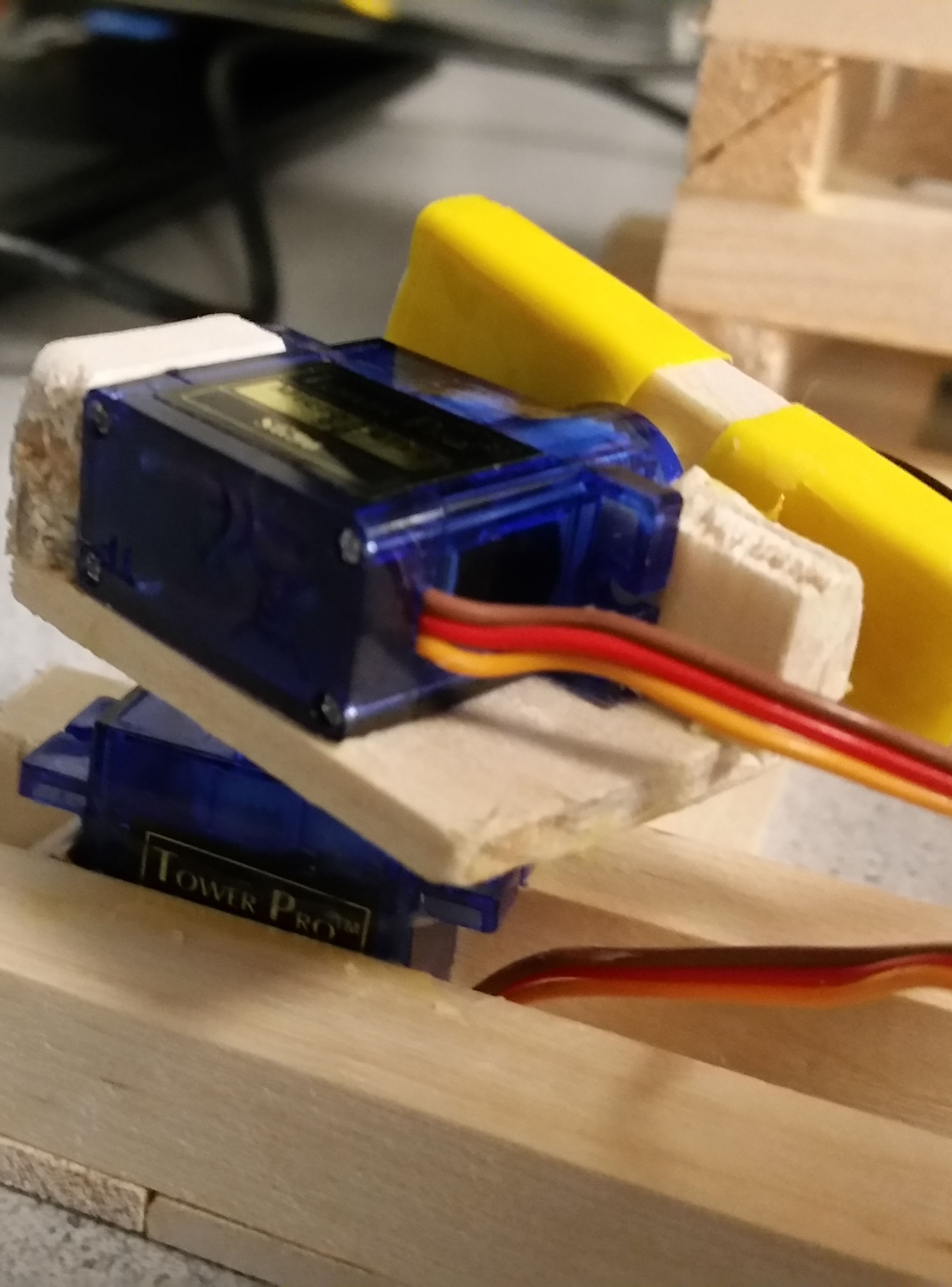
Aiming Mechanism
The aiming mechanism utilizes 2 J-Deal SG90 Micro Servos to create a 2-Axis Pan and Tilt mount system that houses a WYHP 6mm Mini Laser Diode. One concern with using a laser was the focus amount and the ability to control it. The laser diode came with a variable lens, so this allowed us to focus it into a small beam for our desired outcome.The standards that are applicable to the laser include: ANSI Z136[2]ANSI Z136 are the standards for the "safe use" of lasers.
Camera
Why a camera?
Our original intention was to develop a system that could identify a certain target within a very messy background, this meant that we needed to know all of the information in front of it, leading to the only device we could think of being a camera. The camera had to be driven by a microcontroller, so we looked towards a CMOS sensor and eventually ran into the OV7670. After some research we found that it would have many complications with selection, but we felt that we were up to the challenge after seeing some others have success with other microcontrollers.
PIC32 Limitations
The OV7670 utilizes a parallel output across 8 pins, this meant that within the time cycle that the data is available we must pull all of the data using the PIC and be ready for the next set of data in a very short timeframe. We also needed to store the data somewhere, with the data taking up 2 bytes of data each (rgb565 format, detailed below). The Native resolution of the camera was 640x480 this would result in 640*480*2 = 614kB... which is much higher than our available 32kB of data on the microStick II. This meant that we needed to find a way to change the resolution if we were to have any chance to grab all of the information off the camera. This is where SCCB came in.
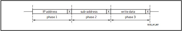
SCCB
After some research we identified that the method to write to the registers of the camera was to utilize SCCB, a communication protocol created by OmniVision. When researched, it was found that many people had different opinions and approaches to dealing with SCCB, some considered it just I2C with a different name, and others said it was close to I2C, but not close enough to use the same methods. With this, we took an initial approach and tried just using I2C with no luck. This meant that we needed to understand SCCB and be able to write our own methods to communicate using SCCB. The overall idea that we found is that SCCB is basically I2C with out acknowledgements. The 9th bit on the byte of data that is usually an acknowledgement is just a "Don't Care" bit.
- Write the prescalar for the pixel clock to 128, this meant that on each pixel we would have 128 times the frequency of XCLK to access each bit, 128 being the max. This was done to give us the best chance of grabbing all of the data.
- The default output format is VGA which is 640*480, this is extremely large for what was desired, and so we switched it to QCIF, which is only 176*144 Now, if the math is done 176*144*2 = 50.1kB which still puts us above the data size on the PIC, but if we only grab every other X pixel we instead push the effective resolution to 87*144, which 87*144*2 = 25kB which fits on our PIC! In order to change the resolution we also needed to set a second register that enabled scaling.
- Next we had some odd results and so we found out that our camera's default was set to an inverted mode. To deal with this we wrote to the register to make sure that it was set to the normal mode.
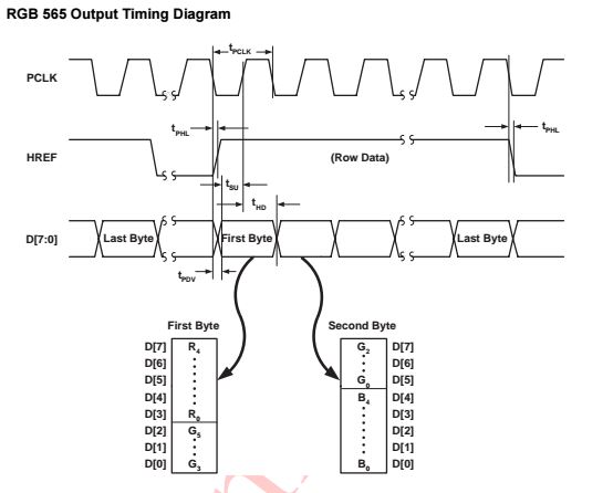
- We wanted to grab all of the color data from the camera, and because this was being output to a TFT display for development testing purposes we wanted to utilize the least amount of conversion. The TFT displays color using rgb565 where the color is split up over 2bytes, with the first 5 bits representing red, the next 6 being green, and the last 5 being blue, hence the name rgb565. This meant if we set our camera's output to rgb565 we would not need any additional conversion.
- As we will look at next, the signal for PCLK is designed to be continuously running. We did want this as it would mess up our control sequence of grabbing all the data , so we set it to not toggle during a horizontal break.
Wiring the camera
The camera overall had 16 pins, 2 of them being ground and power, because the microStick II outputs 3.3v we were able to use only the PIC to power the camera.
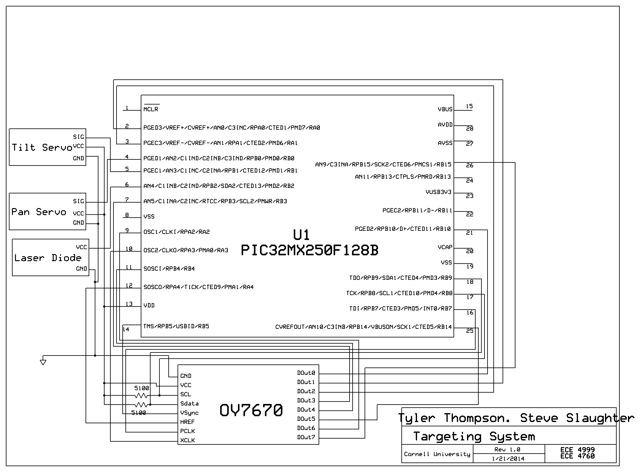
- 21 : D0 - Pin that output the data for digit 0
- 2 : D1 - Pin that output the data for digit 1
- 3 : D2 - Pin that output the data for digit 2
- 7 : D3 - Pin that output the data for digit 3
- 11 : D4 - Pin that output the data for digit 4
- 24 : D5 - Pin that output the data for digit 5
- 9 : D6 - Pin that output the data for digit 6
- 26 : D7 - Pin that output the data for digit 7
- 12 : HREF - Pin that indicated an active row of pixels. Active High
- 14 : VSYNC - Pin that indicated the start of a new image. Active High
- 16 : PCLK - Pin that indicated start of a new byte of data. Active High
- 10 : XCLK - Pin that took in the clock input to drive the camera
- 17 : SCL - Clock pin for SCCB communication, had a 5.1k pull-up resistor
- 18 : Sdata - Data pin for SCCB communication, had a 5.1k pull-up resistor
Pin Connections(Pin Microstick II : pin ov7670 - description)
Data Configuration
The output format of the camera can be RGB 565/555/444, YUV(4:2:2), or YCbCr(4:2:2). We originally wanted color and so we looked
towards rgb565 to getting a proper output. We looked towards the data sheet to see the correct output pattern of the camera based on rgb565.
This can be seen below as detailed by OmniVision.
Aiming Mechanism
Why this method?
Our initial intention was to use something such as a nerf-gun for hitting the target as it would be very entertaining, but constraints of being a class project prevented us from utilizing a projectile weapon. We still wanted a method of "hitting" the target, so we turned to a laser, that when controlled in the correct manner, is safe for use. This also meant we had some standards to abide by, which were thought of in the design of the mechanism.Next we needed to actually aim the laser, we only needed to aim horizontally and vertically and did not care about the rotation of the laser and so decided on designing a 2-axis tilt/pan mount. We wanted it to be very small so that the laser could basically be treated as a point source, but it also needed to be accurate, so we decided upon taking small servos and connecting them to provide the functionality of the 2-axis rotation to the laser.
The laser and servos were connected to the PIC32 using the following wiring connections, with power and ground to the servos being provided by the pic, as well as the ground of the laser:
- 4 : Signal Servo Pan - Controls the panning of the mechanism
- 5 : Signal Servo Tilt - Controls the tilting of the mechanism
- 6 : Laser Power - Turns the laser on and off
Pin Connections(Pin Microstick II : pins - description)
Data Configuration
After some tinkering with the servos and research, we found that in order to control the servos, we needed to send signal with a 20ms duty cycle. The signals needed to be high for somewhere around 600us to 2500us, depending on the desired rotation amount. 600us being all the way in one direction and 2500us being all the way in the other direction. This needed to be repeated until the servo reached it's final position. The laser was much easier, it was on with a high signal, off for a low signal.
Calibration
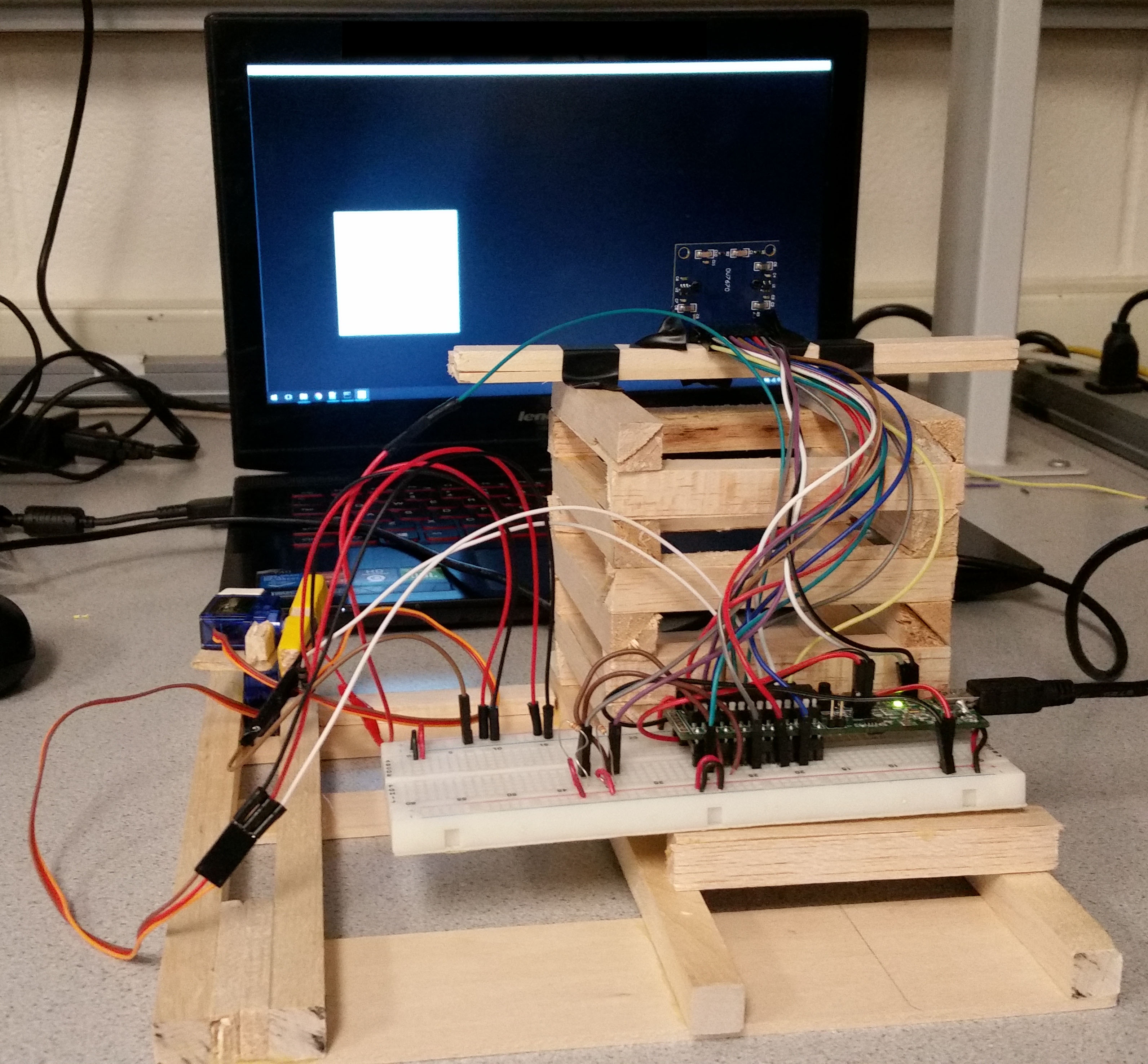
In order to correctly aim our laser at our target we needed to create some consistency to do some calculations from. This resulted in us constructing a casing for the camera, the aiming mechanism, and the microcontroller, as seen below:
Calibration was then completed by writing to the servos and finding the outputs needed to hit the 4 corners of the screen. These were identified to be (pan, tilt): (1520, 1775) for bottom left. (1520, 2060) for top left. (1088,1975) for top right. (1088,1775) for the bottom right. From this information and the information from the camera, we were able to aim at the target and fire upon it, this is detailed in the next section on processing the data.
Data Processing
Targeting Program
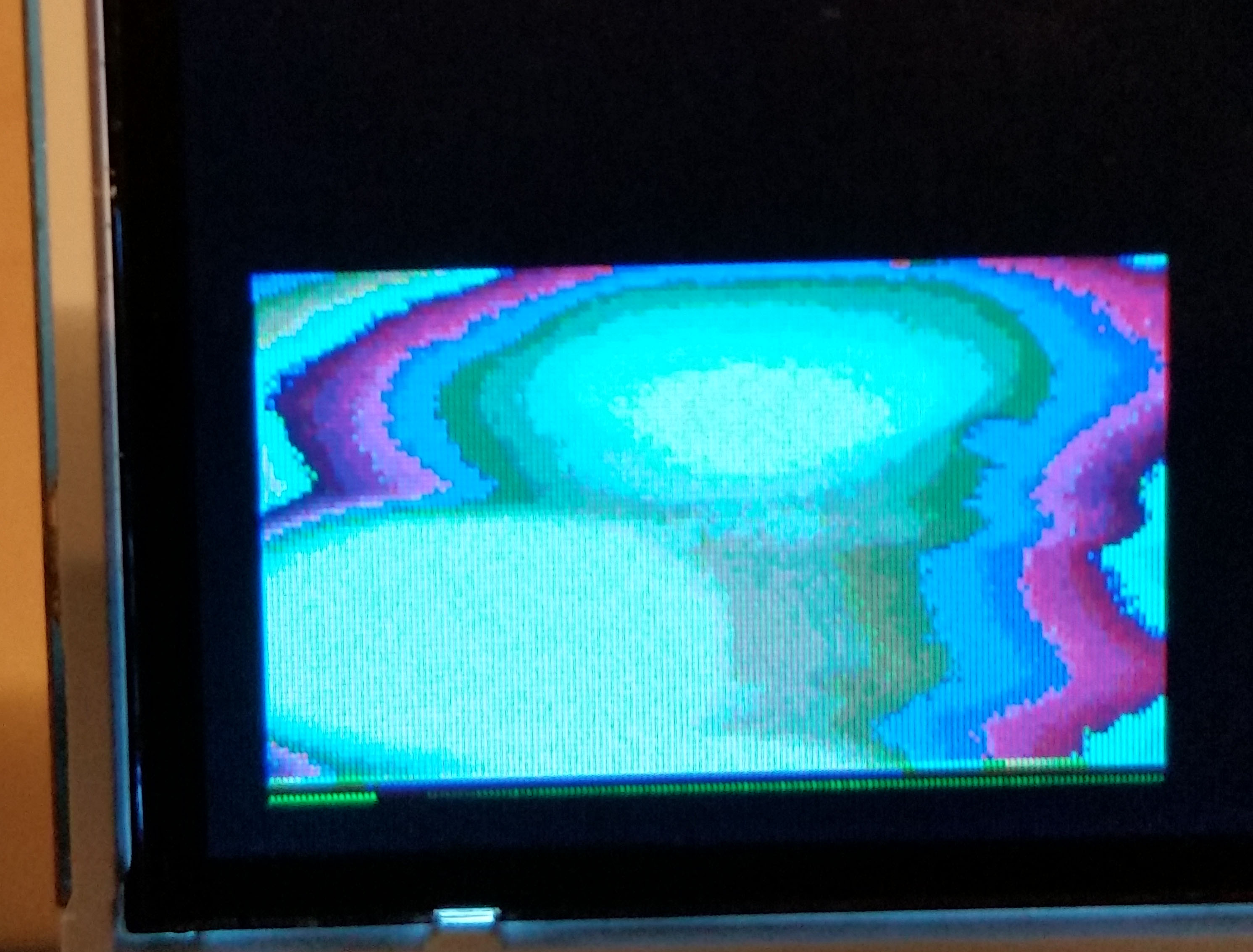
A program was written in python that randomly generated white squares on a black background, which functioned as targets for our system. This served a few purposes. First of all, it forced the laser to be shot at an inanimate object that was not sensitive to a laser and would prevent anyone from being hit by the laser, providing the much required safety of working with a laser. In addition, our camera and it's artifacting seemed to show a pattern. The white tended to be mostly white on in our data, albeit extremely distorted, and anything else tended to be extremely artifacted. From this, we took the approach of finding the only bits that are white in the data and ignoring the rest in order to find the target.
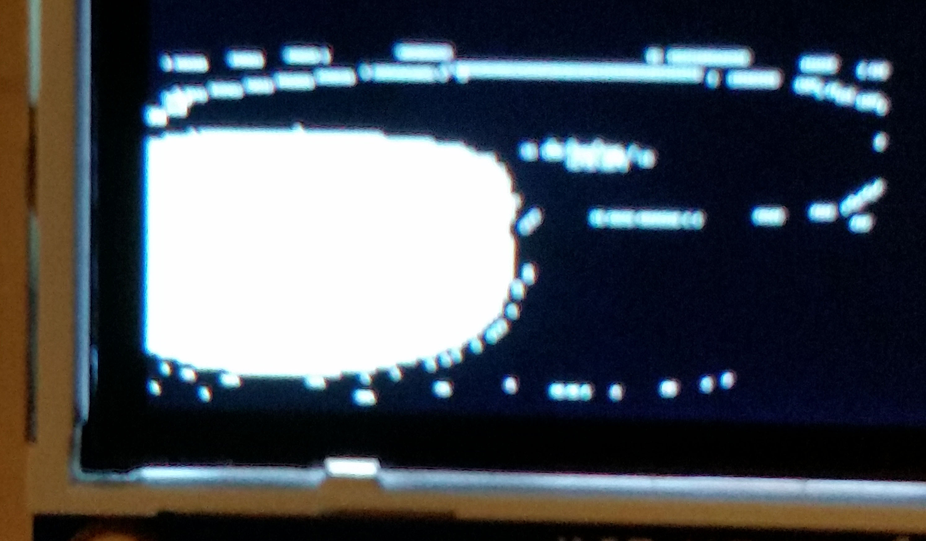
Thresholding
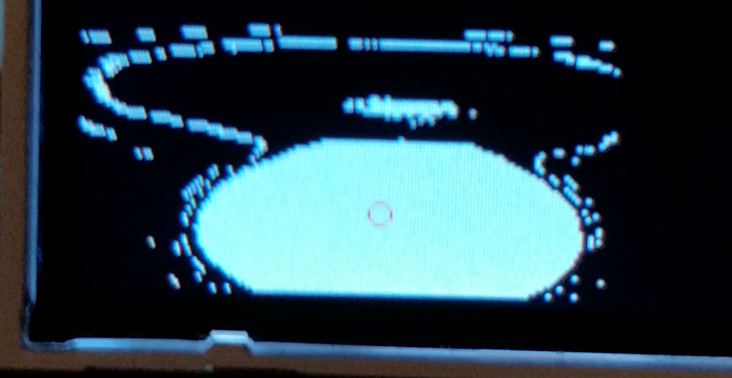
Our approach of getting only the white was built upon that fact that white is equivalent to and rgb565 of 0xFFFF. This meant that if we thresholded the image to white if the data was above 0xF800 then we had a decent result of only showing the white portion of the data. This can be seen below.
Centroid
From the thresholded data, we needed to "find" the target. This was completed by looking at the data, and for each pixel that was still white, the X and Y value were summed. Then when the entire image was looked at, the summations were divided by the number of points still white, this resulted in getting the average X and Y values of the white pixels in the image in order to find a possible centroid. This can be seen on the displayed image as indicated by a small red circle.
Persistence
Now, we know that the image has an insane amount of noise and is extremely succeptible to light changes. This meant that we needed to design a system to be able to deal with this. Our idea was to make sure that there is a target as the location by keeping track of the current marked centroid and the centroid from the last frame. If these centroids were within 10 pixels of each other in the x and y direction, then the system would make an attempt to hit it with the laser. Otherwise the target is unsure and therefore the laser was shut off.
Aiming the servos
Now that we had an idea of an X and Y pixel location, we needed to actually write the servos to aim the laser. This was done using a somewhat arbitrary calculation. With the large amounts of distortion of the camera and the fact that the laser was in the corner of the laptop, we had to take two non-linear functions that we did not know exactly and try to line them up. The x values on the image matched with the y value of the servo, and the y value of the image matchd with the x value of the servo.The initial approach was to base both sets of data off the bottom left being "0,0" and then treating them as linear from there, changing the servo amount by the same percentage of the x and y as the centroid compared to the overall data. This worked decently, but had a lot of misses. The next approach was to attentuate the centroid in order to compensate for the distortion. This was done by multiplying pixel values by a constant. This resulted in the extremes opposite of the servo to be better (but still not that great) while the closer values were terrible. So the image was split up. If passed the center of the image for x, then the x value was attenuated and a value added to push it further right. If left of the center, it was purely attentuated. The y change was slightly different. It was much more non-linear for the servos and therefore needed a different approach. If on the bottom of the image the target is both pushed down a bit and the pixel value is actually divided by a constant to make it have a lower influence. Above the center line it is still pushed down, but the value is attenuated once again. The resultant equations are below (where xTarg is the value for the servo that pans, yTarg is the value for the servo that tilts, xs is the x value of the image and ys is the y):
if(ys > 50){
    xTarg = 1520 - (float)(1500-1088) * (1.-((145.-ys*1.05-30)/145.));
}
else{
    xTarg = 1520 - (float)(1500-1088) * (1.-((145.-ys*1.05)/145.));
}

if(xs > 40){
    yTarg = 1800 + (float)(2000-1800) * (1.-((88. - xs*1.1 - 30)/88.));
}
else{
    yTarg = 1800 + (float)(2000-1800) * (1.-((88. - xs*0.8 - 30)/88.));
}
Results and Conclusion
Video
Errors
Our results ended with around 85% accuracy in non-ideal situations, but would have an extremely low miss rate in an ideal and stable situation. Usually, if the system gets a good reading on the camera, it results in a hit on the target.
Analysis
Overall our results exceeded our expectations. Once we began working with the camera, we were not sure if we would be able to get any form of data, let alone be able to actually use the data in achieving our original goal. Due to the sensitivity to light in addition to the huge distortion of the lens on the camera, we did have locations of our targets that were much worse than others. If a target was generated directly in the center, the distortion would cause it to basically take up the entire screen of data, and this made the centroid almost entirely based on where the light was affecting it. Sometimes this would result in a hit, other times it wouldn't. It also struggled at the extreme edges. We think this is mostly because we didn't actually know where the camera was focused and what was in view, which may have meant the camera was not fully reading the edges. We also can attribute some error to our equation of going from the camera to the servos. If we knew the lens better, we could find an equation for the distortion and be able to just solve the two equations for where they would intersect. If we were to recreate this project, we would try to find a better way of interfacing the camera or looking for a different camera that would allow for a much clearer result for us to gather data from.
Standards
Our only major standard we had to adhere to was also our biggest requirement for safety: the laser. We made sure that the laser was never pointed towards anyone and the code is designed in a way that, assuming the system is being operated correctly, the laser will never point outside of the bounds of the laptop screen.
Intellectual Property
The methods of interaction with the hardware was identified through data sheets accessed online that were referenced earlier in the page. The setup for the device was created by ourselves. The code that was utilized was written by ourselves with header files and souce files for libraries, configuration, and various helper functions being utilized from class files for ECE4760 that were created by Bruce Land and Syed Tahmid Mahbub. Currently no action is being seeked regarding patents or publishing.
Ethical Considerations
Our project adheres to the IEEE Code of Ethics. Our project and the materials used for development were not utilized to inflict any harm or pose any threat to others. The laser on our device is known and it's use is made known to those who interact with the device. The system is created and works in the fashion and to the ability as addressed so far on this site. All work that we have indicated as our own has been created by ourselves, and if not has been referenced to the creator of said information. This project was created as a class project and therefore we are open to any and all honest criticism from others, as well as are willing to assist others with any complications they have regarding our work. This is one of the many projects created for ECE4760, all of which have been linked at the top of the webpage and once again linked here.
Legal Considerations
To our knowledge our project does not violate any legal considerations. All work belongs to those who have been referenced, and if no reference is made then the work is completed by ourselves. All materials utilized to create the system have been purchased by ourselves or used from lab with permssion.
Appendices
The group approves this report for inclusion on the course website.The group approves the video for inclusion on the course youtube channel.
Program Listing
targetingSystem.c glcdfont.c pt_cornell_1_2_1.h config.h tft_gfx.c tft_gfx.h tft_master.c tft_master.h Python Targetting ScriptSchematic
Cost Details
| Name | Vendor | Cost/Unit | Quantity | Total Cost |
|---|---|---|---|---|
| MicroStickII | Lab Stock | $10 | 1 | $10 |
| PIC32 | Lab Stock | $5 | 1 | $5 |
| White Board | Lab Stock | $6 | 1 | $6 |
| OV7670 | Amazon | $7.09 | 1 | $7.09 |
| Mini Laser Dot Diode | Amazon | $1 | 1 | $1 |
| SG90 Micro Servo Motor | Amazon | $3.40 | 2 | $6.80 |
| Jumper Cables | Lab Stock | $.10 | 20 | $2.00 |
| Craft Wood | Hobby Lobby | $8.62 | 1 | $8.62 |
| $46.49 | ||||
References
Datasheets
OV7670 Data Sheet PIC32 Peripheral Libraries for MPLAB C32 Compiler PIC32 Reference Manual PIC32MX2xx datasheet SCCB SpecificationFigures
[1]SCCB 3-phase Transmission Circle [2]OV7670 RGB565 Output InformationStandards
[1]ANSI Z136.1 [2]SCCBWork Distribution
Tyler Thompson
- Project Design
- Software Design - Camera
- Software Design - Image Processing
- Background Research
- Software Debugging
- Hardware Design
- Website
Steve Slaughter
- Project Design
- Background Research
- Software Design - Aiming Mechanism
- Software Design - Python Targeting Program
- Website Proofing
- Hardware Design
- Structure Construction
Contact
Tyler Thompson : tt395@cornell.eduSteve Slaughter : sts55@cornell.edu