Traditional bicycle odometers only display current speed and total distance travelled. The bicycle computer aims to provide data comparable to that of a stationary bicycle, while allowing athletes to ride outside. Ideally, this data will contribute to better interval workouts and regular rides alike. Using a PIC32, we were able to implement a range of features including:
- Programmable splits
- Split recall
- Pedal RPM
- Speed
- Total distance travelled
- Total workout time
- Turn signals
Rationale
During training, many professional and elite athletes rely upon accurate metrics and telemetry to assess their
performance and improve their weaknesses. Most of these systems come with a hefty price tag which precludes the
vast majority of athletes from taking advantage of this type of technology. This exclusionary bias towards athletes
and clubs with the financial means to purchase expensive equipment may mean that many athletes without the same
means find themselves no longer able to compete at the same level.
In an attempt to rectify this, we have created a bicycle computer with an eye for price and versatility. The goal
for our computer is to be cheap enough that any aspiring amateur cyclist can afford it, yet versatile and accurate
enough to have a significant impact on their training. To achieve this, we selected 6 crucial features which give
the user insight about their training, while utilizing only 2 inexpensive sensors.
In addition to our focus on price and versatility, we also wanted our computer to be modular and safe for use on
busy streets. With a modular system, users can easily attach and detach various components, allowing for future
integration of additional sensors as well as easy computer dismantling for competition. As for the safety of our
system on public roads, we ensured that interacting with the computer did not require significant hand movement,
and included turn signals to assist the user in making legal road maneuvers.
Background Math
RPM Determination
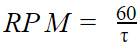
Where t is the time measured via Hall Effect sensors, in seconds.
Speed Determination (mph)
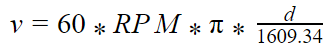
Where d is the wheel diameter in meters
Hardware/Software Tradeoffs
Wheel diameter assumption & speed calculation
One key assumption made in our bicycle model is that the rear wheel diameter is constant. Since this diameter
is used to calculate both speed and distance travelled, any inaccuracies from factors such as tire pressure or wheel
deformation leads to output error. However, this implementation is much cheaper than alternatives such as GPS or a tire
pressure sensor, making it ideal for this system. Additionally, whatever error is present from this assumption will be
constant across a single workout. While this is not ideal for comparing performance across workouts, it does allow the
user to structure their workout correctly, and closely approximate desired splits.
Turning signals
In order to increase the safety of the system, we created the turn signals on an independent circuit, with a separate
power source. This ensures that the turn signals will remain functional in the event of the system losing power or an
unforeseen bug. However, because the turn signals are independent from the microcontroller, they require separate inputs,
and cannot be controlled by the microcontroller. If the turn signals were connected to the microcontrollers, additional safety
features could be implemented, such as blinking “hazards” when the bicycle is traveling slowly or stopped, in order to alert
nearby drivers of the rapidly approaching cyclist.
Wiring
Despite the availability of wireless communication protocols such as bluetooth, we chose to connect our sensors via
wires. This choice reduced the cost and complexity of the system, at the expense of additional steps to attach or remove the system.
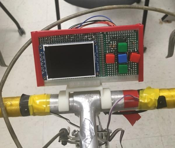
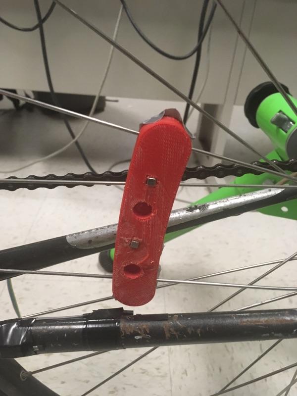
Hardware Design
For our hardware design we just started with an old road bike and added our sensors to the bike frame. We made a mount
which could hold the TFT and buttons on the handlebar between the hands of the rider. We also had to run some wires along
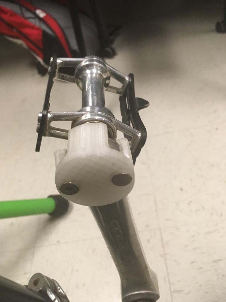
the frame to connect to the 2 hall sensors as well as the turn signals in the back of the bike. The hall sensors are both
located near the bike crank. It is important that the hall sensor lign up with the magnets connected to the crank. There are
also two magnets on the spokes of the rear wheel which also need to be aligned with the sensor on the inner side of the rear
triangle of the bike. There should be no more than about a 10 mm air gap between the hall sensors and the magnets in order to
make the sensors work properly. This distance also depends on the strength of the magnets and might need to be adjusted for best results.
The magnets are placed on the clips that connect to the pedal and also the wheel spokes. Here it is important that the
two magnets are arranged in opposite polarities in order for the hall sensor to work properly and measure one ‘tick’ every revolution.
External Interrupts
External interrupts are utilized to detect when a pair of mangets pass a hall effect sensor. We use external interrupt 0
to detect pedal rotations and interrupt 1 for the wheel. In order to how fast the pedal or wheels are turning, we have
variables to track when the last time the interrupt fired was in milliseconds since startup. We can then subtract this time
from the current time to get how long the previous rotation took. To find rpm, simply take 60,000ms (one minute) and divide
it by how long it took for one rotation. To find speed, we divide a precomputed constant by the time between revolutions.
Finding the constant, however, is much more involved. Essentially, the circumference of the wheel in miles is multiplied
by the number of milliseconds in an hour to comput miles per hour. Incrementing distance with each wheel revolution is
acheived simply by adding wheel circumference in miles to distance. Within the wheel interrupt, there's some additional
logic to handle workout state such as incrementing the split number, switching to recovery, or finishing the workout.
Along with this, the appropriate split is distance is incremented according to workout state.
Timer Thread
For our time keeping, we utilized a thread with a one second yield. This thread was responsible for updating our total
time and split time. If a split time or recovery time was reached, it would transition the workout to the appropriate state.
Additionally, this thread was responsible for keeping the tft up to date. It would clear the previous contents and draw
updated values to the screen.
Button Thread
This thread is fairly simple, but contains a ton of state logic. It runs every 50ms so user input feels crisp. It reads
the inputs hooked up to the buttons and debounces the inputs. The button functions depend on which menu screen is currently
displayed. If the user is configuring a workout, the up and down buttons navigate between options. The left and right buttons
increment and decrement certain workout characteristics. Finally, the center button confirms and begins the workout. With each
keypress, the screen is cleared and new screen state is written. When in the splits or workout menus, the left and right buttons
are disabled, and the up and down buttons are used to navigate between screens containing more splits or more real time
data. Users can switch back and forth between the workout and splits sets of screens using the middle button.
UI Structures
We implemented a variety of structures to help with tracking values and displaying them on the tft. One structure we have
is ui_value. This simply contains two fix16s, one to hold the last value for this variable that was written to the screen,
and one to hold the next value to be written to the screen. The previous value is important for being able to erase the contents
of the tft without clearing the whole screen, reducing flicker. Along with this, we have stack_layout which contains two
ui_value pointers and two function pointers to functions that properly format the values. This stack layout is good for
consistently printing two values, such as speed and rpm, on the same screen while being able to scroll down to another screen that formats
data differently. Finally, we have options_layout and split which simply groups appropriate variables together
such as a time and a distance. The functions responsible for writing this data to the screen are all of the functions prefixed
with "print_". These include sprintf logic for times, distances, rpm, etc.
State Machines
Our code contains two very simple state machines for tracking progress through a workout and which menu the user is viewing. The
workout state machine can be seen below:
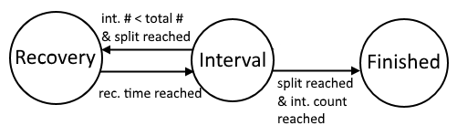
Throughout the workout, the state machine alternates between the interval and recovery states. When in the interval state, the
appropriate split in the split array collects time and distance data. Since recovery time is uniform for each interval, a dummy
time is filled until the state transition is reached. Once the appropriate number of splits is achieved, the workout state switches
to finished. If split count is left to 0, the state machine will alternate between interval and recovery indefinitely.
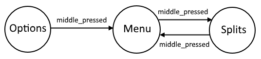
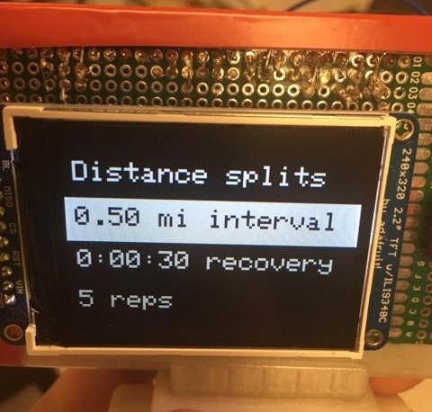
The first menu is the options menu where users configure their workout. Once the workout is configured and okayed, the user immediately
begins the workout. In this state, users can view real time statistics such as speed and pedal rpm. During the workout, the user is
free to switch between viewing the real time data and previous splits by pressing the middle button.
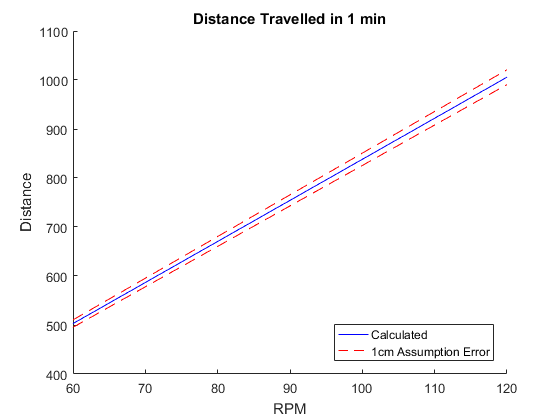
Over the course of a single minute in the highest gear, an error in the wheel diameter assumption can result
in as much as 15 meters. While an athlete will likely not be pedaling at 120RPM while in the top gear for an
entire workout, even pedaling at 90RPM in a middle gear can result in 8 meters of error. So, over the course
of a typical hour-long workout, an error in wheel diameter of just 1cm can add up to ~500m of error in distance travelled.
We attempted to minimize screen flicker by only clearing previously drawn text rather than the whole screen. We
were only able to do this for the real time data screens which update every second. The workout configuration
screen and split recall screen relied on writing the whole tft to black before writing new text. Updates on these
screens provided a large amount of flicker, but these screens updated so infrequently (ie whenever a user pressed a
button) that it wasn’t a nuisance.
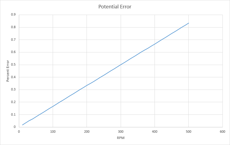
We initially looked at using an input capture to get clock cycle accuracy on wheel and pedal revolutions. We
soon realized that revolutions happen too infrequently for this to work. We then settled for using the protothreads
milliseconds counter to time events. This turned out to be much more suitable and easier to implement. However, as
you speed up, accuracy degrades. The change in error can be visualized below. Speeds of 40 mph can reach wheel
rotation speeds of around 500 rpm.
Possible Improvements
The design performed as expected when it comes to being used as a tool for workouts, however, there is tons
of opportunity for improvement. A stretch goal we
missed was the ability to analyze a user's force throughout each stroke. We realized it would be a huge
effort to implement, and didn't have enough time to add it after finishing user defined splits. Another cool
feature to add could've been automatic headlights to compliment the addition of turn signals.
Perhaps the lowest cost addition with highest gain would've been some way to automatically retreive workout
splits. This could be through logging to an SD card or even a bluetooth interface. If we went the route of
bluetooth, the whole TFT and buttons could've been swapped with a phone. In this case, the PIC32 would act
to gather sensor data and relay it to a smartphone app. A smartphone would likely be much easier for viewing the
data and having finer control over workouts.
Existing Patents
Within the realm of mountable bicycle computers with peripheral sensors there are at least two existing patents
on similar technology. The first is US Patent No. 6192300
B1 which describes the use of multiple microprocessors
and a plurality of sensors to determine the bicycle speed and pedal RPM, among other quantities. Another is Patent
No. 0887252 B1, entitled “Bicycle Computer with
Cover”, which covers the mounting of a computer to a structural
member of the bicycle. It also specifies a cover which swings to allow the user to view the computer. Both of these
patents are filed by Shimano Inc., a prominent company within cycling technology.
Ethical Considerations
Considering that this project was meant to be used while riding on the road, safety became a large consideration.
One way we achieved this was through ensuring that the user interface was easy to read and interact with. We
intentionally used large text on the screens users would interact with while riding. Smaller text was permitted on
the workout customization screen and split recall screen because it was assumed users would view these screens
while stopped, ie. before and after the workout. Button placement was such that riders would not have to remove
their hand from the handlebars in order to interact with the computer. This ensures users remain stable while
riding and don't have the distraction of looking down to find the buttons. In addition, we improved general
cycling safety with turn signals so it's very clear where the cyclist is intending on turning.
In accordance with the IEEE Code of Ethics, we continually consulted the TAs for feedback on the project
and asked for ideas for how to make it better. During development, we debated the accuracy limitations of our
implementation and determined that even under extreme use cases, the data was accurate enough to provide a
controlled workout. All fixtures consist of plastic clips which would not damage a user's metal bicycle.
Legal Considerations
There are no legal considerations relevant to this project.
Appendix: Approvals
- The group approves this report for inclusion on the course website.
- The group approves the video for inclusion on the course youtube channel.
main.c
ui_layout.h
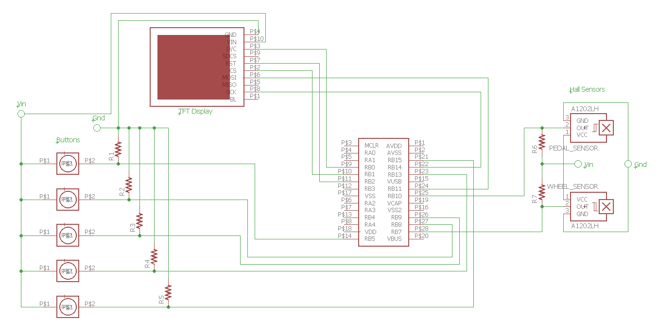
Appendix: Schematic
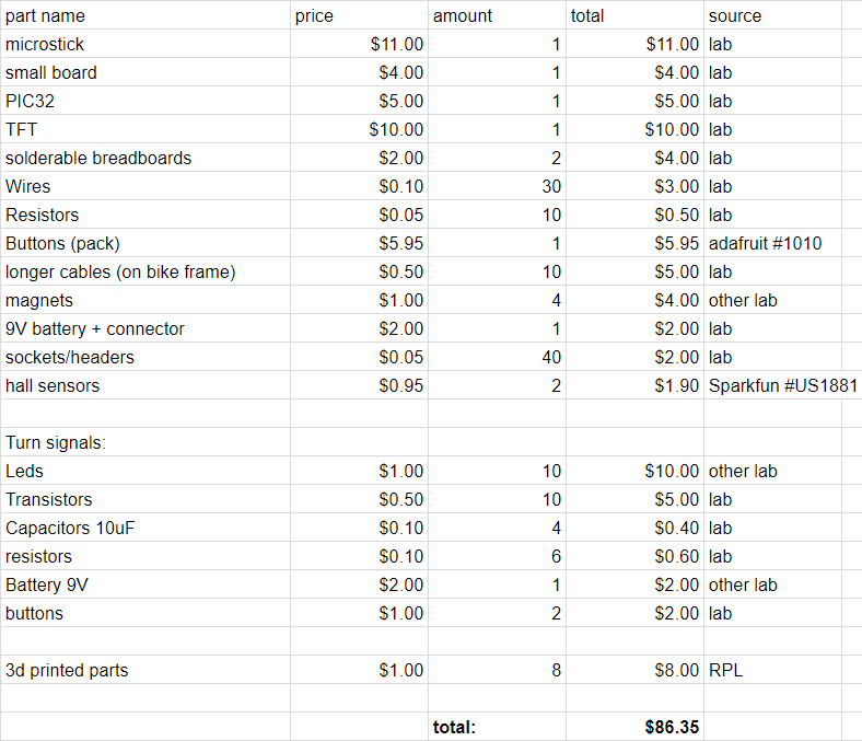
Appendix: Budget
Appendix: Task Division
Gabe
- Report writing
- Sensor integration
- Timeline & Milestone
- UI design
- Report writing
- UI coding & design
- System architecture coding
- Report writing
- Turn Signals (circuit and hardware/attachment)
- Soldering and wire handling
- Hardware mounting (CAD/3D printing)
Appendix: References
PIC32 datasheet
Peripheral library guide
Hall effect sensor datasheet
555 timer blinker circuit
IEEE code of ethics