Peter Moegenburg
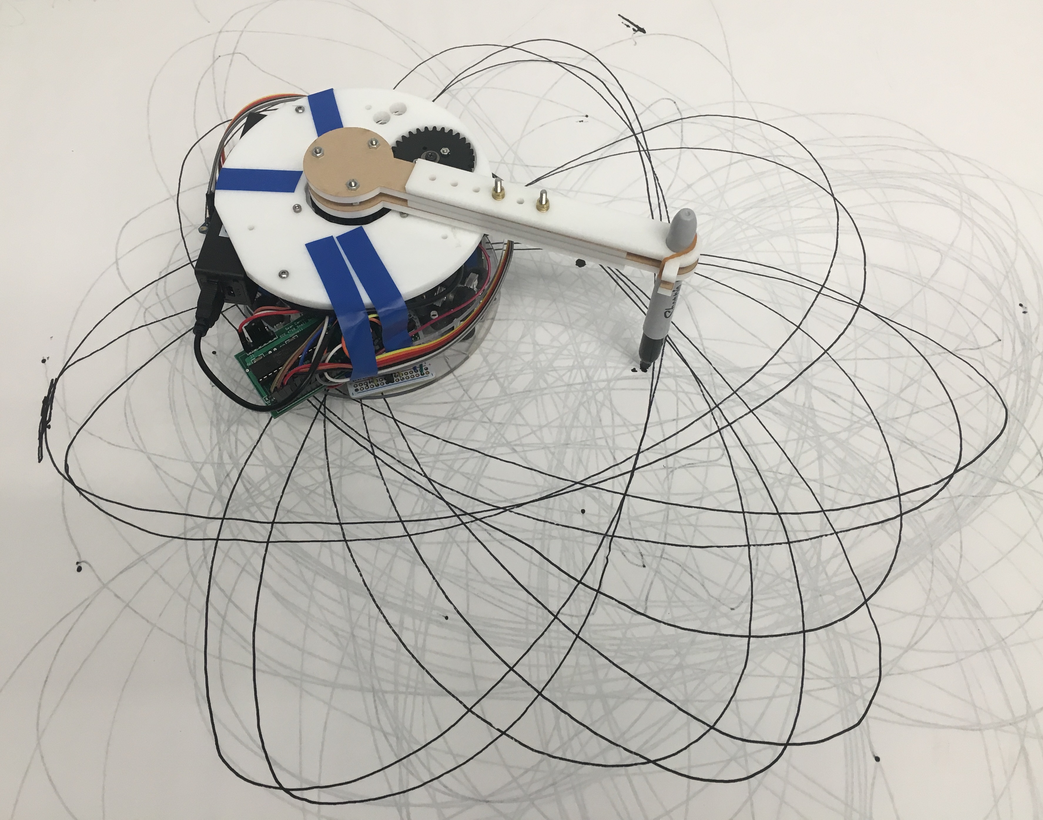
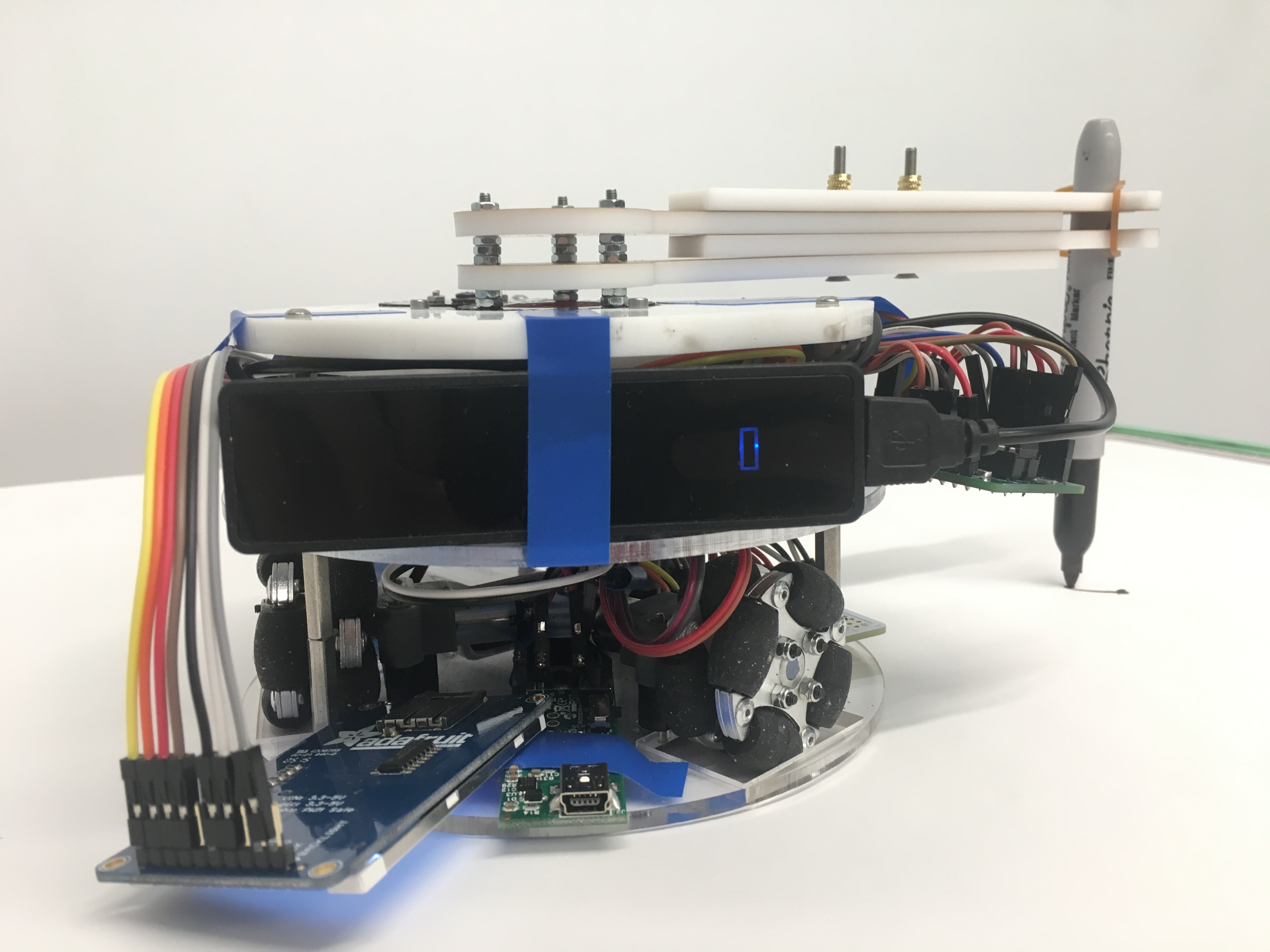
The SpiroBot is a mobile drawing robot with a holonomic drive and drawing arm capable of creating a variety of patterns on a floor or tabletop canvas.
SpiroBot was born out of a desire to show that robots can be fun, interactive, and more than just productivity assistants. I wanted to show that robots can aid in creative activities and improve people’s creativity by opening their minds to transformations and abstractions of their input. This robot may have many drawing and other applications, but the specific application for this project was the creation of spirographs, the drawings produced by the drawing toy Spirograph since its introduction in 1965.
These drawings are created via an outer gear frame and an inner gear that rotates about this gear frame. A user draws a spirograph by inserting a pen into a hole in the gear and moving the gear around the frame while keeping the frame stationary. There are some interesting characteristics about the setup of this toy. Firstly, the center of the gear moves in a constant-radius circle. Secondly, the gear rotates at a constant rate about it’s center. Thirdly, the pen maintains a constant distance from the gear center. Fourthly, the pen rotates at a constant speed about the gear center. These relationships formed the basis of the SpiroBot’s design. The base of robot mimics the movement of the gear and the drawing arm mimics the movement of the pen with regards to the gear. Together, their movements mimic the Spirograph drawings.
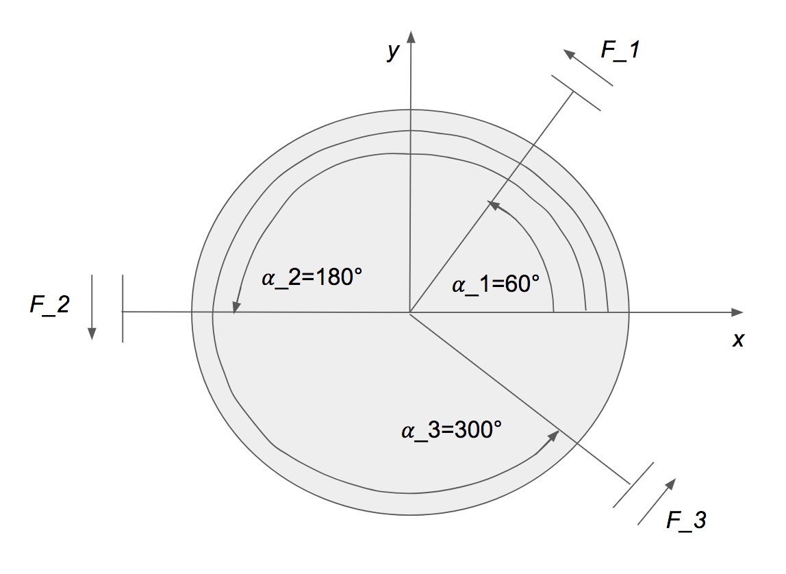
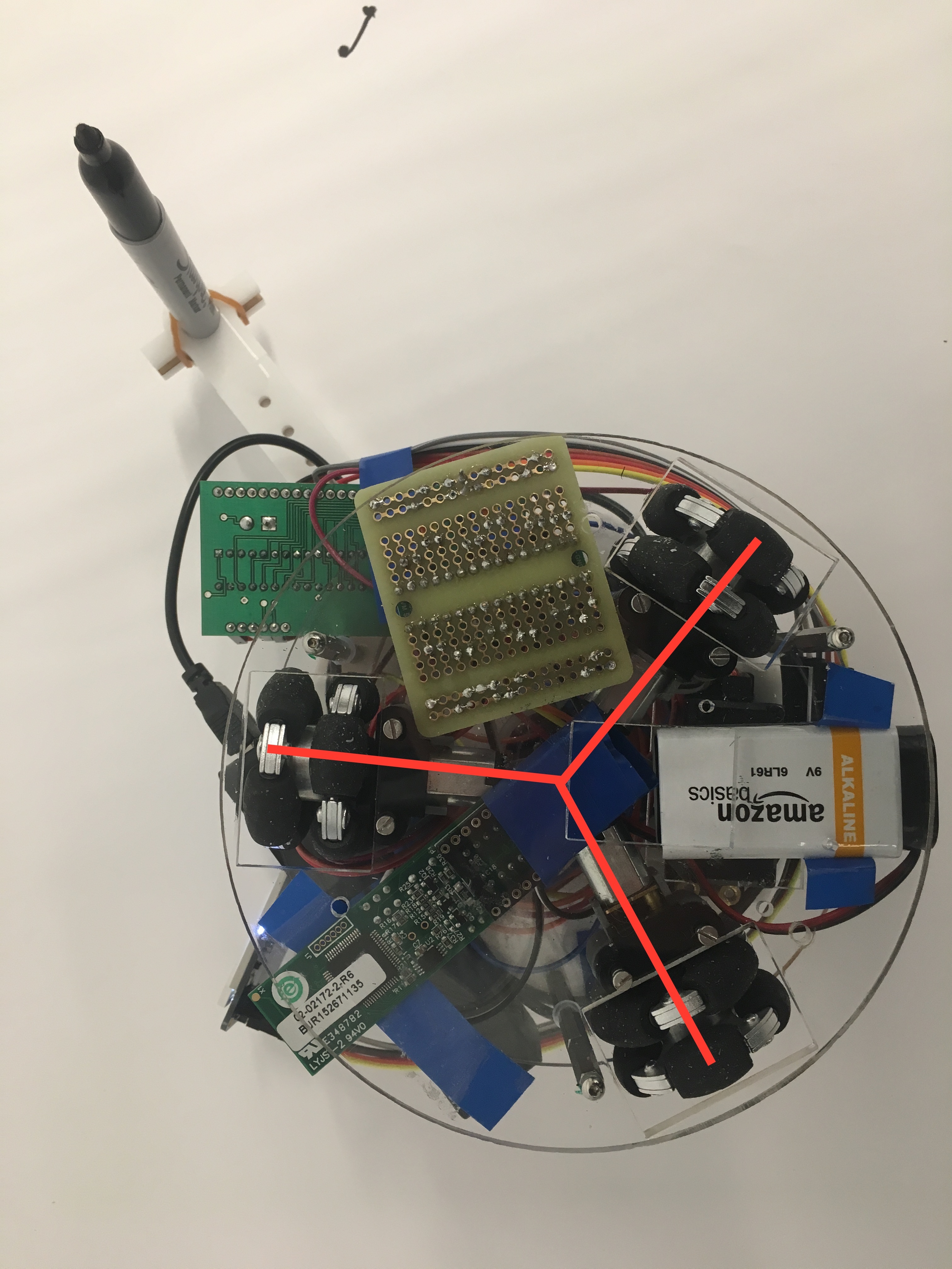
The SpiroBot’s base is outfitted with a holonomic drive via 3 wheels, spaced 120 degrees apart. By controlling the speeds and directions of these wheels, it is possible to move in any direction at any speed within the motor speed range. The theory behind the control of these wheels was adapted from a tutorial found here. The Spirobot’s local coordinate frame and actual base, seen below, are the same setup as this video except it is rotated 30 degrees counterclockwise.
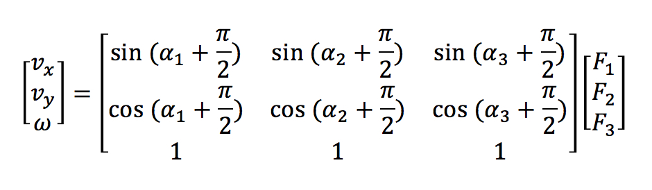
This video tutorial explains how to transform inputs for linear velocities and angular velocity into force outputs for the motors. The system is first defined using by the matrix equation seen below. The transform matrix is then inverted to achieve the desired inputs and outputs. These force outputs from this equation correspond to the speed at which each motor is driven.
The holonomic drive gives the robot superior moving ability and freedom as compared to standard differential drive robots and can be utilized in future applications for the robot. SpiroBot also has a servo motor to move the drawing arm. This arm length is adjustable via a pair of bolts. Adjusting the servo speed and direction, arm length, and holonomic drive parameters allow the SpiroBot to mimic infinite possible spirograph drawings as well as other drawing patterns and motions.
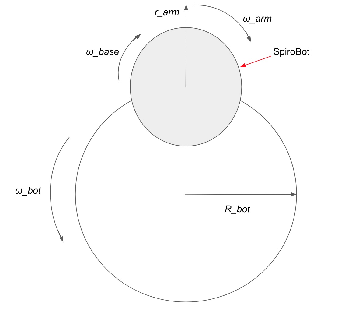
Above is a diagram of the rotations and radii for the components of the robot. To create a spirograph, the bot needs the correct directions and values for these parameters. The parameters ω_bot and R_bot correspond to the rate and radius of the rotation of the Spirograph gear about the center of the Spirograph gear frame, which we’ll call ω_gear and R_gear respectively. The rotation was taken to be counterclockwise for this project. The parameter r_arm corresponds to the distance of the Spirograph pen from the center of the Spirograph gear, which we’ll call r_pen. The parameters ω_base and ω_arm work together to correspond to the rate of rotation of the Spirograph pen about the center of the Spirograph gear, which we’ll call ω_pen. This rotation was taken to be clockwise in this project. The parameter ω_base could have been used with a stationary arm on the robot to create a successful SpiroBot, but this implementation provides more room for future applications. While the values of all of these parameters may be adjusted to create different types of spirographs, the sign of ω_gear and ω_pen must oppose each other to create a successful spirograph. The various means for adjusting robot motion parameters to achieve desired spirograph drawings is discussed in the Software Design section. The various successful values for these robot motion parameters is discussed in the Results section.
No standards from IEEE, ISO, ANSI, or DIN were used. No patents, copyrights, or trademarks were infringed upon as all hardware and software used and referenced in the project is credited.
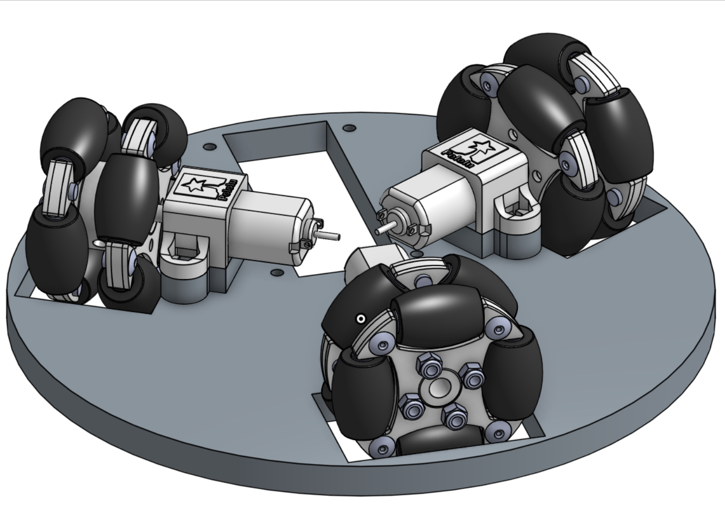
The base of the robot is designed for and constructed with laser cut acrylic. The motor housing pieces are 3D printed due to their form. The motors are positioned 120 degrees apart and their shafts are connected to the omni-wheels. Since I needed to fit a lot in the robot and wanted to keep the robot compact, I minimized the robot’s clearance with the ground via motor platforms. The robot is constructed of tiers, with the second tier stood off of the first, and third tier stood off of the second. The electronics reside on the first and second tier, leaving the top of the third tier free for arm rotation. Parts were designed in OnShape, a cloud-based CAD software, for precise fits and a robust design.
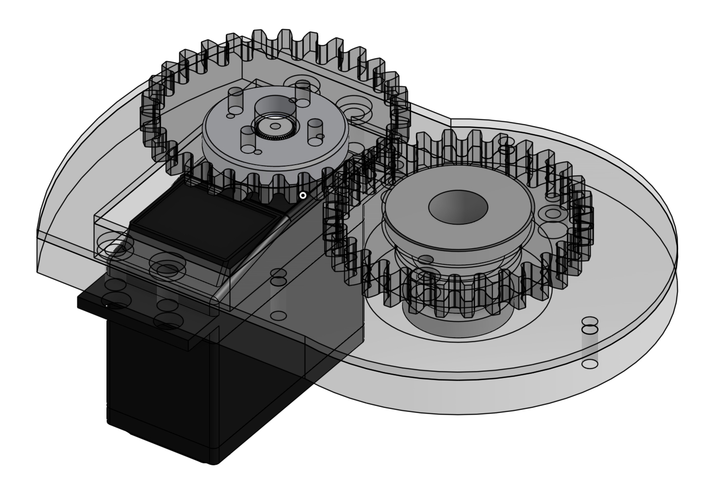
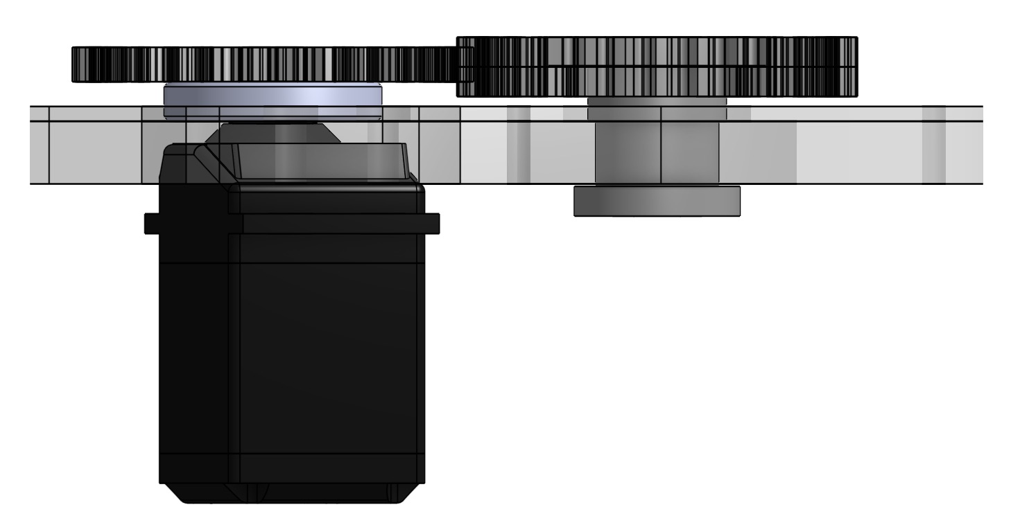
The third tier of the robot is also designed for and constructed with laser cut acrylic. The central bearing hub is 3D printed due to its form. The arm mechanism pulls heavily from the base design of the Blossom robot, from Professor Guy Hoffman’s HRC^2 lab. This project is led by PhD candidate Michael Suguitan, who generously shared the design data as it is an open-sourced project. Many changes for fit and rapid iterations of parts were necessary to maintain the robust design set forth by the base platform. A servo motor is fixed to the bottom of the third tier and the motor gear is attached to the servo hub. A central gear mates with a loose hub, which attaches it to the bearing embedded within the center of the third tier. From this central gear, the arm sprouts and cantilevers off the robot. The gears are 1:1, so the arm is capable of spinning around the platform at approximately 60 rpm. The arm length is adjustable via a pair of bolts. A marker, for this project a Sharpie, fits in the end holes of the arm and is spring-loaded to make good contact with the drawing surface via a rubber band.
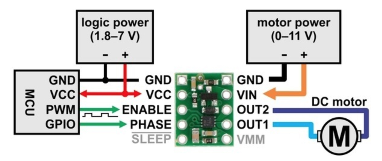
The base dc motors are Pololu 150:1 Micro Metal Gearmotor HP 6V found here. They provide sufficient torque (40 oz-in) and speed (200 rpm) for my project and future purposes, albeit at a high current draw (120 mA no load, 1600 mA stall). They are regulated with the Pololu DRV8838 Single Brushed DC Motor Driver Carrier, whose diagram can be seen below and found here.
The servo motor for the arm is a standard continuous rotation servo found here. This servo provides sufficient torque (~42 oz-in) and speed (~60 rpm) for the arm with a relatively low current draw (140 +/-50 mA no load, 15 mA static). Below is a schematic of the full system.
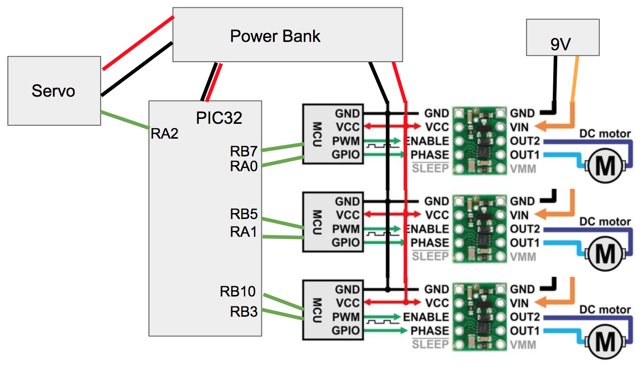
The power for the PIC32, servo motor, and driver logic is supplied by a power bank, found here. The power for the driver motor outputs is supplied by a 9V battery.
The PIC32 microcontroller used to control the robot is the same as the one used throughout this course, but it is implemented in the small board setup from course, detailed here. To program the PIC32, I use the same Microstick2 as throughout the course, also detailed (with described board connections) in the previous link.
The servo motor takes a formatted pwm signal to control its direction and speed. This signal must be 50 Hz with a high signal time of 1.3-1.7 ms and low signal time of 20 ms. To create this signal, first timer2 is initialized at 50 Hz. With a system clock speed of 40 MHz, this is done by setting a timer2 prescaler of 16 and generation period of 53750. To complete the signal, output compare 4 is initialized with timer2, the pwm fault pin disabled, and the pwm_on_time4 variable. This variable falls in the range of 3250-4250 to correspond to 1.3-1.7 ms pwm signal high times. This pwm signal is finally set to pin RA2, in group 3.
The dc motor drivers each take a GPIO high or low signal in their phase pin, which controls motor direction. Each motor driver also takes a simple pwm signal in the enable pin, which determines motor speed. To deliver 3 GPIO signals for driver phases, pins PIC32 pins RA0, RA1, and RB3 are initialized as digital out pins and toggled high and low appropriately. To deliver 3 pwm signals, the same 50 Hz timer2 was used with 3 output compares as described above. 50 Hz proved to deliver quality results throughout testing, so a faster pwm signal was never required. If it were, timer3 could have been utilized with a faster period. These 3 output compares were initialized as above, but with pwm_on_time1, pwm_on_time2, and pwm_on_time3 respectively. These variables fall within the range 0-53750, as the dc motors take a simple pwm signal. These 3 pwm signals via output compares are set to pins RB7 (group 1), RB5 (group 2), and RB10 (group 4), respectively.
The software for SpiroBot consists of two main elements, a parameter update and initialization thread and an interrupt service routine. The parameter update thread converts spirograph parameters into motor controls and the ISR runs these motor controls.
The motor control thread starts by initializing an array of coordinates for both the x and y values around a circle using an arbitrary radius value and 64 indices, according to the equations below.
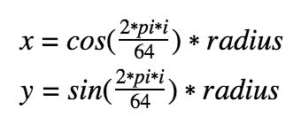
These coordinates act as a series of waypoints for the robot to move to with regard to its local coordinate frame, with the first waypoint being (R_bot, 0). The 3 motor controls are found at each waypoint by inputting the current desired direction vector (its x and y components are used for v_x and v_y) into the inversion of transform matrix described in the High Level Design section. The current desired direction vector is simply the current waypoint coordinate minus the previous waypoint coordinate. The output of this matrix multiplication are the three motor controls. The matrix multiplication follows a standard matrix multiplication practice in C with for loops. I found this webpage a helpful reference. These output values are raw and need to normalized and scaled to the max speed. This is done by dividing each output value by the max value at each index and then multiplying each normalized value by the max motor speed. Before converting these signed floats to unsigned integers for use with pwm commands, their signs are used to populate the motor direction arrays. If a control value is less than 1, the appropriate array index is set to 0, otherwise it’s set to 1. After all waypoints have been looped through, each motor has an array of pwm values and of binaries for motor direction. These arrays only need to be populated once per parameter entry set, so a conditional skips this thread after it is run the first time.
The second major software element is the ISR, which runs at 50 Hz off timer2. The ISR first checks that the motor control arrays have been populated, and then sets new motor control signals at a specified rate, which will be described below. To set new pwm signals for the dc motors, the ISR uses the SetDCOCxPWM(pwm_on_timex) command for motor x. To set GPIO pins for the motor drivers to set motor direction, the ISR uses the mPORTxSetBits(BIT_x) and mPORTxClearBits(BIT_x) commands for motor driver GPIO pin x based on the binary values in the motor direction arrays. The ISR sets pwm signals and GPIO pins for each waypoint and its corresponding motor controls, taking the SpiroBot through one circular lap. This is repeated for the specified number of laps, a parameter entry value.
The parameter entry section of the code is a jumping off point for future work, but for now the parameters are hard coded in. Spirographs, along with other interesting patterns, are made by controlling a number of parameters already mentioned, as described in the High Level Design section. Bot rotation rate, ω_bot, for the SpiroBot corresponds to the parameter input variable pause, which is the amount of time each set of motor controls is allowed to run before the ISR send the next set. Bot rotation radius, R_bot, is set via the variable max_speed. The higher the max_speed, the further the robot can move per ISR step, and hence the large its radius. The parameter variable for ω_base is w, which is the third input (angular velocity) in the transform matrix operation mentioned previously. Arm rotation rate, ω_arm, corresponds to the variable pwm_on_time4 and is set in the ISR via the SetDCOC4PWM(pwm_on_time4) command for the servo pwm signal. In this project, r_arm is manually adjustable but was not varied during testing.
Results for this project included countless hours spent fitting and adjusting the mechanical system, producing clean pwm signals, and checking variable types and values via an attachable TFT screen. Results also include some bad, interesting, and accurate drawings. A series of 6 official drawing runs produced an increasing level of quality to the SpiroBot. Below is a table with the parameter inputs for each run followed by a picture of the runs and video of the most successful runs.
| Run | pwm_on_time4 (3750-4250) | pwm4 period (s) | pause (ms) | T_bot:T_arm | max_speed (0-53750) | w or ω_base (rad/s) | Laps | Shape |
|---|---|---|---|---|---|---|---|---|
| 1 | 3875 | 3.4 | 47 | ~1.2:1 | 28000 | 0.0 | 10 | ovals |
| 2 | 3875 | 3.4 | 47 | ~1.2:1 | 28000 | 0.7 | 10 | triangles |
| 3 | 3900 | 3.0 | 58 | ~1:1 | 30000 | 0.7 | 10 | triangles |
| 4 | 3900 | 3.0 | 48 | ~1.2:1 | 30000 | 0.7 | 10 | triangles |
| 5 | 3950 | 2.0 | 38 | ~1:1.2 | 30000 | -0.7 | 10 | spirograph! |
| 6 | 3950 | 2.0 | 26 | ~1.2:1 | 35000 | -1.05 | 10 | spirograph! |
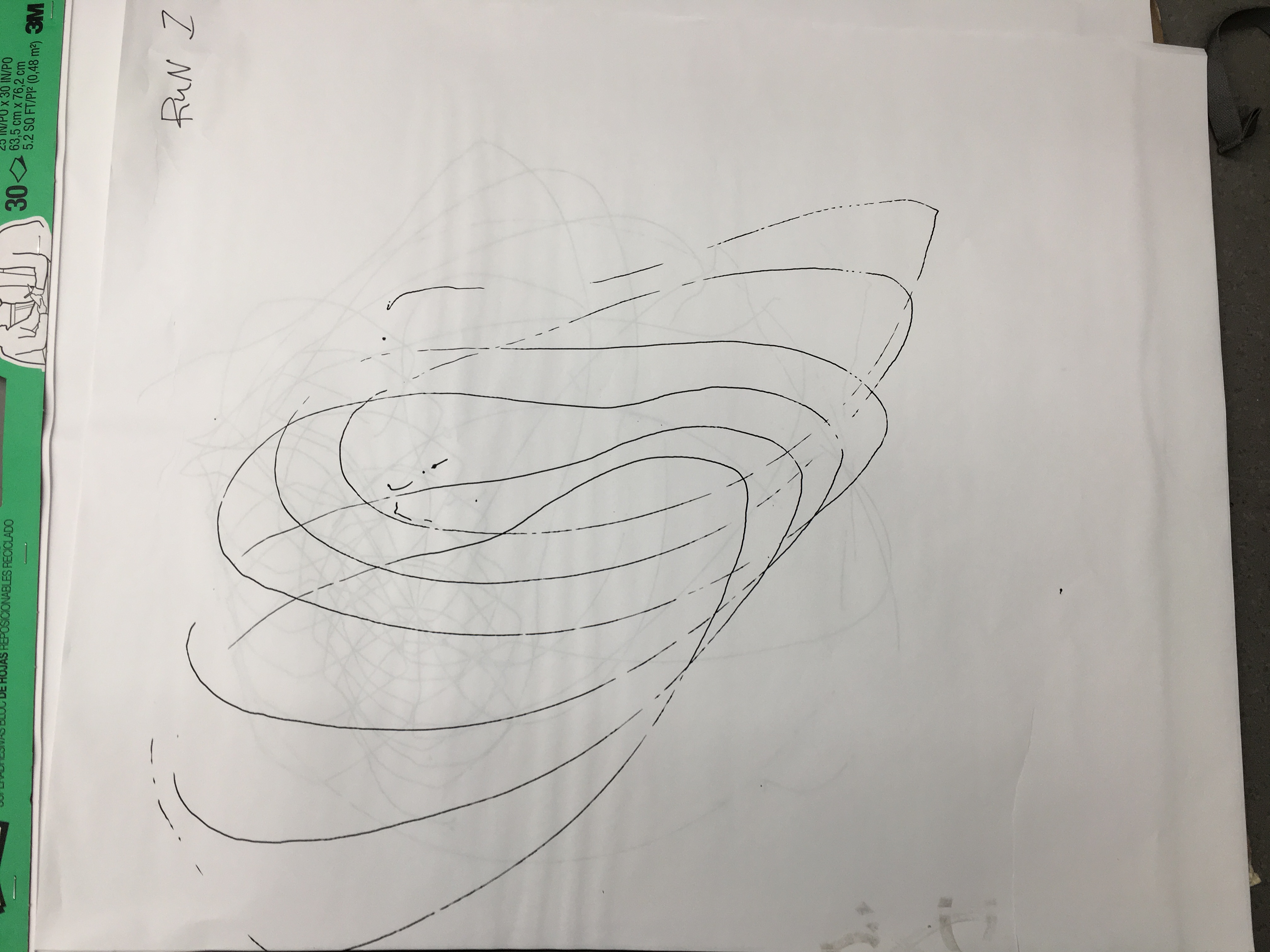
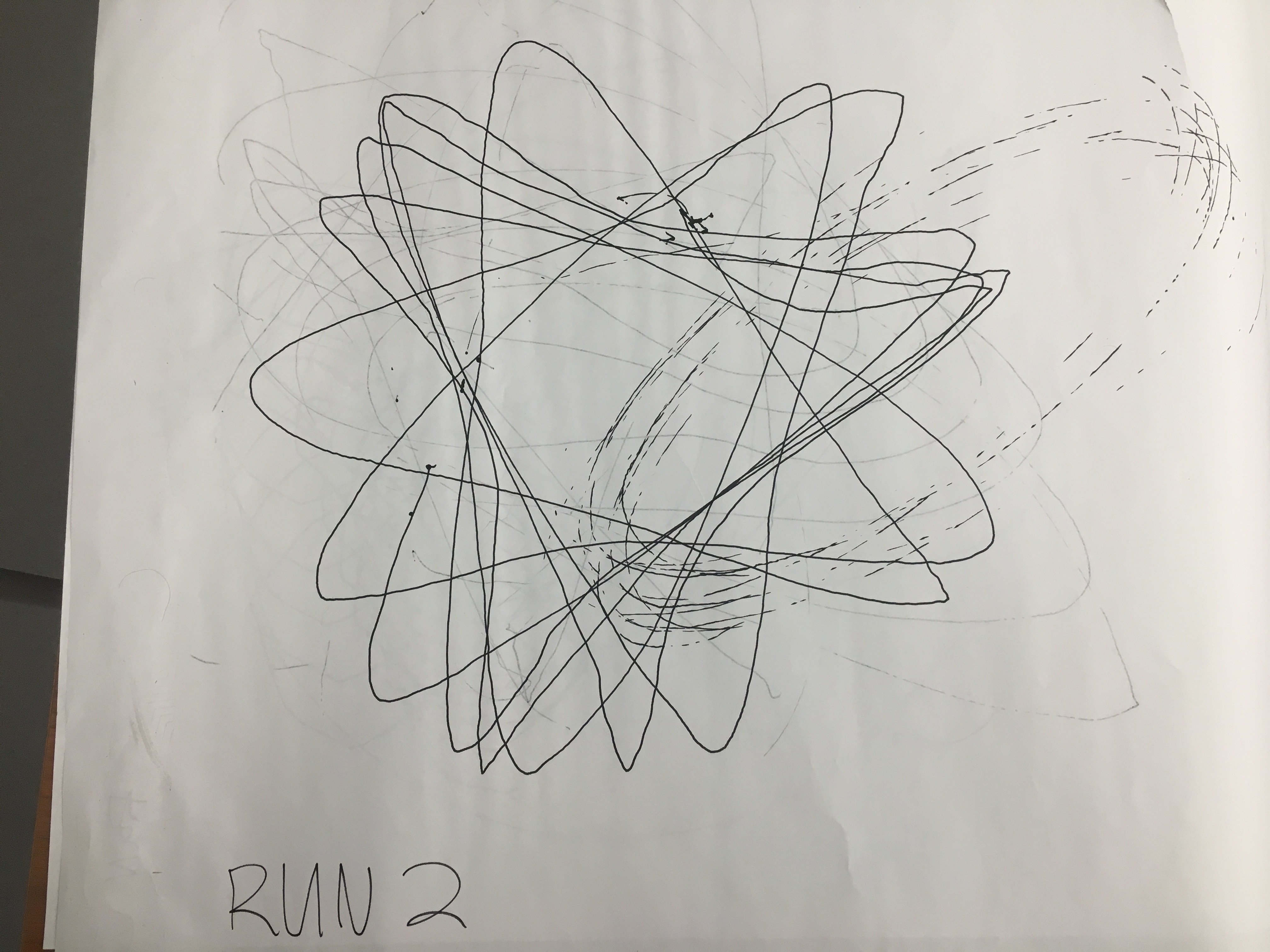
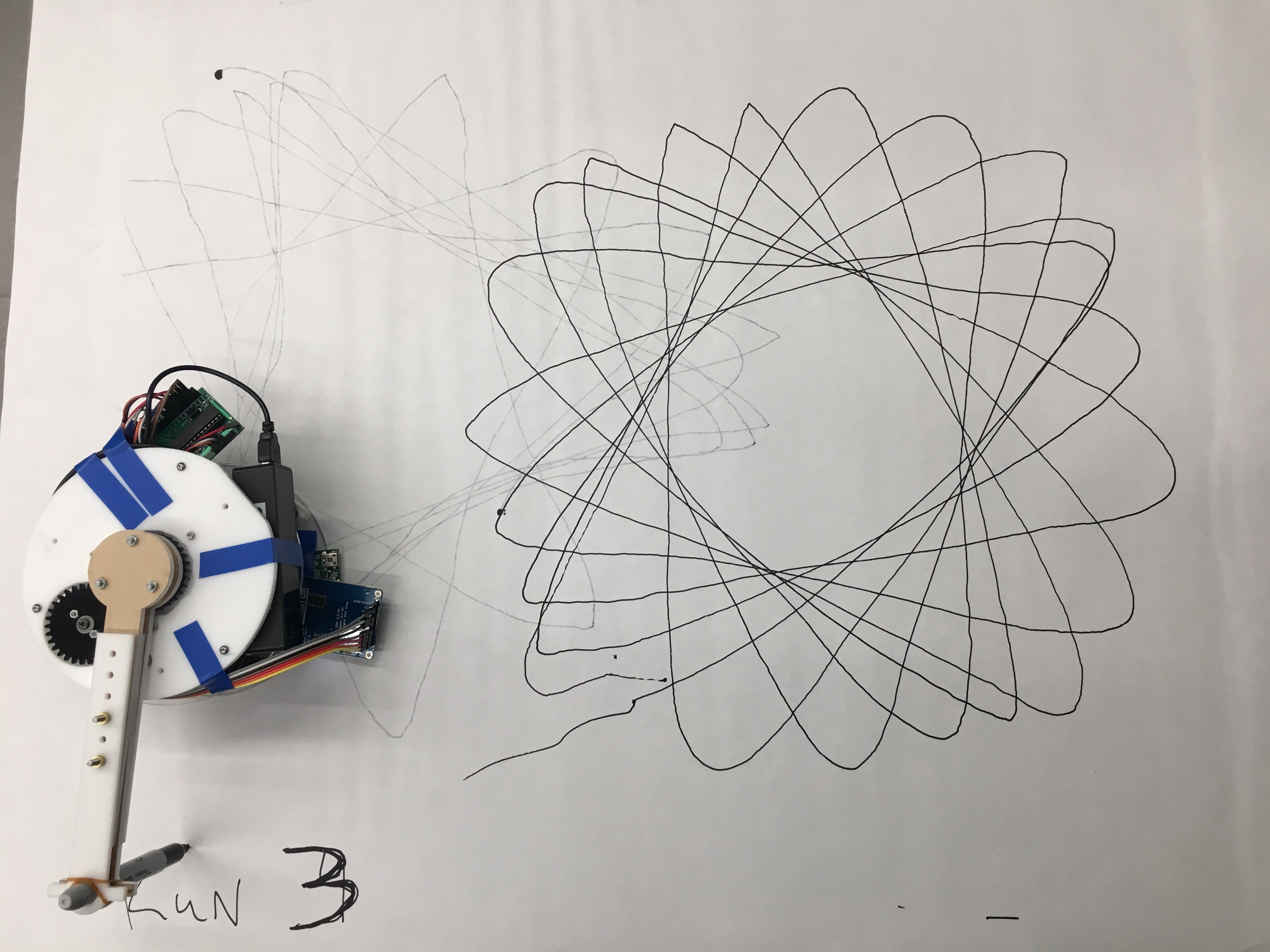
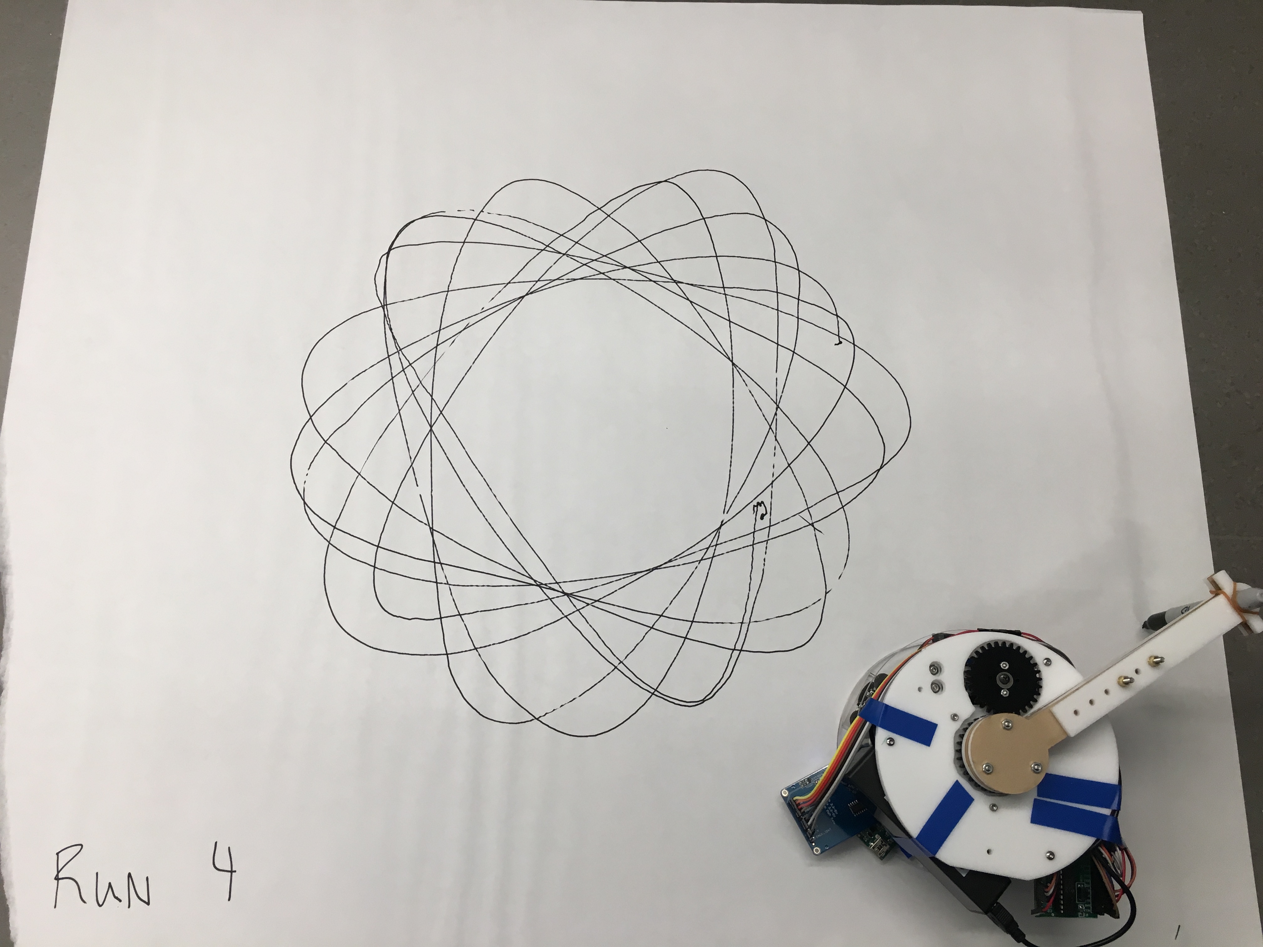
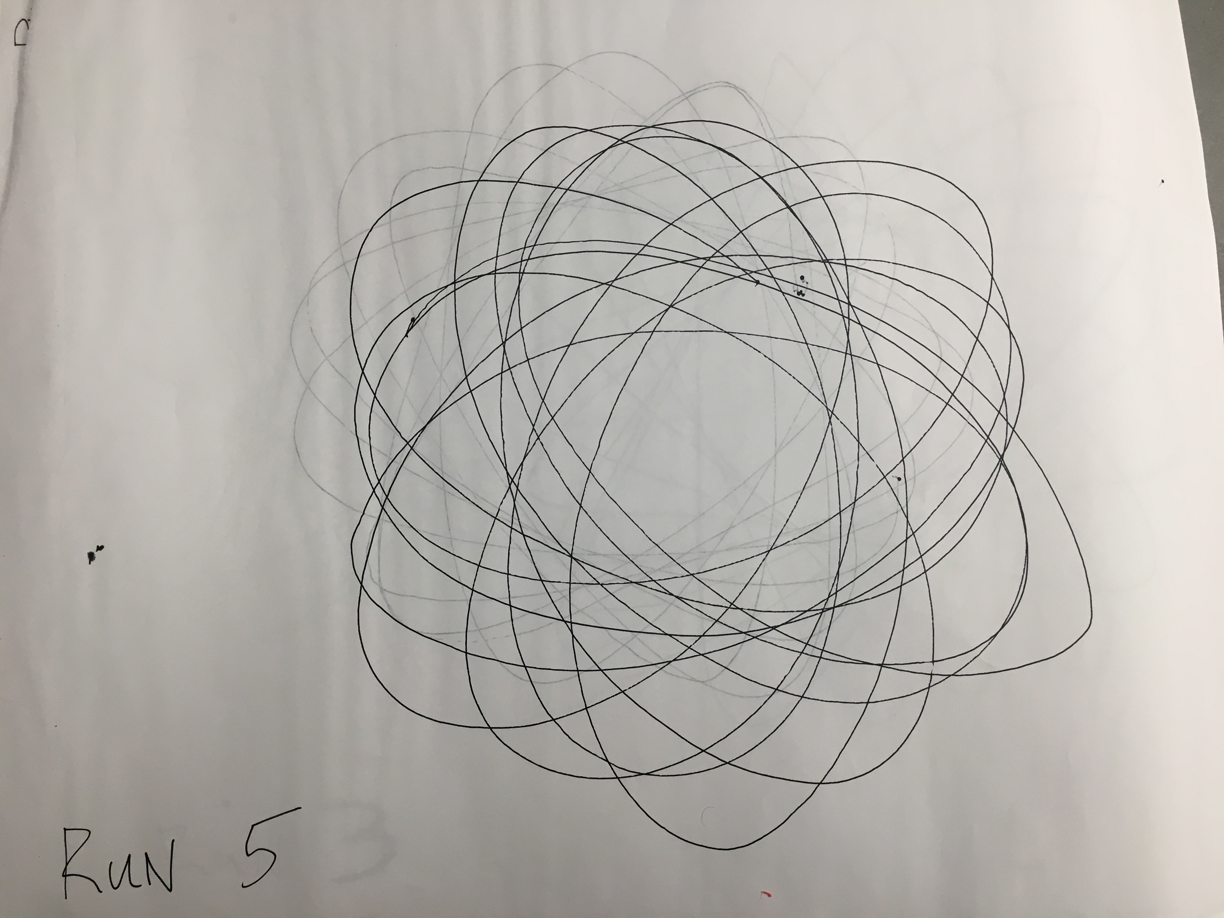
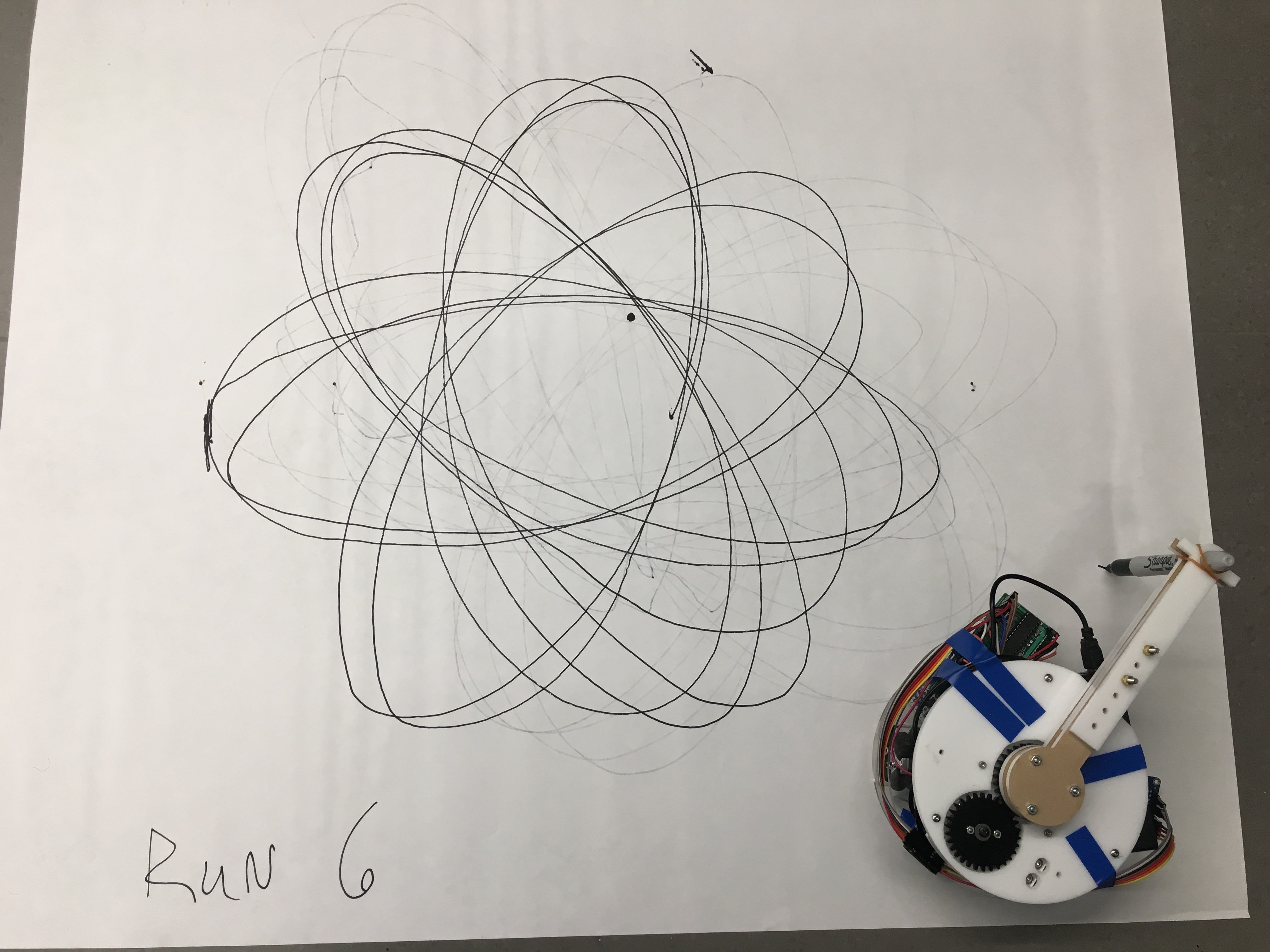
Run 3 was the most successful set of parameter values for a triangular pattern shape and run 6 was the most successful for a true spirograph pattern. The most important piece of information learned from these tests occurred during the transition from run 4 to run 5, when the robot base rotation direction ω_base was switched. The incorrect direction yielded an interesting pattern, nonetheless. The value for ω_arm was increased during testing to receive more consistent movement from the arm due to increased torque. Early on, the ratio between T_bot and T_arm (periods) and the value of ω_base were found to be important, and tweaked throughout testing. A ratio around 1:1 for T_bot:T_arm was found to achieve good results when mixed with ω_base rotation rates of significant value. T_arm was found using a stopwatch and T_bot was estimated by multiplying the pause value by 64, the number of steps per lap. Ultimately, a slight unbalance of this ratio allowed the SpiroBot to gradually increment its drawing pattern to find success. Increases in pwm_on_time4 corresponded to decreases in pause time, which necessitated an increase in max_speed to retain a decently sized R_bot. The pictures and videos show that the robot was able to repeat it’s path once it had drawn all of the elements of the pattern with decent accuracy. The faster ω_arm corresponded to smoother element tips (ie more curved and less pointy), a desirable quality of the drawing. In future work, interesting patterns may arise out of larger R_bot and r_arm values as well as a ratio around 2:1 for T_bot:T_arm.
This project was very intensive and very rewarding. The results were harder to come by than expected, but that’s always the case. I had hoped to reach some stretch goals, but accomplished much that I am proud of. I wanted to create a robust robot platform and accomplished that to my satisfaction, perhaps at the expense of more electrical development with the project. I would like to further develop this project and perhaps publish it someday. The next steps I would like to take are equipping the SpiroBot with bluetooth and connecting it with a phone for parameter entry. This entry can start as direct, but I would like to eventually fulfill my vision of transforming sound and music input into parameter values, and perhaps other drawing patterns and styles.
I considered ethics throughout this project, wanting to be truthful in my work and provide a quality product that might someday be used by others. Because of this, I didn’t try to oversell the abilities of the SpiroBot and tried to make it a robust and safe design for other users. I also tried to give as honest of credit as possible to reference material and resources that helped my project in any way. During this project, I was able to give and receive advice and ideas with a wide range of people, from engineers to people in Arts & Sciences to the elderly to children. The intent with this project has always been to improve the lives of those who use it in some way, and I hope that this feedback allows this robot to do that better. Specifically, I want people to see the wonderful capabilities of the future of technology and how it can enhance their enjoyment and creativity and learning, not just their productivity or ability to detach from reality. While receiving advice is important, it’s just as important to give it back. In this way, I spoke with a number of classmates about their projects and offered my honest and constructive advice, hoping to improve the outcome of their endeavors.
I approve this report for inclusion on the course website.
I approves the video for inclusion on the course youtube channel.
Commented code may be found here.
Schematic
Budget
| Item | Quantity | Cost | Total Part Cost | Vendor | Link |
|---|---|---|---|---|---|
| DC Motor | 3 | 15.95 | 47.85 | Pololu/Research Lab | DC Motor |
| DC Motor Driver | 3 | 3.49 | 10.47 | Pololu/Research Lab | Motor Driver |
| Omni Wheel | 3 | 6.40 | 19.20 | Ali Express/Research Lab | Omni Wheel |
| Bearing | 1 | 6.25 | 6.25 | McMaster | Bearing |
| Power Adaptor Cord | 1 | 3.96 | 3.96 | Amazon | Power Adaptor Cord |
| PIC32 | 1 | 5.00 | 5.00 | ECE Lab | |
| Microstick2 | 1 | 1.00 | 1.00 | ECE Lab | |
| Small Board | 1 | 4.00 | 4.00 | ECE Lab | |
| Continuous Servo | 1 | 11.95 | 11.95 | Adafruit/Research Lab | Servo |
| Power Bank | 1 | 0.82 | 0.82 | Amazon | Power Bank |
| 9V Battery | 1 | Research Lab | |||
| Sharpie | 1 | Research Lab | |||
| Nuts and Bolts | Research Lab | ||||
| Tape | Research Lab | ||||
| Connecting Wires | Research Lab | ||||
| Protoboard | 1 | Research Lab | |||
| Acrylic | Research Lab | ||||
| Rubber Band | 1 | Research Lab | |||
| 3D Printed Parts | Research Lab | ||||
| Paper Canvas | Research Lab | ||||
| Total Cost | 110.5 |
This was a one-man operation so I did everything for the project.
References have been linked throughout the webpage. In addition to these, the course website and its many help pages and links were incredibly useful. The following webpages were also helpful.
Servo Datasheet HTML Basics Wheels