Hardware Components
Below is a list of all the necessary hardware parts to build this project:
1. PIC32 microcontroller x 1
2. SN754410 Quadruple Half-H Drivers x 1
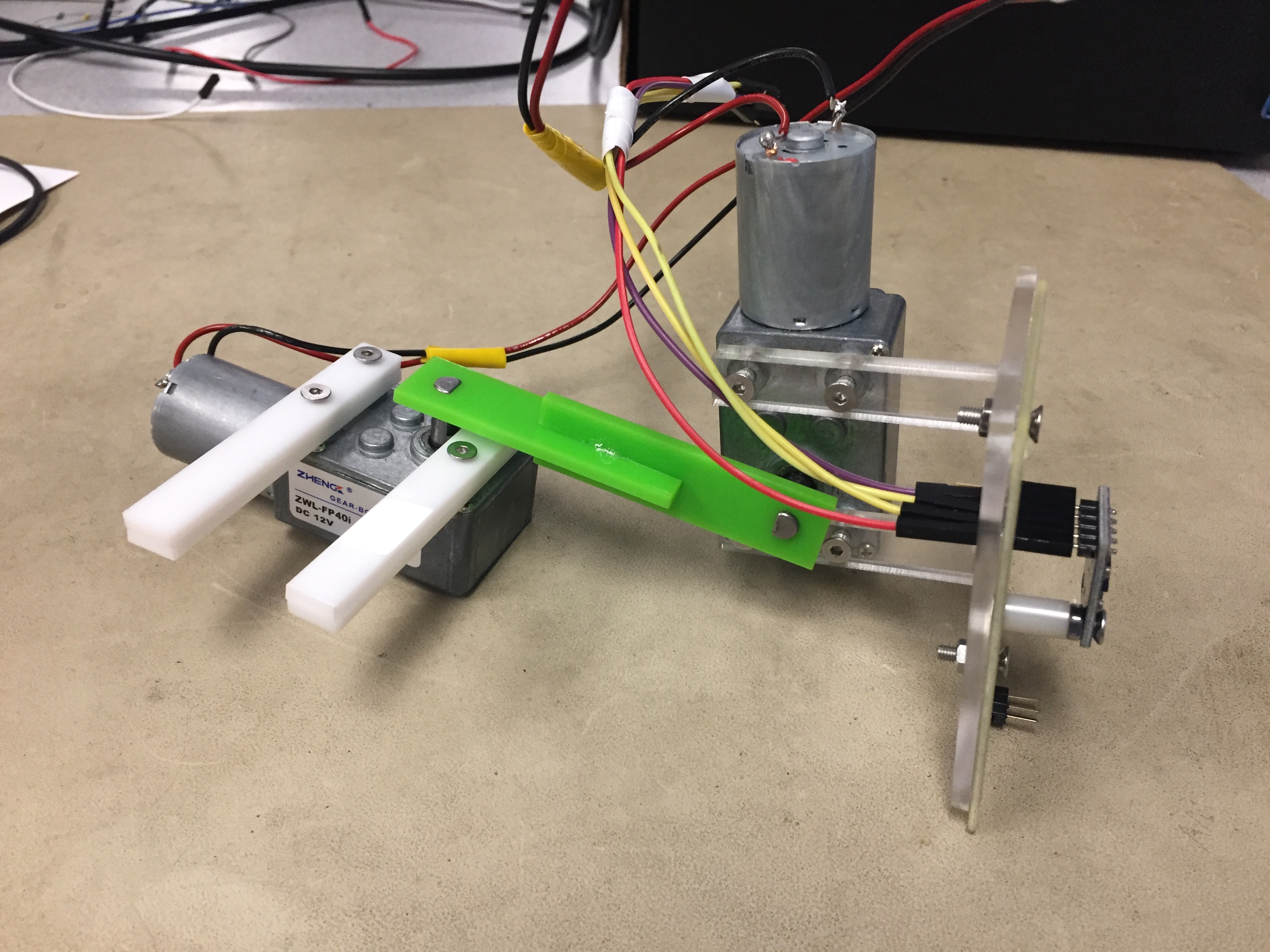
3. uxcell DC 12V 200RPM 6mm Shaft High Torque Turbine Worm Geared Motor x 2
4. GY-61 Accelerometer x 1
Besides, you also need some laser cut, 3-D printed materials to setup the frameworks, and some resistors, capacitors, and wires to complete the circuit.
Schematics
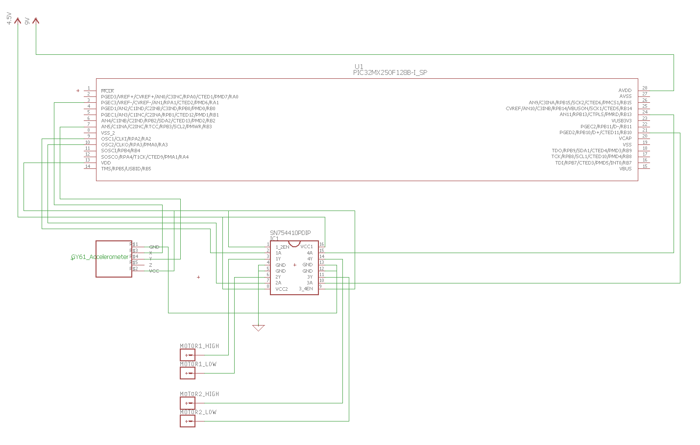
Figure 1
The schematic in figure 1 shows how pins are connected. Pin 9, 10, 21 and 24 on the microcontroller are used to control two motors, and are passing into the 4 control pins of the H-bridge, 2 for each motors. Pin 3 reads output value of x-axis and pin 7 reads value of y-axis from the accelerometer. The enable bits for H-bridge are always set. The motors are powered by a 4.5V DC power supply, and the microcontroller is powered by a 9V DC power supply. The accelerometer is powered by a 3.3V voltage coming out from the microcontroller.
Mechanics
When there is an error angle along the x-axis, as illustrated in the following graph,
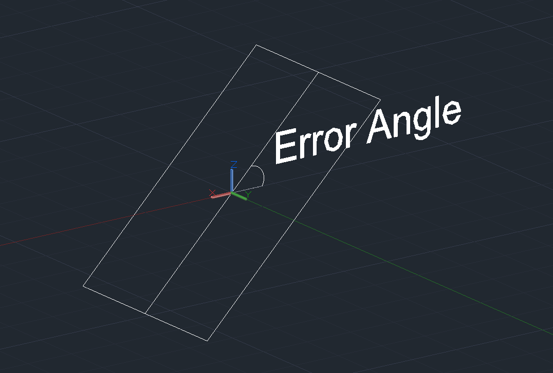
Figure 2: Error Angle in X
we need to activate the motor in x-axis to rotate clockwise, as illustrated in the following graph:
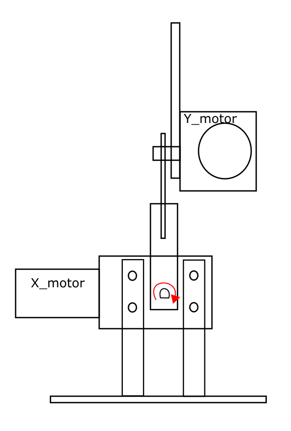
Figure 3:Front View
When there is an error angle along the y-axis, as illustrated in the following graph,
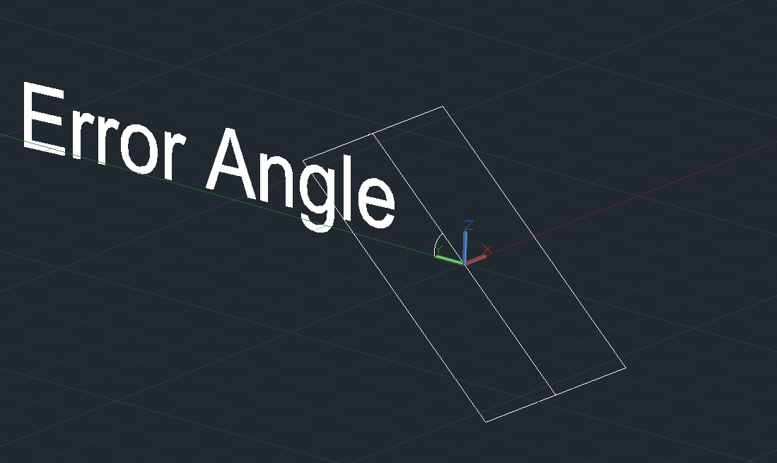
Figure 4: Error Angle in Y
we need to activate the motor in y-axis to rotate clockwise, as illustrated in the following graph:
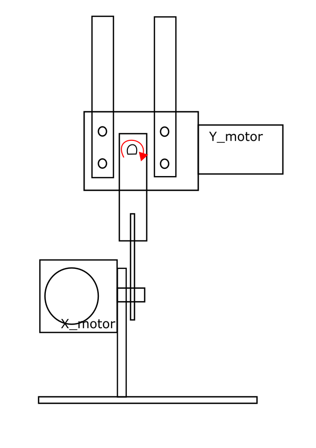
Figure 5: Side View
When there are error angles in both x-axis and y-axis, we just need to activate both motors, and each will try to overcome the error angle in its own direction.
Software Design
Accelerometer Values Read
We used the code adapted from ADC_setup_two_chan.c to read ADC values using two channels.
One problem in reading ADC values is that, the accelerometer is very sensitive, so a tiny force would cause a spike in the read, shown in figure 6. This sensitiveness would cause the system highly unstable. When the motor starts to rotate, it gives the accelerometer a force which causes a spike. When being held by hand, the unsteadiness from hand causes spike, too. The spikes make the system to think the plane is rotating back and forth rapidly with large amplitude, so the motors will respond according to the spikes, causing severe jitter. To resolve this issue, we implement a temporal average filter which takes the average values of last x consecutive read values as the input signal. This feature wipes out the effects from spikes and stabilizes the system. The possible drawback of the filter is that the system is less sensitive to a real displacement. However, we are running the measuring thread with a very high frequency, so the system can still respond in a short time.
We have also tried to use a counter to filter out the noise, but it turns out the counter filter performs worse than a temporal average filter.
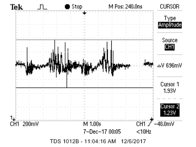
Figure 6
Motor Driver
We implement a simple motor driver code to control motors. Because we are using a H-bridge to control the rotating direction of motors, we need to set and clear bits for six pins, which consist of two enable pins and four control pins. Wrapping the control detail in a driver makes the code clean and readable.
Control Thread
We uses ProtoThread to implement our control thread. The thread reads in two ADC values, filters the signal using a temporal average filter, and set the motor control signals accordingly. It compares the filtered values with the pre-set values (illustrated here). If they are different, the thread will set the control signals of motors to rotate the plane back to horizontal state.
A threshold value is set to tolerate a certain range of error because the accelerometer is sensitive and it is nearly impossible to keep the gimbal's head absolutely horizontal. The threshold value is chosen such that the machine will not jitter at steady point and the plane is still kept horizontal in human's perspective.
The thread runs at 20Hz, so the response time of gimbal should be 50 milliseconds. Because we use a temporal average filter which averages last three consecutive read values, the estimated response time should be within 50ms - 150ms.
Calibration
The only input device in our project is a accelerometer GY-61 ADXL335 which can read acceleration in X, Y, Z direction. Because in our project we have two motors to balance the head, so we only use read values from x and y axes. When Vcc and GND is connected, the output values from pin x_out and pin y_out is within the range of 1.26V to 1.89V, with center value at 1.5V, as shown by figure 7.
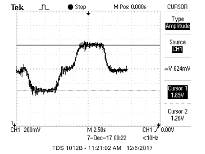
Figure 7
We use on-board ADC to read in the voltage outputs from the accelerometer. The read value of ADC ranges from 0 to 1023 but in this project the read values are from 400 to 600 because of the limited range of voltage outputs from GY-61. It is sensitive and precise enough in our case.
To calibrate, we keep the accelerometer horizontal and record the read values, which are used to represent horizontal state. The calibrated value is 492 for X axis and 496 for Y.
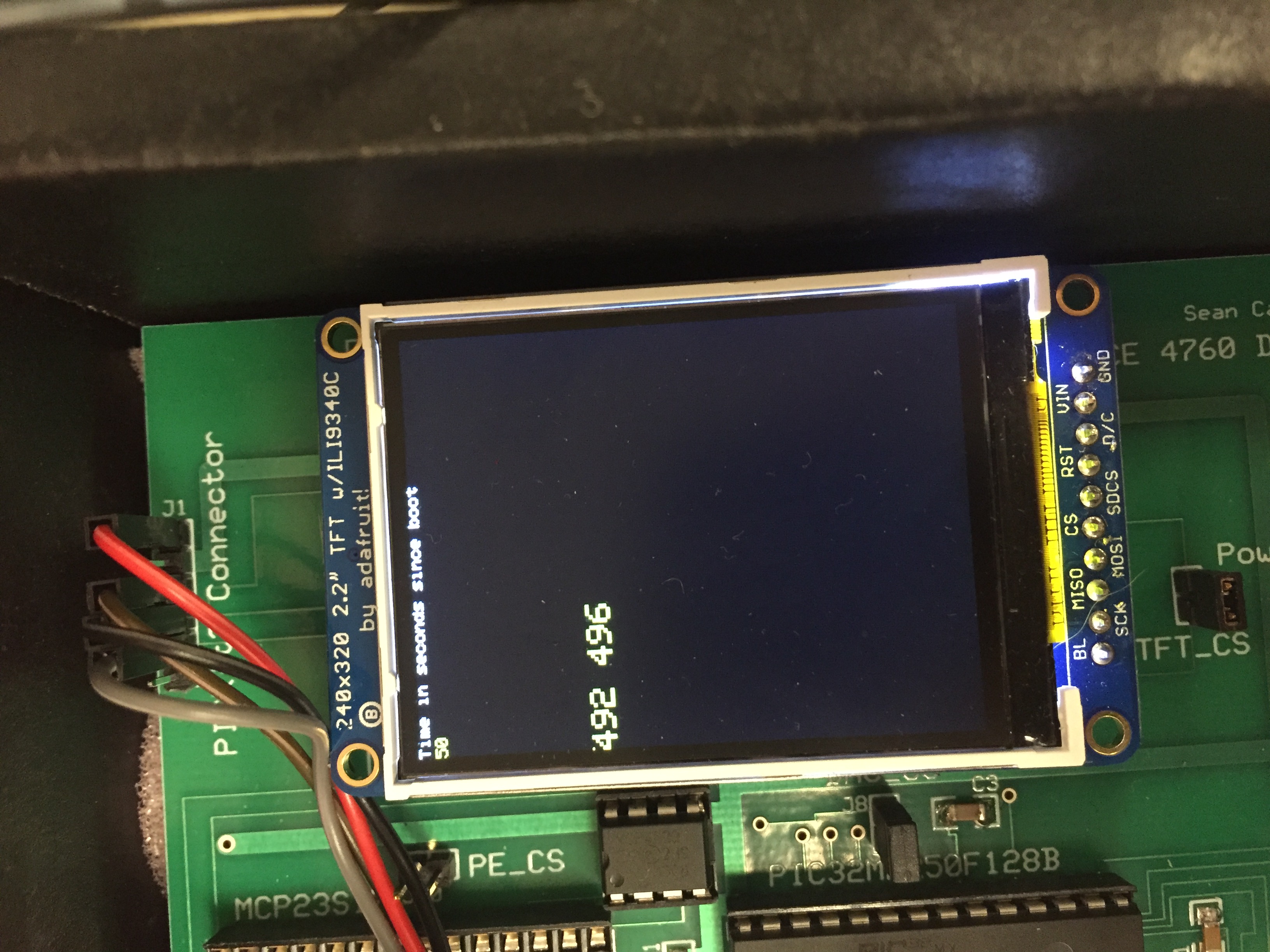
Figure 8
Demo Video
Response Time
The actual set time is hard to measure because moving the handle takes time and the gimbal will start calibrating the head as soon as the handle starts moving. Theoretically, the response time is around
100ms. By observation, the calibration happens in real-time.
Accuracy
In general
Our two-axes gimbal can keep the head horizontal as expected. When the handle is moved or rotated, the motors will rotate in the head (plane) in X- and Y-axis to keep it horizontal. In most of the cases, the head can go back to horizontal state in a short time. As shown in figure 9, at first the plane stays horizontal, and then the handle is moved. The read value goes back to the original value after a short time, indicating the plane moves back to horizontal state.
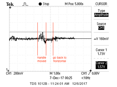
Figure 9
Jitter
Some times the head will jitter after going back to horizontal place. Figure 2 shows the accelerometer read value in this situation.
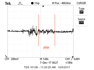
Figure 10
We discussed with professor and camp up with several possible reasons:
1. Our hand is not steady: we cannot keep our hand perfectly steady, so it is possible that our hand cause the ADC read value to fluctuate around the threshold value, and the gimbal is balancing itself intermittently. However, because we are using a temporal average number to filter out the noise (mentioned in software design), this case is unlikely.
2. Motors are glitched. The motors we use are gear motors. Because we have applied torque that is larger than the maximum allowed value on the motors, it is possible that the gears are damaged. We have observed that jitter only happens on the motor rotating in Y-axis and only happens when the motor rotates anti-clockwise. Therefore, it is very likely that the jitter is caused by mechanical issue.
Overshoot
Besides the jitter, it is observed that sometimes the head will overshoot, which is shown by the figure 11. In the example the overshoot value is 96mV, corresponding to around 30 degrees, which is not a negligible quantity.
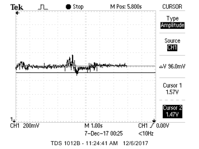
Figure 11
There are three possible reasons.
1. Our frequency of reading ADC values is not high enough, so the motors do not stop when it reaches the horizontal state because the read value is still the old value. However this case is unlikely because our yield time for the thread is only 50 millisecond, fast enough in our case.
2. The motors are rotating so fast that it is possible to overshoot the threshold range in 50 millisecond. To test this hypothesis, we modified our code and let motors rotate for only 50 milliseconds. By reading the difference in ADC output we conclude that this is not the reason in our case.
3. we used a temporal average filter to filter out the noise. The drawback brought by the filter is that when the plane reaches the horizontal state, the filtered read value from ADC is still off the steady value, because we are taking the average of last three consecutive read values. Therefore, the motors will go a little bit further and go back. If the overshoot is not cause by mechanical issues, this is the most possible reason. The possible improvement will be discussed in conclusion section.
Our project works out as expected. The plane can be kept in horizontal state and the set time is within 1s. The error is also small.
However, since it's a plan B project (for our plan A, see Anecdote), it is simple, and can be improved much more.
Further Thoughts
Real Gimbal!
It is a good idea to add in another motor, which can rotate the plan in horizontal direction. With this extra motor, the plane can be made to point at a fixed angle, and the project would be more like a real gimbal.
PID Control
If PID control algorithm is adopted in this project, the control on motors would be more smooth. It is obvious that the overshoot mentioned in result section can be resolved via PID control algorithm.
Intellectual Property Considerations
The project is not difficult and we believe there should not by any intellectual property considerations. We use the code from ADC_setup_two_chan.c, and we put the file in reference list
Ethical Concerns
This project does not endanger the public or the environment, and we believe our project does not have interests conflict with any party. Although it's a gimbal, it is simple and cannot compete with existing commercial products. However, the concepts we used in this project are helpful in understanding how to achieve a stable system. The concepts are widely used in current intelligent systems.
Our data and measurements are all real, all of which can be found in code or figures. If anyone has any doubt on our measured data, feel free to contact us. We are happy to share our experience on how the data can be collected. When building our projects, we discussed with each other, and with professor and TAs. We listened to other's advices carefully because they are very helpful, but we would also think thoroughly before we take any advice. To protect intellectual property, we strictly follow reference rules and list our sources in the appendix. We are confident that the code we used in this project does not violate any intellectual property.
We pay attention to others' safety, as well as their property, reputation. Therefore, we follow safety rules when constructing and tuning our system.
Appendix A
The group approves this report for inclusion on the course website.
The group approves the video for inclusion on the course youtube channel.
Appendix B: Part List
- MicroStickII $1
- Big Board $10
- White board $6
- PIC32MX250F128B $5
- TFT LCD $10
- Two uxcell DC 12V 200RPM 6mm Shaft High Torque Turbine Worm Geared Motor 13.32x2 = $27
- GY-61 acceleromter $5
- SN754410 H-bridge $12
- Socket for H-bridge 16x0.05 = $0.8
- Jumper cable $2
Appendix C: Reference
Datasheet: PIC32MX250F128B
Setup Two ADC Channels
Appendix D: Schematics
Schematics
Appendix E: Work Distribution
Yang Liu
Motor Driver
Basic Control Logic
Circuit Assembly
Yangyi Hao
Mechanical Construction
Control Logic Optimization
Circuit Assembly
Appendix F: Vendor Site
uxcell DC 12V 200RPM 6mm Shaft High Torque Turbine Worm Geared Motor
Adafruit
Appendix G: Commented Code
Gimbal.X.zip
Brief "History"
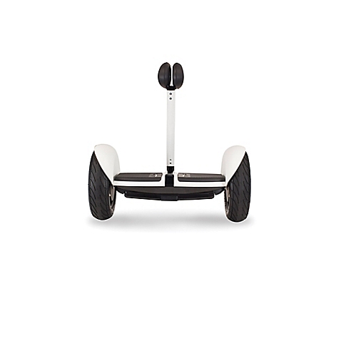
In the beginning, we wanted to build a segway for the project.
What we aimed to accomplish was:
Imagine
And we constructed out alpha verision without much consideration:
Alpha Version
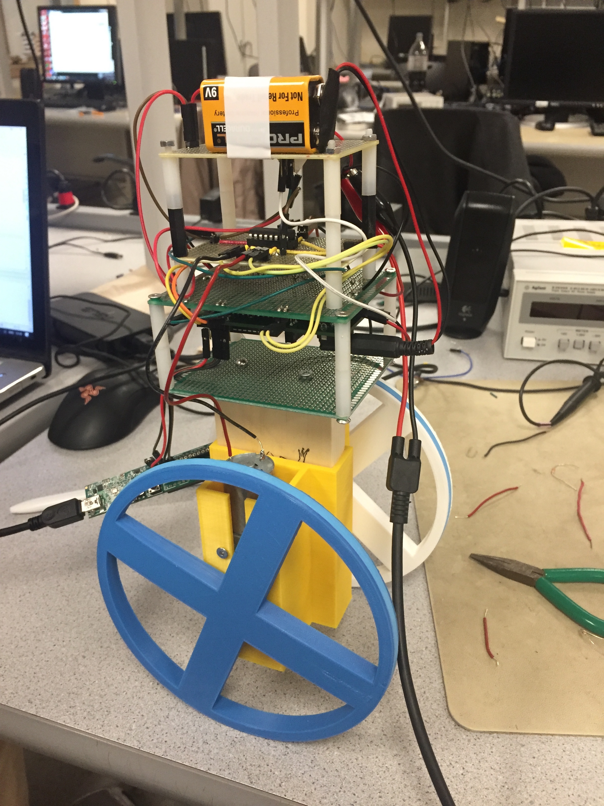
However, the model was short so the moment of inertia was small, which made it extremely hard to keep it balanced. The wheels were too big as well, so the torque applied to motors was so large that the motors could not rotate. Therefore, we improved our design and constructed our beta verison.
Beta Version
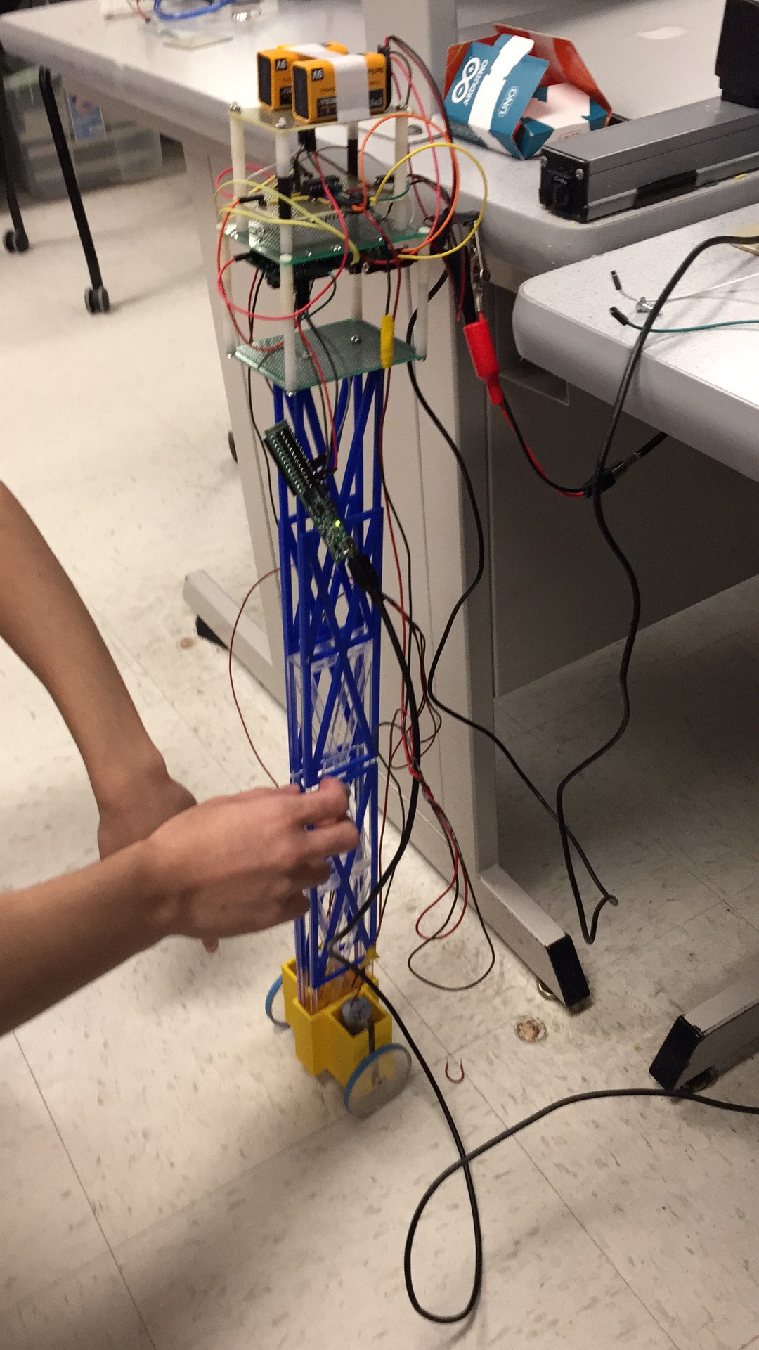
The beta version was much more similar to a real segway. The moment of inertia was big and radius of wheels were short. After two-day's tuning, we failed to keep it balanced. It was ten hours before demo but we still had nothing. So we decided to take what we have and build a working project for demo. Better than nothing. As a result, our segway became a gimbal. We call it the legacy of a segway.
Product