Anant Desai (ahd76)
Jeremy Storey (jks284)
Project
- VR Sword Defense Video Game
https://www.youtube.com/watch?v=TVv_XRQA7QU&t=
Introduction
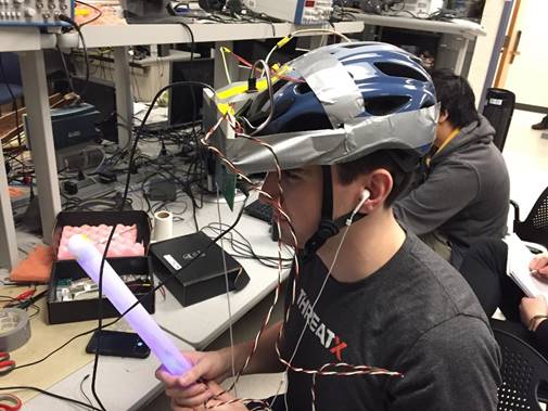
In this project, we constructed a virtual
reality (VR) video game. The video game uses several peripherals to give the
user an immersive gaming experience. This includes providing visual, auditory,
and tactile feedback from the game. The game features a headpiece with a TFT
display. The display shows incoming projectiles that the player must
deflect/eliminate with a sword. Upon impact, the player receives an unpleasant
sound through the earpiece and tactile feedback via the vibration motors in the
headpiece. A magnetometer at the top of the headpiece causes the screen to
change based on the direction the player is facing. The objective of the game
is to survive as long as possible. The goal of the
project is to provide an enjoyable yet safe immersive gaming experience.
High Level Design
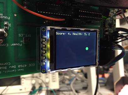
In the game, the user wears a headpiece with a
TFT display on it. This TFT displays projectiles (balls) that are moving
towards the player. There can be a projectile incoming on the left or the right
of the screen. Additionally, the TFT displays the player’s score and health.
The score is how long in seconds that the user has survived the game. The
health begins at 5 and decrements every time the user gets “hit” by one of the
balls. When the health reaches 0, the game terminates. There is a game reset
button which allows the player to continue with another round of the game.
The headpiece features a magnetometer, which
determines which way the headpiece is pointing. Based on this, the screen that
the TFT is displaying will change. This gives the impression to the player that
the game’s screen changes based on the direction that the player is facing.
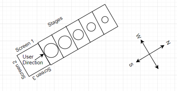
This is a pivotal part of the immersive experience. In total, there are 4
possible screens. The figure below illustrates what the virtual environment
looks like for one ball. The “stages” are meant to illustrate the ball
increasing in size as it gets closer to the user. Screens 1-3 illustrate
different screens the user is not currently looking at.
To combat the incoming projectiles, the player
is armed with a sword. The sword contains accelerometers at its tip to detect
when the sword has been swung and when the player is swinging the sword
left/right. When the ball is close enough, the player must swing the sword in
the correct direction to deflect/eliminate the incoming projectile.
If the player gets hit by a ball, there is
auditory and tactile feedback. The auditory feedback consists of a sharp,
slightly distasteful, sound to indicate to the user that he or she has been
hit. To allow for tactile feedback, the headpiece has vibration motors placed
on the light, right and back side. When the user gets hit from the left, right,
or back, then the appropriate vibration motor will vibrate. If the user gets
hit from the front, all three vibration motors will vibrate.
There were hardware software tradeoffs in the
form of adding hardware complexity tended to add software complexity. In
general, changing hardware created more software work, whereas software changes
didn’t change much of the hardware.
This project was the result of brainstorming
between the group members with the goal of creating a game that involved swinging
a physical sword to control a video game.
Program/Hardware
Design
Hardware Description:
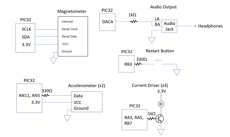
A full hardware schematic is available in
Appendix B. For the following, refer to the schematic to find the specific
“port pins” being mentioned.
The first piece of hardware to be constructed
was the sword. Two 1-dimensional accelerometers were soldered together at a 90 degree angle to essentially create a 2-dimensional
accelerometer, capable of noting the general direction of a sword swing. These
accelerometers were placed in the tip of a recycled, light up, plastic sword
with wires from the accelerometers coming out of the handle of the sword. The
accelerometers provided values between 0 and 3.3V, corresponding to the force
being applied to the accelerometer. As such they were connected to the ADC
inputs of the PIC32 for interpretation via 330Ω resistors.
The PIC32 port pins could not supply the
required 70mA of current to power the three vibration motors. A simple current
driver was constructed using three 2N3904 transistors with the collector
connected to power via a vibration motor. The base was connected to one of the
port pins of the PIC32 via a 1kΩ resistor. This pin was internally pulled down, and pulled high when the program told the motor to
vibrate.
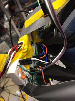
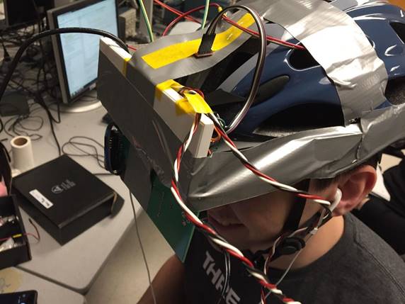
The vibration motors were placed in the helmet
to provide the user tactile feedback when being hit by a ball. There were three
motors in total: left, back, and right. Being hit from the front triggered a
special condition. The screen and circuitry for the rest of the device were
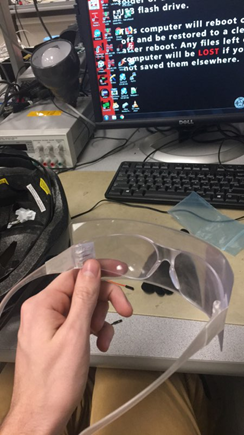
attached to the visor of the helmet. The screen was quite close to the users
face when wearing the helmet, so a Fresnel lens was attached to the front of a
pair of safety glasses to help the user focus on the screen.
The simplest part of the schematic was the
restart button. This was a push button connected to ground on one side and a
PIC32 port pin via a 330Ω resistor. This pin was internally pulled high.
The restart button is meant to signal the software to restart the game when
pushed after the game has ended.
The audio output circuit takes the audio signal
from the DAC, passes it through a low-pass filter, puts it into an audio jack,
and outputs the sound to an external speaker. The audio jack’s left and right
audio pins are tied together since there was no differentiation between left
and right audio. Since the design only required a short sound upon being hit,
an audio filter to increase the quality of sound was not constructed.
Software Description:
The software design consists of 5 protothreads,
1 interrupt service routine, 2 helper functions for I2C, and 1 main function.
First, we will describe the main function and all the peripherals it sets up
along with the variables it initializes. Then we will discuss the purpose of
the interrupt service routine and the need for it. Lastly, we will go through
the 5 protothreads, describe each one’s functions, and how they intertwine.
When describing the communication over I2C with the magnetometer in one of the
protothreads, we will describe the read and write I2C functions in detail.
The main function first sets up timers 2 and 3.
Timer 2 is set with a period of 400000 so that it completes 100 cycles every
second. Timer 3 is set with a period of 909 so that it runs at a rate of 44
KHz. Timer 2 is then set up to be used to trigger an interrupt, while Timer 3
is used to initiate DMA transfer for audio. Then, the main function sets up the
SPI channel so that the PIC32 can send data to the DAC in order to produce
sound. Next, the I2C channel is set up and I2C1 is enabled. Along with this, we
write certain control bits in the magnetometer to bring the magnetometer to
active mode from standby mode so that its registers can be read. Next, the ADC
is initialized with auto alternate mode, which allows the two specified analog
input channels to be read in an alternate fashion via subsequent calls of the
ReadADC10 function. Then, certain pins are designated as digital outputs for
controlling the vibration motor current drivers. The DMA channel is initialized
with Timer 3. The protothreads and TFT are then initialized and system wide
interrupts are enabled. The variables for the game (health, score, restart) and
the valid bits for the all the screen are initialized to appropriate values
before the game commences. Then the 5 protothreads are scheduled round robin.
The interrupt service routine, which executes at
100 Hz, is used to read and process analogy inputs from the accelerometers on
the sword. First the ISR checks if the previous sword swing has been processed.
If not, then the ISR just ends. Otherwise, we are accepting new sword input. In
this case, we read from the ADC to obtain the value for the vertical and
horizontal accelerometers. If the vertical accelerometer’s value indicates that
the sword is swinging downward, then the horizontal accelerometer value is checked and we determine if the sword is swinging left or
right. Then, the accept_sword_input variable is set
to false so that the next time the ISR occurs we will not accept further sword
input until the current swing is processed. We need to use an ISR to read sword
input rather than simply reading it during a thread because the time scale of
the accelerometer is too fast to be read by a msec
timed thread.
Next we will describe the five protothreads: change screen, display
screen, update screen, sword, and sec. The first protothread, change screen,
reads from the magnetometer using i2c read. The i2c read function is modeled
off of the i2c read function from the Blimp-F-O project (http://people.ece.cornell.edu/land/courses/ece4760/FinalProjects/f2015/bjr96_jl2628/bjr96_jl2628/bjr96_jl2628/index.html). The i2c read function starts an I2C transaction by transmitting
the start bit. Then the i2c read function write the slave address of the
magnetometer for writing followed by the register to read from. Then the i2c
read function restarts the i2c transaction and then it writes the slave address
of the magnetometer for reading. Then the i2c read function reads the register
and does not acknowledge the result to end the transaction. Based on the values
read from the magnetometer, the change screen thread determines if the current
screen should change. If it should, then the current thread is cleared. Lastly,
the change screen thread displays the player’s stats, such as health and score.
The next protothread is the display screen
thread. The display screen thread simply checks if the left and right sides of
the current screen are valid (i.e. if they have a projectile that should be
displayed). If is is valid,
then this thread draws the projectile onto the screen.
The next protothread is the update screen
thread. The update screen thread iterates through all of
the screens and checks if any of the projectiles have hit the player. If one of
the projectiles has hit the player, then that projectile is eliminated off of its respective screen. The health counter is then
decremented. Furthermore, the DMA transfer for the hit sound is initiated. Lastly,
the appropriate vibration motor is turned on. For example, if the ball that hit
the player is on the screen that is behind where the player is currently
looking, then the vibration motor on the rear of the helmet will vibrate. If
the user was hit from the left, the left vibration motor will vibrate. If the
user is hit from the front, all three motors vibrate. After a quarter of a
second, all vibration motors are turned off.
The next protothread is the sword thread. The
sword thread uses the variables set by the ISR to handle the sword event.
Specifically, if there was a left sword swing detected and there is a valid
projectile on the left of the current screen, then that projectile is marked as
invalid and disappears off the screen. The same is true for the right sword
swing and a projectile on the right side of the screen. Once the sword input is
processed, the accept_sword_input variable is marked
as true so that the ISR can process further accelerometer input.
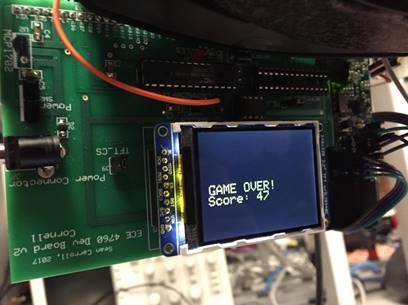
The last protothread is the sec thread. This
thread keeps a running count of the number of seconds that the game has been
active. These number of seconds also correspond to the score of the player. If
the player’s health hits 0, then this thread clears the screen, displays “GAME
OVER” with the score, and then waits in a while loop for the restart button to
be pressed. If the restart button is pressed, then the game variables are
reinitialized. This means that all screens are marked as invalid (i.e. there are
no valid projectiles on any screen), the health is reinstated at 5, and the
score begins again at 0. The screen is then cleared for a new game.
Results
Because this was a video game, a lot of the
testing dealt with user experience. This meant that if the game looked like it
was functioning correctly, then it was functioning correctly. The major aspects
of this testing dealt with making sure we were reading from the accelerometers
fast enough to capture the sword motions and to make sure we were reading from
the magnetometer fast enough to enable smooth transitions of the screen.
Lastly, we needed to ensure the important protothreads were getting enough CPU
time to render the game and make the visuals look believable. We describe these
three aspects of testing further.
First, we worked with the accelerometers.
Because of the small time scale of the sensor output
when the accelerometer was perturbed about an inertial state, we needed to
embed the ADC reading in an interrupt service routine. After slight
experimenting with the frequency of the ISR, we determined that 100 Hz was sufficient to capture the behavior of the accelerometer.
Having the ISR frequency be lower than this would have resulted in missing information, but having it much higher would cause
unnecessary CPU time wasted when the ISR is triggered unnecessarily often. For
the accelerometer, when the sensor accelerates in one direction, we see a spike
in the output voltage, but when the sensor slows down (decelerates), there is
an equivalent negative spike in voltage. It was important to sample fast enough
to ensure we were able to capture the first spike so that we could accurately
determine the direction of the sword motion.
Next, we worked with the magnetometer. The magnetometer
didn’t need to be read as frequently as the accelerometer. This is because we
only needed to read the magnetometer as often as we wanted to allow the screen
to change. This meant that we could put the code that read from the
magnetometer via I2C in the protothread that was in charge of
changing which screen the user was viewing. This allowed us to couple the
magnetometer reading and the rate of screen change, since these two values
should match up. Specifically, it does not do us any good if we read from the
magnetometer more often than we are updating which screen the user is looking
at. Additionally, we seemed to be getting a significant amount of magnetic
interference from the room as the magnetometer was somewhat unreliable at
higher degrees of resolution.
Lastly, we needed to ensure the protothreads
weren’t yielding for too long and that the game rendering had minimal flicker
and glitches. The first place to check was the protothread that actually printed the projectiles on the screen. This thread
had to execute often enough that the motion didn’t appear extremely rigid. Next
came the protothread that handled the screen updates. This protothread only had
to occur as frequently as the protothread that read magnetometer data/changed
screens and the protothread that handled sword swings (since this protothread
marked certain screens as valid/invalid). The final product was animated
smoothly and was responsive in both that the screens changed properly when
rotating the helmet and the sword destroyed the balls when the proper swing was
performed. There was a noticeable amount of flicker whenever the balls
progressed, but this did not impede the gameplay (the most important aspect).
The screen was somewhat hard to focus on without the use of the focusing
glasses. This would be solved in future iterations.
The board was powered by a relatively short 5V
power chord. As such the range of motion was limited for the user.
Additionally, the game involves swinging a sword at virtual objects, therefore
some caution should be taken to ensure the sword won’t connect with anything in
the physical realm. The game is designed to allow for rotational movement, but
since the screen impedes the users vision, lateral movement should not be made
while the helmet is worn. Excessive rotational movement in a single direction
will likely cause the user to become tangled in the power cord, so it is advised
to try to make balanced rotational movements. These safety considerations were taken into account when designing, constructing, and testing
the device.
To use the system, plug the power cord into the
board and place the helmet on the user’s head. Place the sword in the users hands with the yellow arrow facing the user and
pointed at the ceiling. Wear the focusing lenses for better visual interaction
with the game. Insert the earbuds and flip the power switch. The game will
start automatically. The screen displays the user’s score (game time), health,
and current screen. The user should rotate their head to look for balls on the
screen. Note: try to keep the helmet level for best results. Upon finding a
ball, swing downwards and left/right (corresponding to which side of the screen
the ball is on). If the swing was successful, the ball will be destroyed. When
a ball hits, a sound will be played and the user’s
health will be decremented. Upon the health reaching zero, the game will end and the user’s score will be displayed. Press the
restart button located above the visor to start a new game. Flip the power
switch again to turn the system off.
Conclusions
General Reflections:
The project was a great opportunity to not only
gain experience with implementing the hardware and software of an embedded
system, but also to design the whole project. It is this design portion that is
crucial takeaway from this project. While the previous lab projects had most of
the design complete, this term project was completely ours. Going through the design
gave us an appreciation for the parts of the previous lab projects that were
already provided. For example, in the lab projects, many hardware details had
already been thought out and plenty of suggestions were provided along with all
the components we would need. In this project, we had to design the hardware
and then select hardware components that matched our needs. On the software
side, the previous lab projects often had a suggested software implementation,
right down to what threads should do what. In this project, we had the
opportunity to design how the software would function and interact with the
hardware from scratch. It was a very valuable experience.
In addition to the benefits gained from the
design aspect, another less tangible but still important skill gained was time
management. Because the scale of the project was 5 weeks, it was important to
set goal and make sure we were achieving those goals at the specified times.
Without this time management, it would have been impossible to complete the
project while attempting to shove everything in the last two weeks.
The design lived up to most of our expectations.
We had initially planned for six possible screens and a corresponding six
vibration motors, but due to the unreliability of the magnetometer at that
degree of resolution in addition to a lack of viable port pins for the motors,
we dropped the number of possible screens to four. This provided a better user
experience than if we had used six possible directions. We also had originally
planned for there to only be one ball with a sword that would simply have to
detect motion. During the project, we increased the complexity of this section
by adding an additional accelerometer and corresponding ball. With this, we
were able to make the user’s experience more interactive.
Safety Concerns:
As noted previously, there is the potential to
accidentally hit real world objects with the sword. It’s recommended to clear a
play area first and only make rotational movements while playing. Additionally,
there is a chance the power cord may tangle the user if they make multiple
rotations in the same direction. This can be mitigated by making balance
rotational movements.
Issues Faced:
There were 4 slight hiccups faced throughout the
project.
The first dealt with the sword and
accelerometer. The original plan for the sword consisted of a single vertical
swing, for which the single accelerometer would have sufficed. After
implementing this, we decided to augment the design and allow for multiple
balls on the screen. We wanted to add a left, center, and right ball on each
screen. The accelerometer we had would only give us information in one
dimension, so our solution was two pair two accelerometers, offset by 90
degrees, such that we could get information over a 2D plane. Even with this
plan, it was difficult to get the resolution to support a left, center, and
right ball, since the boundary for the center ball was difficult to calibrate.
In the end, we decided to only include the left and right balls, which was
already an improvement over the original design. If we had planned to
incorporate multiple balls per screen from the beginning, then we would have
most likely purchased a gyroscopic sensor in place of the accelerometer.
The second issue we faced was in finding the
current to drive the vibration motors. The current they drew was too much to be
sourced from the pins of the PIC32. The solution was to use simple current
drivers. The current drivers consisted of transistors, whose gate was driven by
the output of the pin. The source and drain of the transistor were connected to
an external power supply in series with the vibration motors. This setup worked
very well.
The third was that we ran out of viable port
pins in the final stages of construction. We were faced with a decision to
either include sound in the project or have four motors instead of three. We
decided to take out a motor in order to include sound.
The last issue we faced was in interfacing with
the magnetometer via I2C. There was a delivery delay causing the magnetometer
to be delivered very late in the term. The ultimate solution to setting up the
magnetometer was to write the appropriate control bits during the setup phase.
To accomplish there, there was some simple trial and error and re-reading of
the data sheet. After adding this setup, the magnetometer worked very well.
Further Improvements:
There are several potential improvements to the
system. The sword could be made wireless if some from
of wireless protocol were used to transmit data between the accelerometer
sensor on the sword and the PIC32. The sword could also be programmed to have
different movements do different things. For example
if an “X” was coming at the user instead of a ball, an “X” motion could be made
with the sword to destroy it. Additionally, if a more sophisticated
magnetometer were used then more distinct screens would be possible and this
would allow for smoother screen changes as the direction the player is facing
changes. With a very sophisticated magnetometer, it may be possible to perform
gradual, smooth screen updates more similar to the
real world than the choppy method of updating the players entire field of view
immediately upon reaching a threshold. The display and graphics of the game
could be improved to make the projectiles look more realistic. Finally, the
helmet interface could be improved so the user did not have to strain as much
to focus on the screen. These would be the first improvements to the system
given more time.
Appendix - A
The group approves this report for inclusion
on the course website.
The group approves the video for inclusion on
the course youtube channel.
Appendix B - Schematic
Appendix C - Parts
list/vendors and costs
|
Part |
Quantity |
Vendor |
Price |
|
Big Board |
1 |
ECE4760 |
$10.00 |
|
Bread Board |
1 |
ECE4760 |
$6.00 |
|
PIC32MX250F128B |
1 |
ECE4760 |
$5.00 |
|
TFT LCD |
1 |
ECE4760 |
$10.00 |
|
Vibration Motor Product ID: 1201 |
3 |
Adafruit |
$6.00 |
|
Headphones |
1 |
Walmart |
$10.00 |
|
Plastic Sword |
1 |
Ithaca Reuse Center |
$0.75 |
|
MAG3110 |
1 |
Sparkfun |
$14.95 |
|
841-MMA1250KEG |
2 |
ECE4760 |
$10.00 |
|
Helmet |
1 |
Walmart |
$14.50 |
|
Push Button |
1 |
ECE4760 |
$0.50 |
|
Jumper Cables |
17 |
ECE4760 |
$8.50 |
|
Transistor 2N3904 |
3 |
ECE4760 |
$1.26 |
|
Safety Glasses |
1 |
ECE4760 |
$10.00 |
|
Fresnel Lens |
1 |
ECE4760 |
$4.00 |
|
Total: |
$111.46 |
Appendix D -
Individual Contributions
Anant: Wrote the video game software skeleton
code; Interfaced video game with accelerometers; designed logic to use two 1D
accelerometers to determine a sword swing over 2D plane; interfaced video game
with magnetometer via I2C; interfaced video game with vibration motors; set up
DMA for sound effects; interfaced video game with DAC for sound effects;
interfaced video game with additional user input button for reset; designed
visual representation of video game on TFT screen.
Jeremy: Designed circuitry; obtained hardware
and materials; constructed and tested sword with accelerometers installed;
implemented multiple randomly generated balls on screen; implemented ball
destruction upon proper sword swing; constructed and tested current drivers for
vibration motors; constructed and tested helmet with vibration motors
installed; constructed focusing glasses; added reset button.
Appendix E -
References
The board used in this project was designed by
Sean Carroll.
The base code was written by Syed Tahmid Mahbub.
The current driver design was provided by Bruce
Land.
PIC32 Datasheet:
http://people.ece.cornell.edu/land/courses/ece4760/PIC32/Microchip_stuff/2xx_datasheet.pdf
PIC32 reference manual:
http://hades.mech.northwestern.edu/images/2/21/61132B_PIC32ReferenceManual.pdf
Appendix F - Code
/*
* File:
project_ahd76_jks284.c
* Author:
Anant Desai, Jeremy Storey
*
* For use
with Sean Carroll's Big Board
* Adapted
from:
*
main.c by
* Author:
Syed Tahmid Mahbub
* Target
PIC: PIC32MX250F128B
*/
////////////////////////////////////
// clock AND protoThreads
configure!
// You MUST check this file!
#include "config.h"
// threading library
#include "pt_cornell_1_2_1.h"
#include "sounds.h"
/* predefined sound arrays */
////////////////////////////////////
// graphics libraries
#include "tft_master.h"
#include "tft_gfx.h"
// need for rand function
#include <stdlib.h>
////////////////////////////////////
////////////////////////////////////
// pullup/down macros for keypad
// PORT B
#define EnablePullDownB(bits)
CNPUBCLR=bits; CNPDBSET=bits;
#define DisablePullDownB(bits)
CNPDBCLR=bits;
#define EnablePullUpB(bits)
CNPDBCLR=bits; CNPUBSET=bits;
#define DisablePullUpB(bits)
CNPUBCLR=bits;
//PORT A
#define EnablePullDownA(bits)
CNPUACLR=bits; CNPDASET=bits;
#define DisablePullDownA(bits)
CNPDACLR=bits;
#define EnablePullUpA(bits)
CNPDACLR=bits; CNPUASET=bits;
#define DisablePullUpA(bits)
CNPUACLR=bits;
////////////////////////////////////
////////////////////////////////////
// some precise, fixed, short delays
// to use for extending pulse durations on the
keypad
// if behavior is erratic
#define NOP asm("nop");
// 1/2 microsec
#define wait20 NOP;NOP;NOP;NOP;NOP;NOP;NOP;NOP;NOP;NOP;NOP;NOP;NOP;NOP;NOP;NOP;NOP;NOP;NOP;NOP;
// one microsec
#define wait40 wait20;wait20;
int dmaChn = 0; // the
DMA channel to use
////////////////////////////////////
int raw_sword_input_1; // analog sword input
from vertical accelerometer
int raw_sword_input_2; // analog sword input
from horizontal accelerometer
int accept_sword_input
= 1; // boolean whether to accept sword input or not
// sword threshold constants
#define DOWN_THRESHOLD 250
#define UP_THRESHOLD 530
#define LEFT_RIGHT_THRESHOLD 475
int button_1 = 0;
int button_2 = 0;
// screen number
int curr_screen = 0;
// player's health
int health = 5;
// index counters to be used with for loops
int i = 0;
int j = 0;
// game restart variable
int restart = 0;
// score, how long the player has survived
int game_time = 0;
// enum variable for
left swing or right swing
typedef enum swing_type
{
none, left, right
} swing_type;
// swing variable
swing_type swing = none;
// constant for number of screens
#define NUM_SCREENS 4
typedef enum state
{
ready, pressed, released
} state;
state button_press =
ready;
state button_press_sword
= ready;
// struct for the information contained in each
swing
typedef struct screen
{
int valid_l;
// left ball valid
int x_l;
// x coordinate for left ball
int y_l;
// y coordinate for left ball
int radius_l;
// radius for left ball
int sec_until_advance_l;
int valid_r;
// right ball valid
int x_r;
// x coordinate for right ball
int y_r;
// y coordinate for right ball
int radius_r;
// radius for right ball
int sec_until_advance_r;
} screen;
// array of screen struct variables
screen screens[NUM_SCREENS];
// string buffer
char buffer[60];
// DAC ISR
// A-channel, 1x, active
#define DAC_config_chan_A
0b0011000000000000
//== Timer 2 interrupt handler
===========================================
volatile unsigned int DAC_data
;// output value
volatile SpiChannel spiChn = SPI_CHANNEL2 ; // the SPI channel to use
volatile int spiClkDiv
= 2 ; // 20 MHz max speed for this DAC
// interrupt service routine which periodically
reads analog input to check for
// sword motion
void __ISR(_TIMER_2_VECTOR,
ipl2) Timer2Handler(void)
{
mT2ClearIntFlag();
// if we haven't read from
sword too recently
if (accept_sword_input)
{
//
read from vertical and horizontal accelerometers
raw_sword_input_1
= ReadADC10(0);
raw_sword_input_2
= ReadADC10(1);
//
if vertical accelerometer indicates that sword is swinging downward
if
(raw_sword_input_1 < DOWN_THRESHOLD || raw_sword_input_1 > UP_THRESHOLD)
{
//
if horizontal accelerometer indicates that sword is swinging left
if
(raw_sword_input_2 > LEFT_RIGHT_THRESHOLD)
{
//
left swing
swing
= left;
}
else
// if horizontal accelerometer indicates that sword is swinging right
{
//
right swing
swing
= right;
}
accept_sword_input = 0; // do not accept further sword
input until
//
current sword input has been processed
//
by sword thread
}
}
}
// Wait by executing nops
// to be used by i2c read and write functions
void i2c_wait(unsigned
int cnt)
{
while(--cnt)
{
asm( "nop" );
asm( "nop" );
}
}
// hardware defined address of the manetometer
unsigned char SlaveAddress
= 0x0E;
// Read a char from the register specified by
address
char i2c_read(char
address)
{
static char i2c_header[2];
i2c_header[0]
= ( (SlaveAddress << 1) | 0 ); //device address & WR
i2c_header[1] = address;
//register
address
StartI2C1(); //Send the Start Bit
IdleI2C1(); //Wait to complete
for(i = 0; i
< 2; i++)
{
MasterWriteI2C1( i2c_header[i] );
IdleI2C1(); //Wait to complete
while(I2C1STATbits.ACKSTAT){};
}
//now send a start sequence
again
RestartI2C1(); //Send the Restart condition
i2c_wait(10);
//wait
for this bit to go back to zero
IdleI2C1(); //Wait to complete
MasterWriteI2C1( (SlaveAddress << 1) | 1
); //transmit read command
IdleI2C1(); //Wait to complete
while(I2C1STATbits.ACKSTAT){};
//
read some bytes back
char data =
MasterReadI2C1();
IdleI2C1(); //Wait to complete
// need a NAK here
NotAckI2C1();
StopI2C1(); //Send the Stop condition
IdleI2C1(); //Wait to complete
return data;
}
void i2c_write(char
address, char data)
{
static char i2c_header[2];
i2c_header[0]
= ( (SlaveAddress << 1) | 0 ); //device address & WR
i2c_header[1] = address;
//register
address
StartI2C1(); //Send the Start Bit
IdleI2C1(); //Wait to complete
for(i = 0; i
< 2; i++)
{
MasterWriteI2C1( i2c_header[i] );
IdleI2C1(); //Wait to complete
while(I2C1STATbits.ACKSTAT){};
}
// write actual data to
device
MasterWriteI2C1(data);
IdleI2C1();
while(I2C1STATbits.ACKSTAT){};
StopI2C1(); //Send the Stop condition
IdleI2C1(); //Wait to complete
return;
}
// variables to store the data read from
magnetometer
int magnetometer_data_x;
int magnetometer_data_y;
int magnetometer_data_z;
unsigned char device_id;
// === thread structures ============================================
// thread control structs
// note that UART input and output are threads
static struct pt pt_change_screen, pt_disp_screen, pt_update_screens,
pt_sword, pt_sec;
// system 1 second interval tick
// === Timer Thread
=================================================
// This thread reads from the magnetometer and
updates the curr_screen variable
// which determines which screen the user is
looking at. This new screen is not
// drawn onto the TFT in this protothread
static PT_THREAD (protothread_change_screen(struct pt *pt))
{
PT_BEGIN(pt);
while(1) {
//
yield time 100 msec
PT_YIELD_TIME_msec(100) ;
magnetometer_data_x = i2c_read(0x01); // read upper byte in
X direction
magnetometer_data_y = i2c_read(0x03); // read upper byte in
Y direction
device_id = i2c_read(0x07); // read device ID
//
(just to make sure we're communicating
//
with device correctly)
//
clear screen
if
(screens[curr_screen].valid_l)
{
tft_fillCircle(screens[curr_screen].x_l, screens[curr_screen].y_l,
screens[curr_screen].radius_l,
ILI9340_BLACK);
}
if
(screens[curr_screen].valid_r)
{
tft_fillCircle(screens[curr_screen].x_r, screens[curr_screen].y_r,
screens[curr_screen].radius_r,
ILI9340_BLACK);
}
//
update curr_screen based on reading from magnetometer
if (magnetometer_data_x <= -4 && magnetometer_data_y
<= 5)
{
curr_screen = 0;
}
else
if (magnetometer_data_x <= -4 && magnetometer_data_y >= 6)
{
curr_screen = 1;
}
else
if (magnetometer_data_x >= -3 && magnetometer_data_y >= 6)
{
curr_screen = 2;
}
else
if (magnetometer_data_x >= -3 && magnetometer_data_y <= 5)
{
curr_screen = 3;
}
//
display score and health onto the TFT screen
tft_fillRoundRect(0,10, 320, 28, 0, ILI9340_BLACK);// x,y,w,h,radius,color
tft_setCursor(0,
10);
tft_setTextColor(ILI9340_YELLOW);
tft_setTextSize(2);
// sprintf(buffer,"X: %d, Y: %d\n ID: %uc",
magnetometer_data_x, magnetometer_data_y,
device_id);
sprintf(buffer,"Score: %d, Health: %d, %d", game_time, health, curr_screen);
tft_writeString(buffer);
//
NEVER exit while
} // END WHILE(1)
PT_END(pt);
} // timer thread
int radius = 4;
// This thread actually
displays the relevant content onto the TFT screen. So,
// if the curr_screen
variable was modified in the change screen protothread,
// then this protothraed
displays the contents of the new screen
static PT_THREAD (protothread_disp_screen(struct pt *pt))
{
PT_BEGIN(pt);
while(1) {
PT_YIELD_TIME_msec(80);
if
(screens[curr_screen].valid_l)
{
tft_fillCircle(screens[curr_screen].x_l, screens[curr_screen].y_l,
screens[curr_screen].radius_l,
ILI9340_GREEN);
}
if
(screens[curr_screen].valid_r)
{
tft_fillCircle(screens[curr_screen].x_r, screens[curr_screen].y_r,
screens[curr_screen].radius_r,
ILI9340_GREEN);
}
//
NEVER exit while
} // END WHILE(1)
PT_END(pt);
} // display screen thread
// This protothread updates the balls on the
screens to move them closer.
// Additionally, this screen checks if the ball
has "hit" the player, in which
// case the ball should be removed. If the
player is hit, then this thread
// initiates the DMA for sound and activates the
corresponding vibraiton motor.
static PT_THREAD (protothread_update_screens(struct pt *pt))
{
PT_BEGIN(pt);
while(1) {
//
yield time 1 second
PT_YIELD_TIME_msec(750);
//
update all screens, not just the one the player is looking at
for
(i = 0; i < NUM_SCREENS;
++i)
{
if
(screens[i].valid_l) // if the left ball is valid
{
screens[i].radius_l += 3; // increase the size of the ball
if
(screens[i].radius_l > 55)
{
//
if the ball too close, then the player has been "hit"
tft_fillCircle(screens[i].x_l, screens[i].y_l, screens[i].radius_l, ILI9340_BLACK); //x,
y, radius, color
screens[i].valid_l = 0;
--
health;
//
if ball hits you
//
play death sound
DmaChnSetTxfer(dmaChn, death_table, (void*)
&SPI2BUF, 2 * death_table_size, 2, 2);
DmaChnEnable(dmaChn);
//
choose correct vibration motor
if
(i == 0)
{
if
(curr_screen == 0)
{
mPORTASetBits(BIT_4);
mPORTASetBits(BIT_3);
mPORTBSetBits(BIT_7);
}
else
if (curr_screen == 1)
{
mPORTASetBits(BIT_4);
}
else
if (curr_screen == 2)
{
mPORTASetBits(BIT_3);
}
else
// curr_screen == 3
{
mPORTBSetBits(BIT_7);
}
}
else
if (i == 1) // choose correct vibration motor
{
if
(curr_screen == 0)
{
mPORTBSetBits(BIT_7);
}
else
if (curr_screen == 1)
{
mPORTASetBits(BIT_4);
mPORTASetBits(BIT_3);
mPORTBSetBits(BIT_7);
}
else
if (curr_screen == 2)
{
mPORTASetBits(BIT_4);
}
else
// curr_screen == 3
{
mPORTASetBits(BIT_3);
}
}
else
if (i == 2) // choose correct vibration motor
{
if
(curr_screen == 0)
{
mPORTASetBits(BIT_3);
}
else
if (curr_screen == 1)
{
mPORTBSetBits(BIT_7);
}
else
if (curr_screen == 2)
{
mPORTASetBits(BIT_4);
mPORTASetBits(BIT_3);
mPORTBSetBits(BIT_7);
}
else
// curr_screen == 3
{
mPORTASetBits(BIT_4);
}
}
else
if (i == 3) // choose correct vibration motor
{
if
(curr_screen == 0)
{
mPORTASetBits(BIT_4);
}
else
if (curr_screen == 1)
{
mPORTASetBits(BIT_3);
}
else
if (curr_screen == 2)
{
mPORTBSetBits(BIT_7);
}
else
// curr_screen == 3
{
mPORTASetBits(BIT_4);
mPORTASetBits(BIT_3);
mPORTBSetBits(BIT_7);
}
}
}
}
else
// randomly introduce a ball
{
if
(rand() % 20 == 0) // 5% of the time
{
screens[i].valid_l = 1;
screens[i].x_l = 80;
screens[i].y_l = 120;
screens[i].radius_l = 4;
}
}
if
(screens[i].valid_r) // if the right ball is valid
{
screens[i].radius_r += 3; // increase the size of the ball
if
(screens[i].radius_r > 55)
{
//
if the ball too close, then the player has been "hit"
tft_fillCircle(screens[i].x_r, screens[i].y_r, screens[i].radius_r, ILI9340_BLACK); //x,
y, radius, color
screens[i].valid_r = 0;
--
health;
//
if ball hits you
//
play death sound
DmaChnSetTxfer(dmaChn, death_table, (void*)
&SPI2BUF, 2 * death_table_size, 2, 2);
DmaChnEnable(dmaChn);
//
choose correct vibration motor
if
(i == 0)
{
if
(curr_screen == 0)
{
mPORTASetBits(BIT_4);
mPORTASetBits(BIT_3);
mPORTBSetBits(BIT_7);
}
else
if (curr_screen == 1)
{
mPORTASetBits(BIT_4);
}
else
if (curr_screen == 2)
{
mPORTASetBits(BIT_3);
}
else
// curr_screen == 3
{
mPORTBSetBits(BIT_7);
}
}
else
if (i == 1) // choose correct vibration motor
{
if
(curr_screen == 0)
{
mPORTBSetBits(BIT_7);
}
else
if (curr_screen == 1)
{
mPORTASetBits(BIT_4);
mPORTASetBits(BIT_3);
mPORTBSetBits(BIT_7);
}
else
if (curr_screen == 2)
{
mPORTASetBits(BIT_4);
}
else
// curr_screen == 3
{
mPORTASetBits(BIT_3);
}
}
else
if (i == 2) // choose correct vibration motor
{
if
(curr_screen == 0)
{
mPORTASetBits(BIT_3);
}
else
if (curr_screen == 1)
{
mPORTBSetBits(BIT_7);
}
else
if (curr_screen == 2)
{
mPORTASetBits(BIT_4);
mPORTASetBits(BIT_3);
mPORTBSetBits(BIT_7);
}
else
// curr_screen == 3
{
mPORTASetBits(BIT_4);
}
}
else
if (i == 3) // choose correct vibration motor
{
if
(curr_screen == 0)
{
mPORTASetBits(BIT_4);
}
else
if (curr_screen == 1)
{
mPORTASetBits(BIT_3);
}
else
if (curr_screen == 2)
{
mPORTBSetBits(BIT_7);
}
else
// curr_screen == 3
{
mPORTASetBits(BIT_4);
mPORTASetBits(BIT_3);
mPORTBSetBits(BIT_7);
}
}
}
}
else
// randomly introduce a ball
{
if
(rand() % 20 == 0) // 5% of the time
{
screens[i].valid_r = 1;
screens[i].x_r = 240;
screens[i].y_r = 120;
screens[i].radius_r = 4;
}
}
}
//
allow vibration motors to be on for a quarter of a second
PT_YIELD_TIME_msec(250);
//
turn off vibration motors
mPORTAClearBits(BIT_3
| BIT_4);
mPORTBClearBits(BIT_7);
} // END WHILE(1)
PT_END(pt);
} // update screens thread
// This thread processes the sword data read in
from the ISR
static PT_THREAD (protothread_sword(struct pt *pt))
{
PT_BEGIN(pt);
while(1) {
//
yield time 1 second
PT_YIELD_TIME_msec(750);
//
if the player has swung the sword downward
if
(raw_sword_input_1 < DOWN_THRESHOLD)
{
tft_setCursor(0,
220);
tft_setTextColor(ILI9340_YELLOW);
tft_setTextSize(2);
//
if ball is close enough, i.e. radius is big enough
if
(screens[curr_screen].valid_l && swing
== left)
{
//
remove ball, make left ball invalid
tft_fillCircle(screens[curr_screen].x_l, screens[curr_screen].y_l,
screens[curr_screen].radius_l,
ILI9340_BLACK);
screens[curr_screen].valid_l = 0;
//
if we hit the ball
//
play munch sound
DmaChnSetTxfer(dmaChn, munch_table, (void*)
&SPI2BUF, 2 * munch_table_size, 2, 2);
DmaChnEnable(dmaChn);
}
if
(screens[curr_screen].valid_r && swing
== right)
{
//
remove ball, make right ball invalid
tft_fillCircle(screens[curr_screen].x_r, screens[curr_screen].y_r,
screens[curr_screen].radius_r,
ILI9340_BLACK);
screens[curr_screen].valid_r = 0;
//
if we hit the ball
//
play munch sound
DmaChnSetTxfer(dmaChn, munch_table, (void*)
&SPI2BUF, 2 * munch_table_size, 2, 2);
DmaChnEnable(dmaChn);
}
}
accept_sword_input = 1; // now that the sword swing has
been processed
//
we can accept another sword swing from ISR
swing
= none;
} // END WHILE(1)
PT_END(pt);
} // update screens thread
// This thread keeps track fo
the player's score and restarts the game when the
// player presses the restart button
static PT_THREAD(protothread_sec(struct pt *pt)){
PT_BEGIN(pt);
while(1){
PT_YIELD_TIME_msec(1000);
++ game_time; // player's score
//
game is over
if
(health <= 0)
{
//
clear screen
tft_fillRoundRect(0,0, 320, 240, 0, ILI9340_BLACK);// x,y,w,h,radius,color
tft_setCursor(20,
120);
tft_setTextColor(ILI9340_YELLOW);
tft_setTextSize(3);
//
play ending sound
DmaChnSetTxfer(dmaChn, intro_table, (void*)
&SPI2BUF, 2 * intro_table_size, 2, 2);
DmaChnEnable(dmaChn);
//
print score
sprintf(buffer,
"GAME OVER!\n Score: %d", game_time);
tft_writeString(buffer);
//
wait for restart button to be pressed
while
(!restart)
{
restart
= mPORTAReadBits(BIT_2);
mPORTAClearBits(BIT_3
| BIT_4);
mPORTBClearBits(BIT_7);
}
//
if we are here, then the game is restarting.
//
so, need to reinitialize all game parameters
//
screens initialization
for
(i = 0; i < NUM_SCREENS;
++i)
{
screens[i].valid_l = 0;
screens[i].valid_r = 0;
}
health
= 5; // reset health
restart
= 0; // reset restart variable
game_time = 0; // reset score
tft_fillRoundRect(0,0, 320, 240, 0, ILI9340_BLACK);// x,y,w,h,radius,color
}
}
PT_END(pt);
}
// === Main ======================================================
void main(void) {
//SYSTEMConfigPerformance(PBCLK);
ANSELA = 0; ANSELB = 0;
//
set up DAC on big board
//
timer interrupt //////////////////////////
// Set up timer2 on, interrupts, internal clock, prescalar
1, toggle rate
// at 30 MHz PB clock 60
counts is two microsec
// 400 is 100 ksamples/sec
// 2000 is 20 ksamp/sec
OpenTimer2(T2_ON |
T2_SOURCE_INT | T2_PS_1_1, 400000);
OpenTimer3(T3_ON |
T3_SOURCE_INT | T3_PS_1_1, 909);
// set up the timer interrupt
with a priority of 2
ConfigIntTimer2(T2_INT_ON |
T2_INT_PRIOR_2);
mT2ClearIntFlag();
// and clear the interrupt flag
// SCK2 is pin 26
// SDO2 (MOSI) is in PPS
output group 2, could be connected to RB5 which is pin 14
PPSOutput(2, RPB5, SDO2);
// control CS for DAC
mPORTBSetPinsDigitalOut(BIT_4);
mPORTBSetBits(BIT_4);
// divide Fpb by 2, configure the I/O ports. Not using SS in this
example
// 16 bit
transfer CKP=1 CKE=1
// possibles
SPI_OPEN_CKP_HIGH; SPI_OPEN_SMP_END; SPI_OPEN_CKE_REV
// For any given peripherial, you will need to match these
// clk
divider set to 2 for 20 MHz
SpiChnOpen(SPI_CHANNEL2,
SPI_OPEN_ON
| SPI_OPEN_MODE16 | SPI_OPEN_MSTEN | SPI_OPEN_CKE_REV | SPICON_FRMEN |
SPICON_FRMPOL,
2);
// SS1 to RPB0 for FRAMED
SPI
PPSOutput(4, RPB10, SS2);
// end DAC setup
///////////////////////////////////////////////////////////
// set up I2C
OpenI2C1(I2C_ON, 0x0C2); //
enable I2C1
i2c_write(0x11,
0x80); // write to control bits to put magnetometer in active mode
i2c_write(0x10,
0x01); // other magnetometer configuration
// the ADC
///////////////////////////////////////
// configure and enable the
ADC
CloseADC10(); // ensure the
ADC is off before setting the configuration
// define setup parameters
for OpenADC10
// Turn module on | ouput in integer | trigger mode auto | enable autosample
// ADC_CLK_AUTO -- Internal
counter ends sampling and starts conversion (Auto convert)
// ADC_AUTO_SAMPLING_ON --
Sampling begins immediately after last conversion completes; SAMP bit is
automatically set
// ADC_AUTO_SAMPLING_OFF --
Sampling begins with AcquireADC10();
#define PARAM1 ADC_FORMAT_INTG16 | ADC_CLK_AUTO |
ADC_AUTO_SAMPLING_ON //
// define setup parameters
for OpenADC10
// ADC ref external | disable offset test | disable scan mode |
do 2 sample | use single buf | alternate mode on
#define PARAM2 ADC_VREF_AVDD_AVSS | ADC_OFFSET_CAL_DISABLE |
ADC_SCAN_OFF | ADC_SAMPLES_PER_INT_2 | ADC_ALT_BUF_OFF | ADC_ALT_INPUT_ON
//
// Define setup parameters
for OpenADC10
// use peripherial
bus clock | set sample time | set ADC clock divider
// ADC_CONV_CLK_Tcy2 means
divide CLK_PB by 2 (max speed)
// ADC_SAMPLE_TIME_5 seems
to work with a source resistance < 1kohm
// SLOW it down a little
#define PARAM3
ADC_CONV_CLK_PB | ADC_SAMPLE_TIME_15 | ADC_CONV_CLK_Tcy
//ADC_SAMPLE_TIME_15| ADC_CONV_CLK_Tcy2
// define setup parameters
for OpenADC10
// set AN11 and as analog inputs
#define PARAM4
ENABLE_AN11_ANA | ENABLE_AN5_ANA //
// define setup parameters
for OpenADC10
// do not assign channels to
scan
#define PARAM5 SKIP_SCAN_ALL
//|SKIP_SCAN_AN5 //SKIP_SCAN_AN1 |SKIP_SCAN_AN5 //SKIP_SCAN_ALL
// // configure to sample
AN5 and AN1 on MUX A and B
SetChanADC10(
ADC_CH0_NEG_SAMPLEA_NVREF | ADC_CH0_POS_SAMPLEA_AN11 |
ADC_CH0_NEG_SAMPLEB_NVREF | ADC_CH0_POS_SAMPLEB_AN5 );
OpenADC10(
PARAM1, PARAM2, PARAM3, PARAM4, PARAM5 ); // configure ADC using the
parameters defined above
EnableADC10(); // Enable the
ADC
////////////////////////////////////////////////////////////
// set up digital outputs
for vibration motors
mPORTBSetPinsDigitalOut(BIT_7);
mPORTBClearBits(BIT_7);
mPORTASetPinsDigitalOut(BIT_3
| BIT_4);
mPORTAClearBits(BIT_3 |
BIT_4);
//////////////////// DMA
setup ///////////////////////
// Open the desired DMA
channel.
// We enable the AUTO
option, we'll keep repeating the sam transfer over
and over.
DmaChnOpen(dmaChn, 0, DMA_OPEN_DEFAULT);
// set the transfer event
control: what event is to start the DMA transfer
// In this case, timer2
DmaChnSetEventControl(dmaChn, DMA_EV_START_IRQ(_TIMER_3_IRQ));
//
=== config threads ==========
//
turns OFF UART support and debugger pin, unless defines are set
PT_setup();
mPORTASetPinsDigitalIn(BIT_2);
EnablePullDownA(BIT_2);
//
=== setup system wide interrupts ========
INTEnableSystemMultiVectoredInt();
// init the threads
PT_INIT(&pt_change_screen);
PT_INIT(&pt_disp_screen);
PT_INIT(&pt_update_screens);
PT_INIT(&pt_sword);
PT_INIT(&pt_sec);
// init the display
tft_init_hw();
tft_begin();
tft_fillScreen(ILI9340_BLACK);
//240x320 vertical display
tft_setRotation(3);
// Use tft_setRotation(1) for 320x240
//
screens initialization
for
(i = 0; i < NUM_SCREENS;
++i)
{
screens[i].valid_l = 0;
screens[i].valid_r = 0;
}
//
initialize other game variables
health = 5;
restart = 0;
game_time = 0;
//
seed random color
srand(1);
//
round-robin scheduler for threads
while (1){
PT_SCHEDULE(protothread_change_screen(&pt_change_screen));
PT_SCHEDULE(protothread_disp_screen(&pt_disp_screen));
PT_SCHEDULE(protothread_update_screens(&pt_update_screens));
PT_SCHEDULE(protothread_sword(&pt_sword));
PT_SCHEDULE(protothread_sec(&pt_sec));
}
}
// main
// === end ======================================================