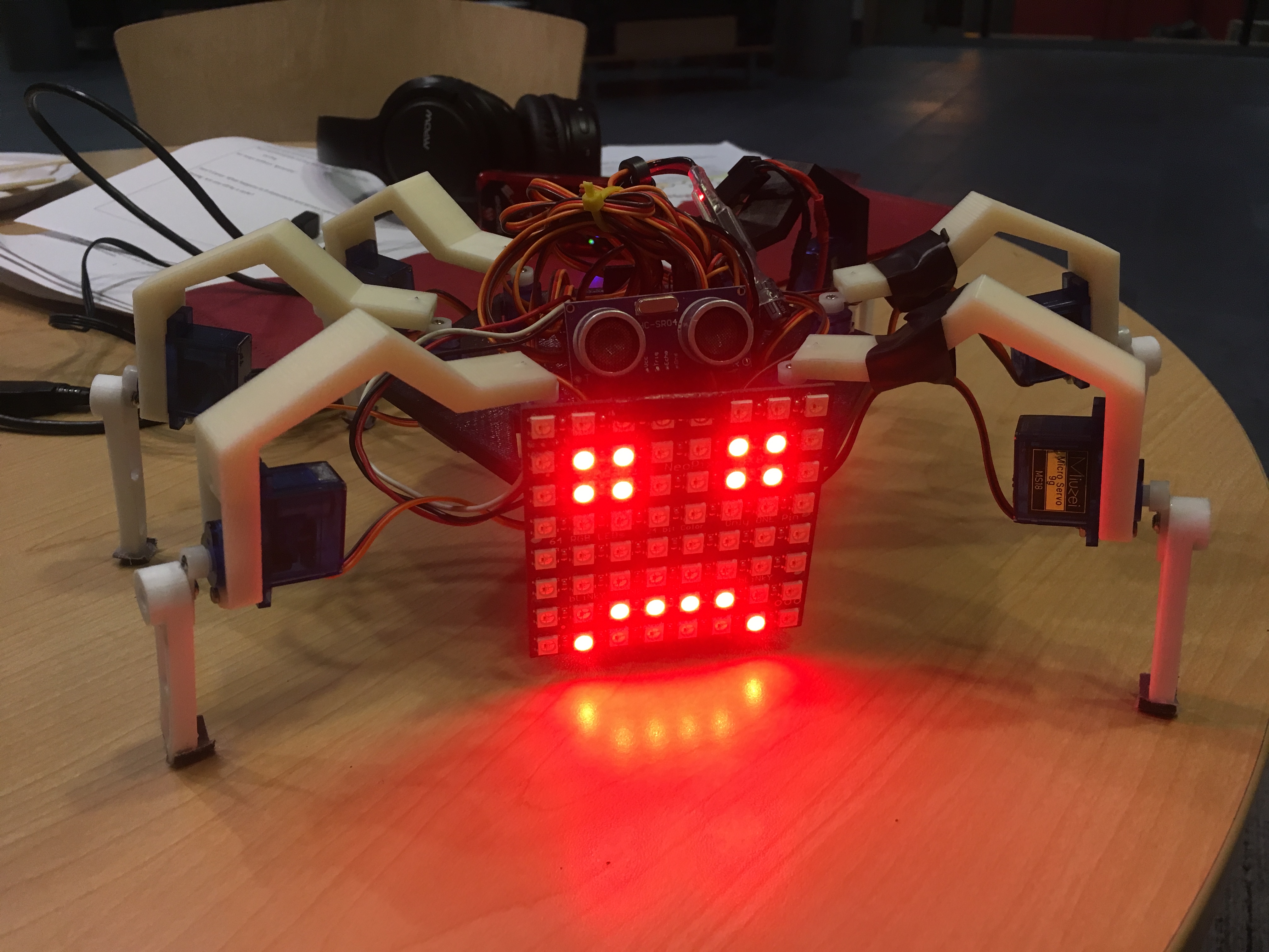
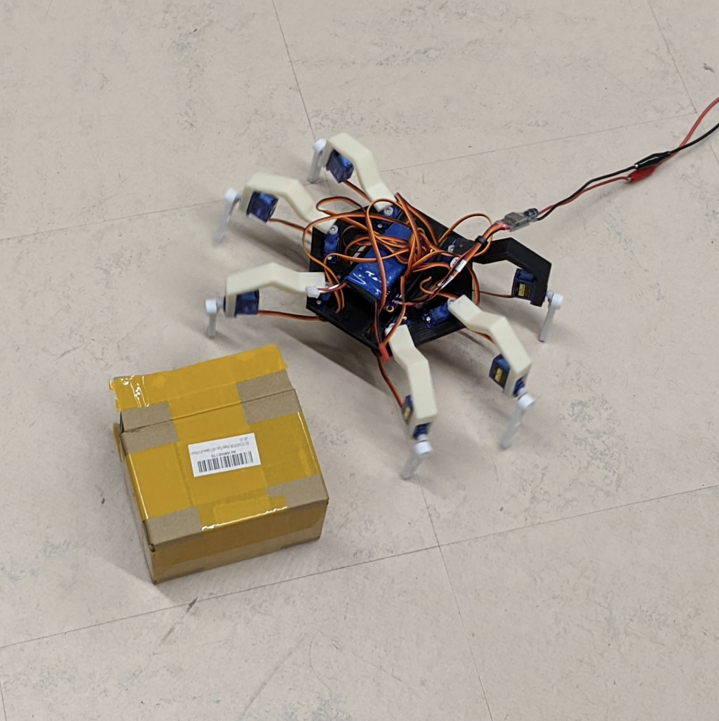
We’ve designed an obstacle-avoiding, mood-displaying hexapod robot. This robot utilizes 12 servo-powered joints to walk on six legs in a spider-like fashion. During its normal walking pattern, Hexapod avoids obstacles in the forward direction via an ultrasonic sensor calibrated to detect objects 20” away. To mimic spider walking patterns, we programmed Hexapod to back up in a randomly decided left or right direction in the presence of an obstacle. Finally, to include the ability to communicate the state of obstacle detection with a user, Hexapod includes an 8x8 LED display to create a mood-dependent face that increases in happiness with the time elapsed since an obstacle was last detected.
Our Team Of Engineers
We are passionate students of engineering at Cornell!
Megan Backus (mb2532)
ECE
Joseph Primmer (jp2228)
also ECE
Kenneth Mao (km63)
yet another ECE
HIGH LEVEL DESIGN
A brief overview of the design considerations for our project
Rationale and The Idea
Our rationale for building this project was simple. We wanted to build a cool looking robot that could fake some basic personality. We can attribute the sources to our ideas for this project to many places like spider/ant/bug walking patterns, video games, and pre-existing robots.
Logical Structure
Our project has a very systematic logical structure. Although there are many different parts to our robot. These parts tended to be very similar to one another. This meant there were many ways we could reduce duplicating work. In hardware these include using the same 2 CADs for all the legs and having a symmetrical design. In software this meant creating macros and abstractions for reducing code duplication.
Background Math
We utilized math in several places. These include doing physics simulations on the mechanical design in ANSYS. We also had to calculate how often to trigger the interrupt service routine for the PWM signals. We calculated this based on how much granularity we needed for the pwm (about 40 different steps within 1ms or around 80 different steps for the entire range of the servo) and how much CPU utilization we were willing to spend. 40 * 1000 = 40kHz so we defined our ISR to go off every 1000 clock cycles. 40MHz / 1000 = 40kHz.
Hardware / Software Tradeoffs
We made a few hardware/software trade offs. These include the trade off between servo granularity (hardware) and ISR CPU utilization (software) as well as using DMA to do pwm (hardware) vs using an ISR (software productivity). With a higher interrupt rate we could have better servo control, but the CPU wouldn’t have time for other tasks, so we chose a smaller granularity to allow the CPU to do other interesting things. We also chose an ISR to generate pwm instead of DMA as using dma would increase software size and complexity and prevented us from implementing other cool features in this short amount of time.
Standards
Some standards relevant to us are the IEEE 802.11 standard used for Wifi and is the standard the esp8266 wifi chip adheres to. The esp8266 chip is also FCC certified and its FCC ID number is 2ADUIESP‐12 and a full compliance report can be found here: FCC Compliance. Although we didn’t end up utilizing the chip, it is still built into our robot and can be utilized in the future. We also used the UART communication protocol used for serial communication between devices. In this project we will use UART to communicate between the esp8266 and the PIC32mx microcontroller. Finally we also used PWM for servo control.
Intellectual Property
There are not very many applicable patents, copyrights, and trademarks. However, we would like to attribute a portion of our code (specifically the neopixel functions) to Bruce Land, who wrote these functions originally for use with a neopixel strip. We reutilized and modified this functionality for use with our neopixel display. We would also like to attribute the design of this website to landingrepo.com from which we found the free template for our website.
HARDWARE/SOFTWARE DESIGN
In depth overview of how certain portions of our hardware and software were designed
There are certain trade offs we made in this project that brought down the “accuracies” of certain subsystems but did not have an impact on the overall performance of the project. These included aspects of our PWM generation, neopixels, and the ultrasonic sensor.
PWM Generation: Granularity of 40-80 steps
Neopixel: Occasionally has some flickering artifacts (can pass as “blinking”)
Ultrasonic Sensor: Only took readings every ~100mS only while going forward
These accuracies and artifacts are discussed more in the software sections.
Safety and Interferance
Our robot design is both safe in interacting with users as well as generally free of interference with other people’s designs. Our current design does not make use of RF transmission currently, so it does not pose any danger of interfering with other projects. If we do plan to add RF in the future it will be a pre FCC approved esp8266 module that is confirmed to meet certain interference mitigation requirements. It is also includes forward obstacle detection so it also does not pose the problem of physically interacting with any other designs.
Our final robot design has a very simple user interface. It utilizes two onboard pushbuttons: one for resetting the entire robot and one for beginning the walk sequence. The reset button cause the robot to initialize to a neutral upright position and a happy face display. Upon pressing the start button, the robot begins to walk forward until it detects an obstacle. When detecting an obstacle approximately 20” away, the robot turns either backwards left or backwards right until the obstacle is no longer detected. When detecting an obstacle for the first time, the robot’s face turns neutral, and after a certain period of time consistently detecting an obstacle has elapsed, the robot’s face turns angry. Pressing the reset button again causes the robot to resume its neutral, stationary stance.
This very simple interface allows the robot to be operated and understood by almost anyone.
Read Our Customer Testimonials
Our clients all love the Hexapod Robot!
The Hexapod robot always helps me cheer up when I'm down!
Jude Thorn - a stock photo
I purchased the Hexapod robot for my son bobbykins, it is the only thing he plays with now!!
Marsha Singer - Mom
Even though I always get the feeling it will jump up and attack me one day, the Hexapod Robot has really proven itself to be a real team player.
Roy Smith - CS Major
At the beginning I thought the price for the Hexapod robot was a bit high, but time and time again it proves its worth!
Ronald Spice - AEM Major
I recommend the Hexapod robot to every business owner who wants to improve moral at their company!
Lindsay Rune - SV CEO
Sometimes the Hexapod robot makes me think really deeply about my place in the universe. I think that's really special.
Ann Black - Philosophy PhD Candidate
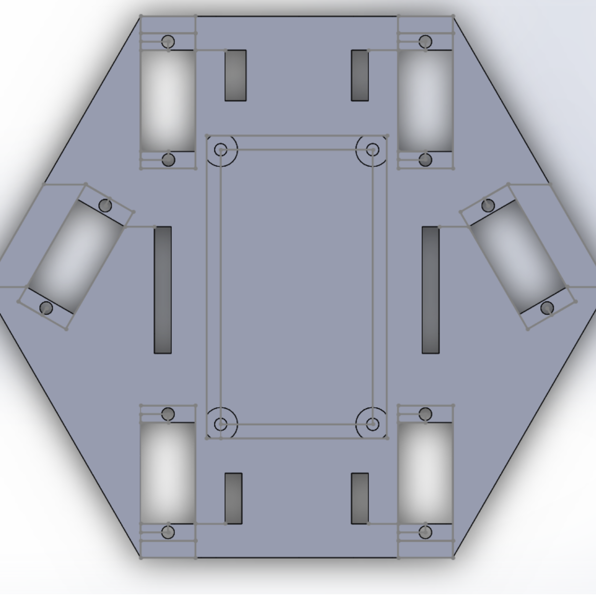
Baseplate Design
The design limiting factor for the base plate was the size of the PCB and the servos. The PCB is placed in the center of the baseplate and the servos are uniformly distributed around the PCB. The factor determining the shape of the baseplate is the number of legs. While it is possible to develop quadra pod, we decided to design a hexapod as more legs would allow us handle more weight, and give us more flexibility when designing out walking algorithm. Because our design incorporated 6 legs, the base plate is a regular hexagon, a hexagon with the same side length all around. The drive shaft of each cylinder is place at the corners of the hexagon in order to evenly distribute load around the hexapod. In order to reduce drifting to the side when walking, the weight is distributed as evenly as possible. The battery, PCB and ultrasonic sonic are placed in the center of the robot. The only exception to this is the middle pair of servos, where the housings of the servos are angled slightly. This was slight tilt will not significantly change the center of mass, and provides space for cable pass through on the longer dimension of the PCB. More cable pass-throughs could be found at the front and rear of the baseplate close to the servos.
We originally intended to buy standoff screws in order to mount the PCB to the baseplate, however we were not able to find an affordable set of screws that would fit our board’s mounting holes. As a result, the board has built in standoffs consisting of a large diameter cylinder to elevate the board off the baseplate, and a smaller diameter cylinder that would pass through the mounting holes of the PCB. The smaller diameter cylinder was printed to be slightly larger than the PCB mounting hole so the friction between the standoff and the PCB would keep the board in place. In order to mount the servos, we measured the dimensions of the housing and utilized the screw holes as mounting points. The baseplate through holes are not threaded, so we use a washer on the other side of the base plate to secure the motor to the base plate. Currently the battery is velcroed to the center of the base plate on the opposite side of the PCB. This allows for quick access when we need to charge it. The fill of the base plate is 70%. The fill could be reduced to save weight.
A 2nd version has been designed with a battery cubby, larger cable pass through as well as extra mounting points for a dome that would have been used if rolling was implemented. Due to time constraints and slow 3D print turnaround times we were unable to implement these features.
.
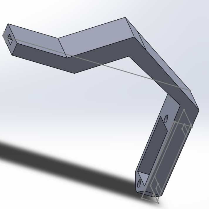
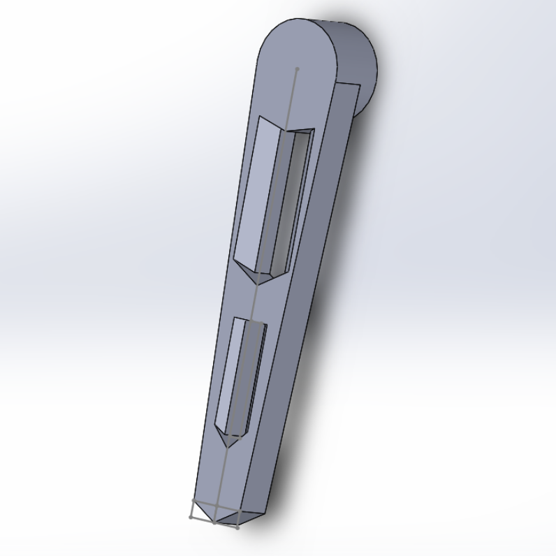
Mid Leg
The first leg link attached to the base plate was designed with compliant design in mind. In the case where excess pressure is applied to the robot, the crease in the leg will flex as opposed to jamming the servos. This design is also significantly more cosmetically appealing than simply having an “L” shaped leg as it gives the appearance that our robot has 3 segments per leg and that each leg has 6 degrees of freedom. In reality, each leg is comprised of two revolute controlled joints (servos) in different planes, and thus only has 2 degrees of freedom. In order to attach the servo to the actual leg we used the mounting pieces that came with servos. The legs had a small hole that we screwed into said mounting pieces.
The proportion of the first leg link we were chosen with rolling capabilities in mind. Together the height of the first leg link and the second added up to be 90mm which was longer than half the distance from one flat side of the hexagon to another. This was done so that the robot could flip itself to the back. As for the horizontal “reach” of or length of the first leg link it was chosen to be almost the same length as the side of the hexagon. This provided the spider with an interesting wide stance look, without applying too much torque to the servos. The width component of the first leg link was the width of the servo. We made it just wide enough to fit the servo within the width of the leg. Much like the baseplate, we used nuts screws, and the built in mounting points of the servos to attach the servo to the leg link.
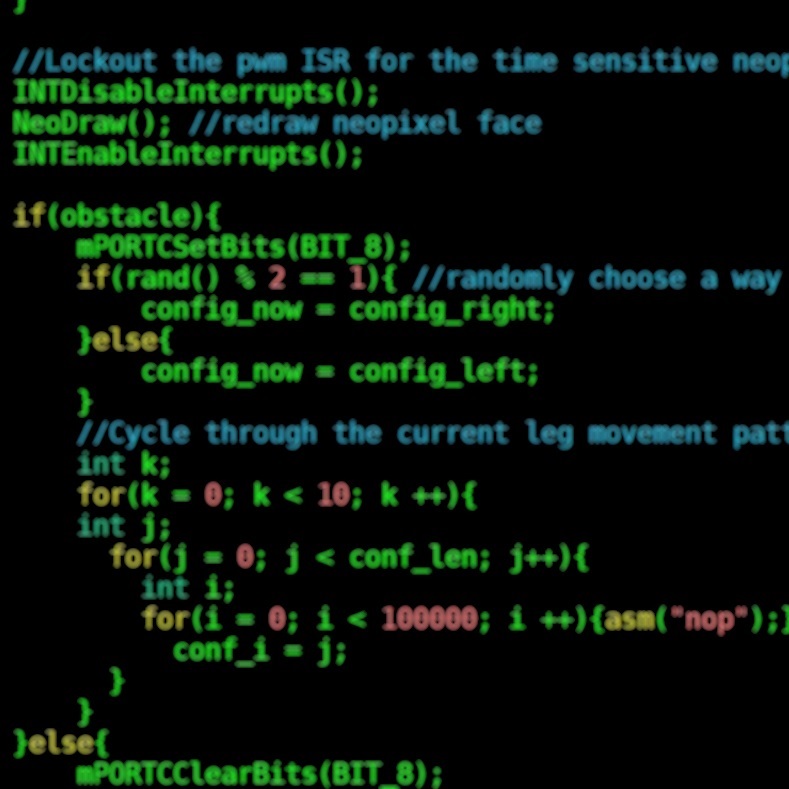
PWM Signals
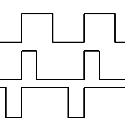
PWM for our robot was generated using an interrupt service routine occuring at a rate of 40kHz. Since the standard frequency for pwm is 50Hz we increment a variable in the ISR to go up to 800, then go back to zero (40,000 / 800 = 50). Then, since pwm depends on a 1-2ms window within the 20ms cycle (1/50Hz * 1000ms), we get about 40-80 steps of granularity in the servo control. This is because we have the servo pins output high whenever they are below a certain “change value” on the incrementing pwm variable.
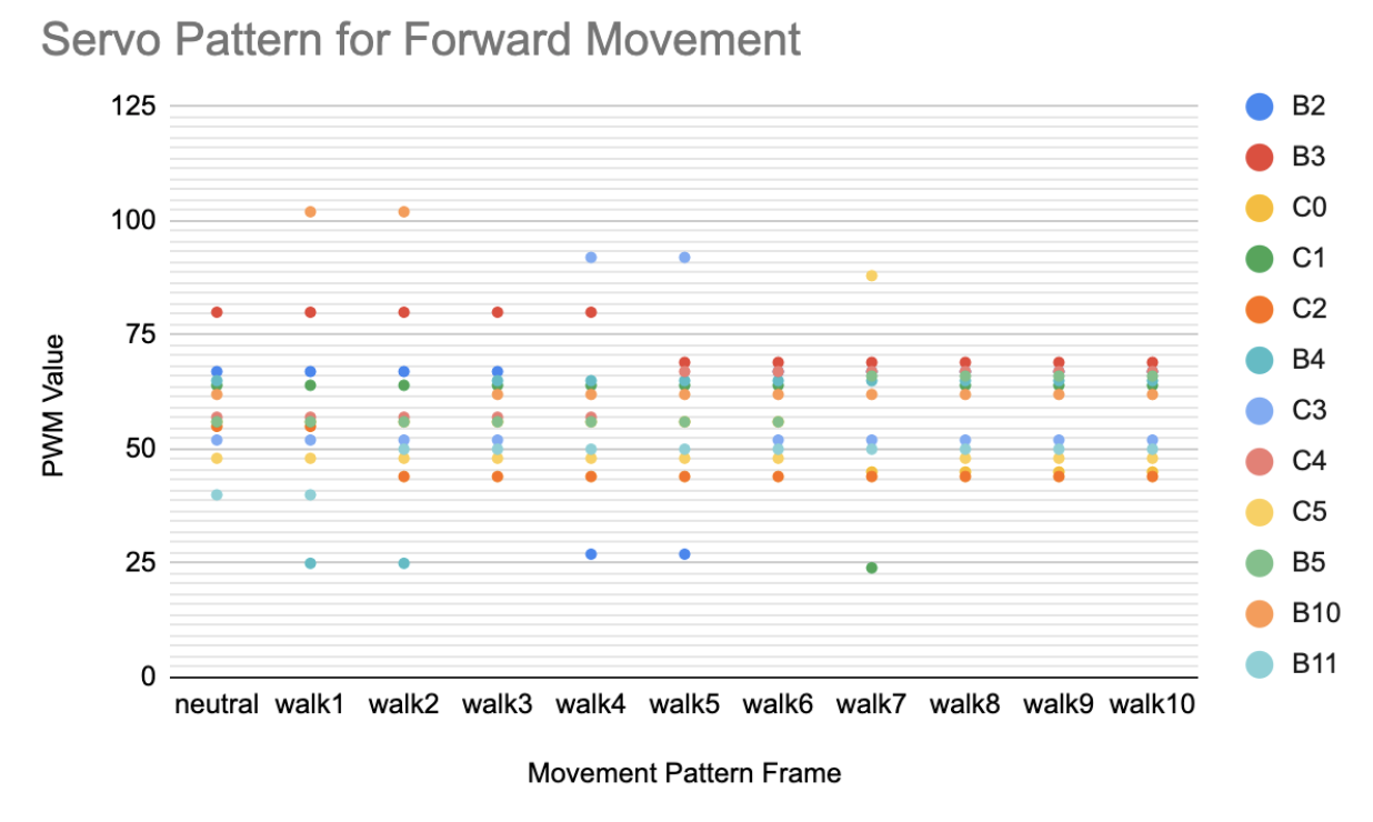
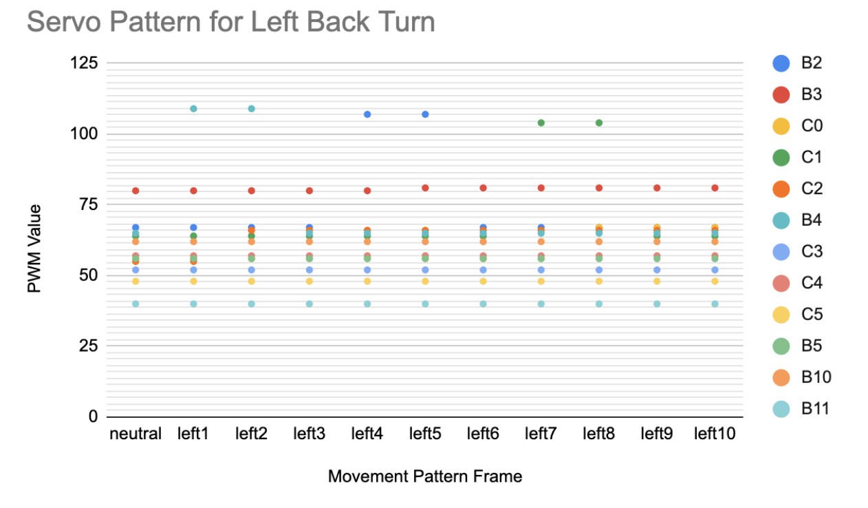
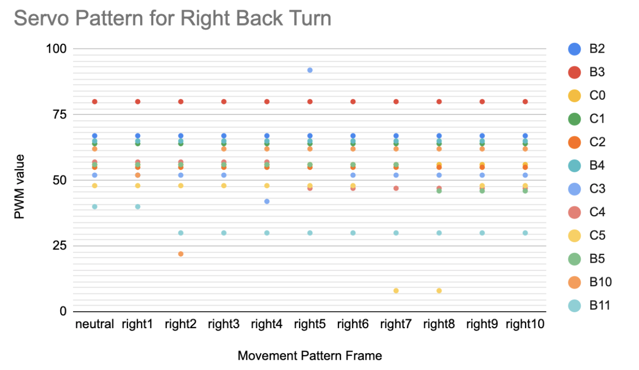
The preset leg movement patterns for the servos are in the form of an array of these change values (neutral), or and offset value from the neutral change values. The neutral change values represent the values at which the robot is in a neutral standing position with all its legs straight down. This allows us to very easily calibrate the robot’s servos in case they drift off center.
After calibrating our servos, we found via experimentation series’ of pwm patterns for each of the servos for our forward, back right, and back left movements. For each of the servos, we experimentally determined a neutral position and offsets from neutral that correspond to each frame of a specific movement. Each movement requires 10 frames. The following graphs depict the state of the servos at each from for each movement. The robot diagram displays which GPIO pins correspond to which servo spatially on the robot.
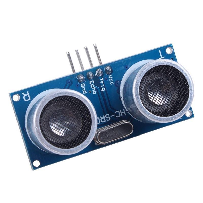
Ultrasonic Sensor
The ultrasonic sensor we chose is an HC-SR04 sensor. This sensor can send out an ultrasonic pulse when it is given a 10 microsecond pulse on its trigger pin. Then when it receives the echo from the pulse it will output a pulse on its echo pin who’s high time is proportional to the distance the sensor detected. We could read this pin in one of two ways: either we could use the input change feature to capture using interrupts, or we could perform the same operations serially with all the other functionalities on the CPU. We decided to go with the latter approach because when we tried to use the interrupt based method the ultrasonic ISR would keep interrupting the PWM ISR or vice versa leading to an undefined response.
Therefore, we decided that during every cycle through the forward walking pattern the robot would take an ultrasonic reading before going forward again. This way the ultrasonic readings wouldn’t interfere with any other operations and CPU utilization was reduced. Since this is done every time the robot moves forward, its ability to react to objects isn’t reduced and since it happens so fast, this reading isn’t perceptible even though it is technically a blocking operation.
We took the reading by sending out a pulse, then waiting for a high signal. Once we have received a high signal, we would reset a timer to zero and start it. Finally when the signal went low, we would stop it and store the value as a distance.
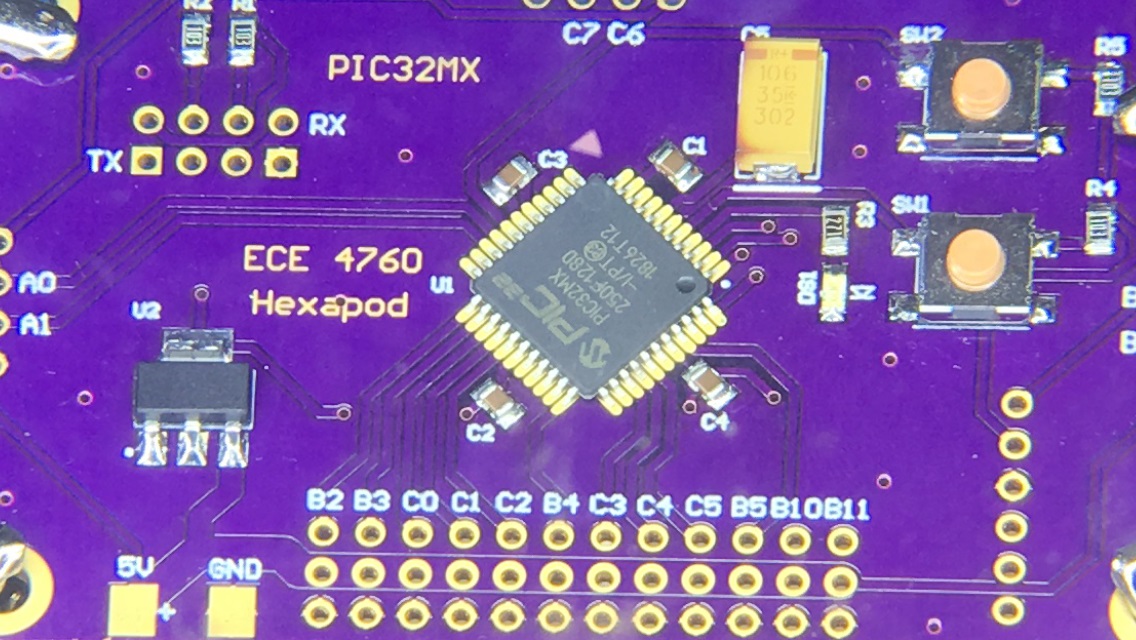
Circuit Board Design
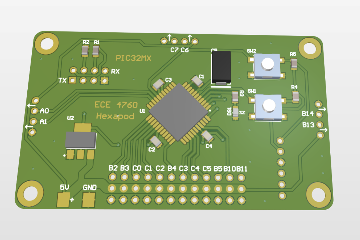
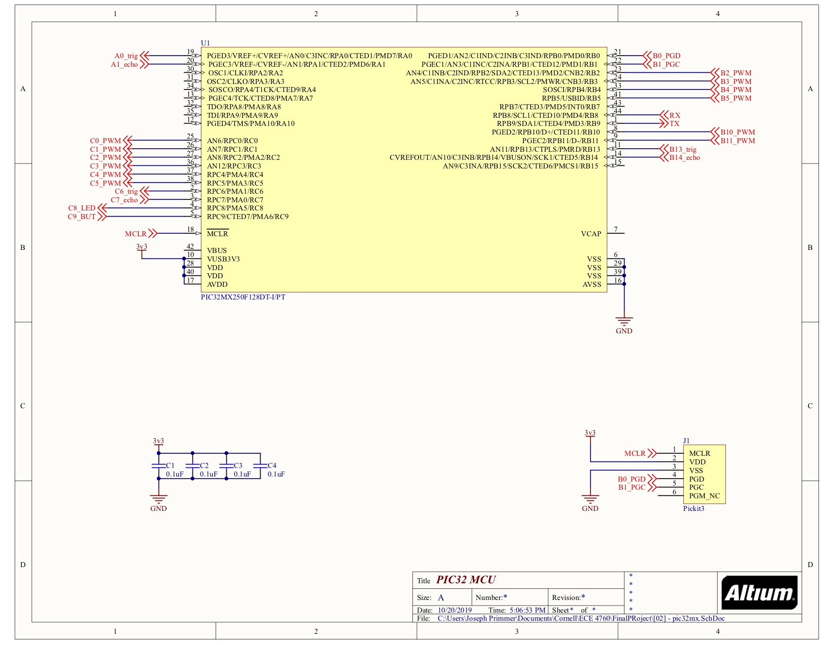
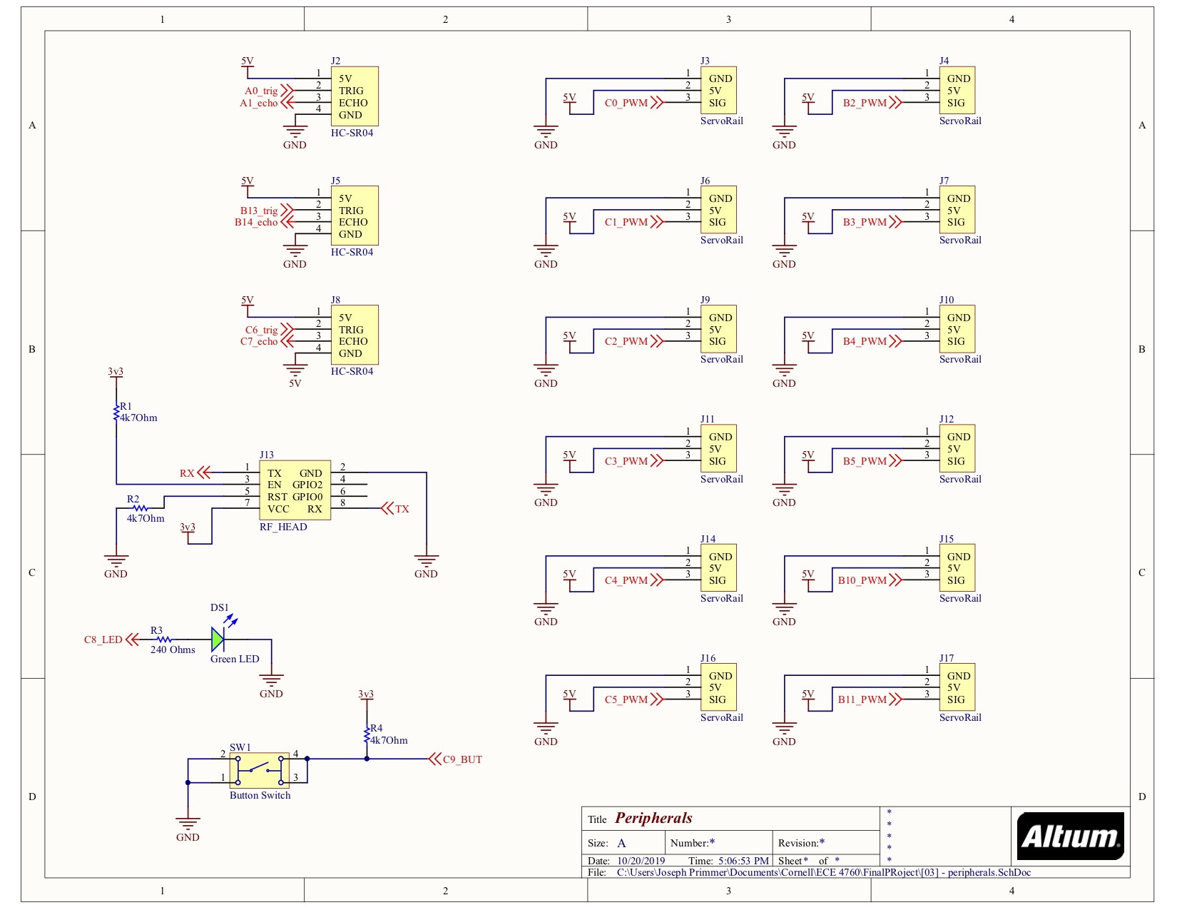
For our robot we decided to design a custom printed circuit board instead of using the big board or small board. This is because we needed our robot to be light and have a small form factor in order to allow the best range of movement. The PCB we designed is a two layer FR4 PCB and was designed in Altium Designer. This PCB includes the SMD PIC32MX250F128D, connections from GPIO pins of the microcontroller for easy peripheral connection, a programming header meant to be compatible with a PicKit3, broken out connections for power, a servo header for each of the 12 servos, a 3.3V LDO voltage regulator, two buttons (for reset and start signals), and a debug LED.
Design considerations for the electronics portion of this project included ensuring proper power delivery, reducing the likelihood of power surges, and reducing interference to the electronics. We met these considerations with the proper circuit design techniques. By ensuring that all the servo connections had thick copper traces we could make sure it would handle a lot of power. We also made sure to include a 10uF tantalum smoothing capacitor to help mitigate power surges. Finally we made sure that all power pins on the microcontrollers had proper bypass capacitors to reduce interference on the power inputs.
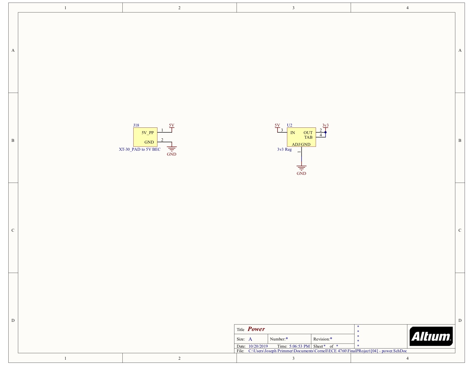
See Appendix C for the circuit board schematics.
Neopixel Display
The adafruit neopixel display we used for the robot face use a specialized LED called the WS2812B. These use a one wire protocol where a pulse on or pulse off for a certain time indicate whether a bit has been sent or not.
We adapted code written by Bruce Land that allows us to do this. We use 3 arrays to represent the different color values that we send over the wire and we update these arrays with values that represent the different faces. We have also have 3 arrays that hold the indices within the color arrays to change in order to achieve a certain face.
We decide which face to display based on a mood variable within our program. This mood variable would change based on how many objects the hexapod has recently seen. Whenever it sees objects, the mood variable gets decremented, whenever it doesn’t the mood variable gets incremented. Certain ranges of the mood variable then correspond with different face displays.
The neopixel display also has some visual artifacts in the form of flickering and some incorrect LEDs lighting up every once in a while. This was an issue from the code we adopted and we couldn’t figure out a fix. However, this wasn’t that high of a priority as the flickering could pass as the robot blinking and it didn’t affect any major functionality.
Distal Leg
The second leg link had much fewer design constraints than the two other parts. The front and rear pairs of legs had a second leg link length of 50 mm, while the middle pair of legs had a length of 55mm. This difference in length was to aid in rolling, as the middle pair of legs would need help push the robot even farther to its backside. The second leg links were designed to be mostly hollow and printed out of TPU so it deformes slightly to better grip the surface.
Despite making the 2nd leg link out of TPU and designing it to conform to the ground we our robot kept slipping. The feet of the robots had not enough grip for the speed at which the servo moves. In order to correct for this we tried adding electric tape or sandpaper to the bottom of the feet. Sandpaper proved to be a better solution, and we decided to add it to all the feet of the robot.
Mechanical Overview
The chassis of the robot is comprised of 3 parts; the hexagonal base plate, the first leg link, and the second leg link. There were 3 main considerations for designing the chassis and the legs of the robot; mechanical reliability/ resilience, rolling capabilities, and cosmetics. The most important factor to consider was mechanical resilience. During the end of the semester, all 3D printers on the engineering campus are have a backlog of prints going as far back as 3 weeks. We had a 2nd version of parts to print that was sent out to print on November 29th, but received our parts on December 13. Having one part fail or not be functional and require a reprint would severely bottleneck the software development of this project. With this in mind, our team began designing the 3D printed parts before the end completion of lab 3. Every component was first hand sketched, and measurements were taken with calipers.
The original walking algorithm we came up was one with continuous movement. The left side of the robot and the right side of the robot had the same cycles, however left side would be one stage behind the right side. (Refer to mechanical sketches in the mechanical overview). While this approach did allow for faster and continuous movement the robot would always drift to one side. Re-tuneing the amount of degrees turned for each servo was not a reliable option to correct this, as our servos are not precise, and overtime the chamber of each leg changed with usage. As a result we made both the left side and the right side of the robot move in sync with each other. This means our robot does not move continuously, instead all of the legs move forward, then the body is “pulled” forward to the position of the legs. This “burst” of speed can be seen in videos when slowed down.
Here are the preliminary design sketches we used in initially planning our CAD designs and walking algorithms:
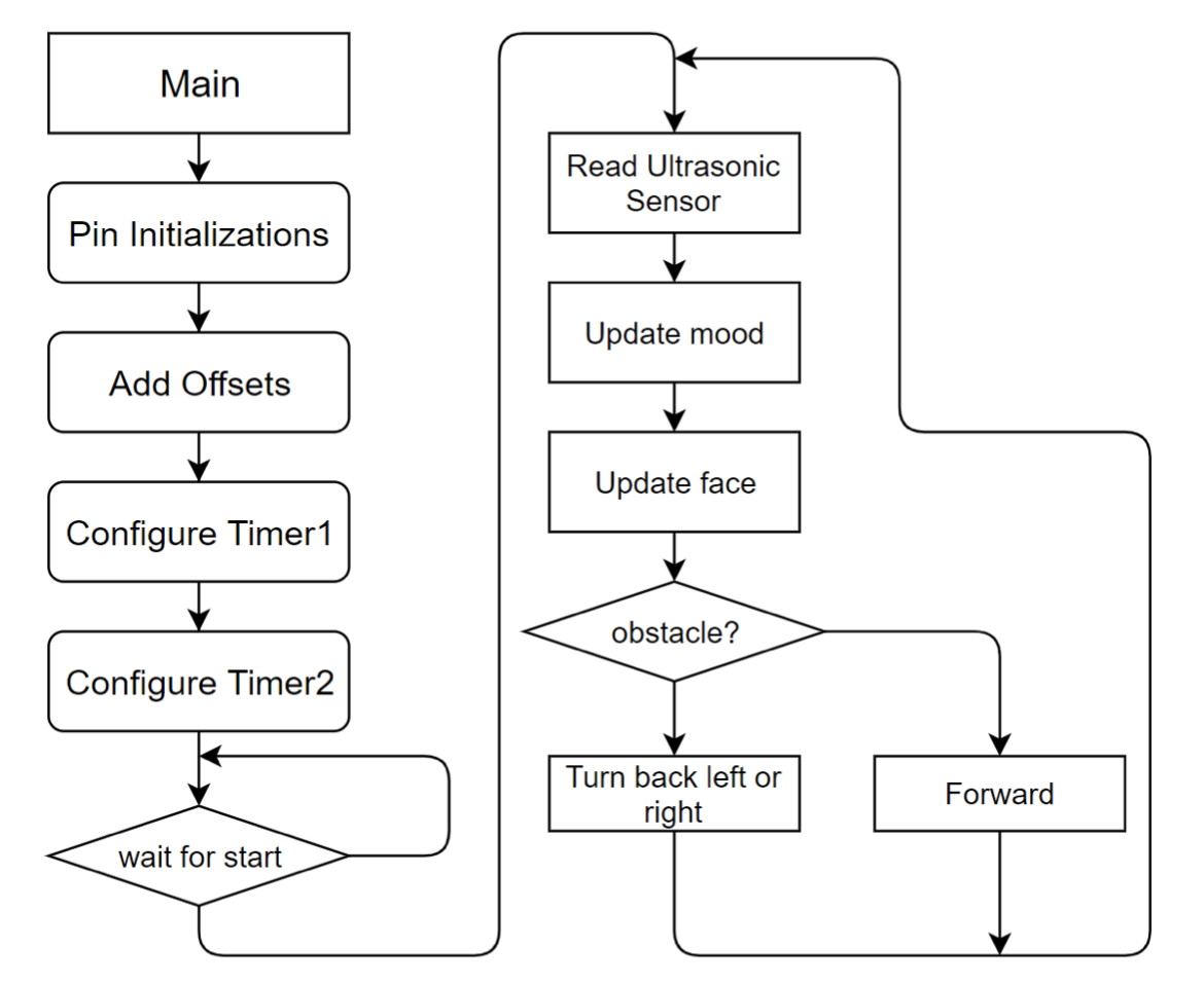
Our software is split into two main parts, the initialization, then the obstacle avoidance. The initialization involves initializing the GPIO pins, adding offsets to the leg movement patterns, and configuring the timers. The Obstacle avoidance portion involves reading the ultrasonic sensor, updating the mood and face, then making a movement decision based on whether or not it has seen an object.
ABOUT
Conclusion
Though our final design changed slightly from our initial project proposal, it meets all of the baseline design expectations we intended to carry out. When planning our project we expected to create a hexapod robot capable of a stable forward walking movement using the standard 2-joint-per-leg mechanical hexapod model. We also planned to implement several different movement patterns, including turning and backing up. We met these initial expectations for construction and movement in our final design. In addition, we had several other ideas for additional robot features in our design proposal, some of which we implemented and some of which we decided against using while working on the project.
One of the features from our proposal that we decided to implement is ultrasonic obstacle detection. We deviated slightly from our initial plan by later deciding against using three ultrasonic sensors for obstacle avoidance in the front, left, and right directions in favor of using only one sensor in the forward direction in order to free up header-connected GPIO pins on the PIC32 for other peripherals. Due to time constraints limiting our ability to 3D-print a redesign of our hexapod legs, we were not able to implement a rolling movement as we intended. One feature we added to our design post our initial proposal is the Neopixel Array for displaying robot mood. The removal of the additional ultrasonic sensors made it possible for us to interface with with this LED array.
Our final hardware and software design has very few intellectual property considerations as almost all of the code and mechanical design for the project was created from scratch. We did not use any code in the public domain or reverse engineer an existing project. While we utilized some background information about mechanical design and proportions from various sources (see Appendix), the final design was ultimately created by us. As a result, we did not encounter any patent or trademark issues and our final design is open to any publishing opportunities of its own.
If we were to redo or continue this project, we would add in some of the additional features we were unable to implement, including WiFi control using an ESP8266 module, hexapod rolling, and obstacle avoidance in multiple directions. This would involve modifying slightly our PCB design to allow for more peripheral devices, possibly modifying our software to allow our existing operations to require less of the total CPU time, and redesigning our robot legs.
Ethical, Safety, and Legal Considerations:
Throughout the course of our project development we complied with the IEEE Code of Ethics.
Our final project is a very safe design, as the hexapod is very unlikely to run into anyone and thing given its obstacle avoidance feature, it has a bright LED display that indicates its presence, and the servos used to power the legs have enough static torque to move the legs but are not powerful enough to pose any risk of injury. This complies with IEEE ethics standards (IEEE Ethics Standards 1 and 9). In the hope of allowing others to recreate this hexapod design, we provide detailed descriptions of hardware design as well as CAD design files and circuit schematics and have made our code open source on Github.
The hexapod design has very few safety concerns as well as it is not bio-connected. The robot runs very little risk of running into anyone or anything with its forward obstacle detection for forward movement. To avoid accidental shorts, we have made sure to carefully insulate all wires in our power circuitry and added an easy-to-use Microfit connector to connect and disconnect our LiPo battery to our BEC. In order to prevent our LED display from being blinding (as Neopixel LEDs are normally very bright), we wrapped the array with a semi-transparent paper cloth to diffuse the light.
For similar reasons, our project does not have any legal considerations as it does not connect to humans or other vehicles and does not utilize a transmitter.
Appendix
Appendix A.
The group approves this report for inclusion on the course website. The group approves the video for inclusion on the course youtube channel.
Appendix B.
Commented Code
Appendix C.
Schematics
Appendix D.
Bill of Materials
Part
Part Number
Vendor
Price
PIC32 Microcontroller
PIC32MX250F128D
Digikey
$4.24
Custom prototype PCB
N/A
OshPark
$8.33
SG90S micro servo (x12)
SG90S
Miuzei
$21.60
3D printed hexapod baseplate and legs
N/A
*printed in Cornell Rapid Prototyping Lab
$0
Battery Eliminator Circuit
CSE010-0154-00
Castle Creations
$34.00
Ultrasonic Sensor
HCSR04
WYPH
$1.20
M2 Machine Screws
N/A
*taken from lab
$0
8x8 Neopixel Array
N/A
Adafruit
$34.95
7.4V Lipo Battery
A949
Bloomikey
$12.50
Various SMD Electronic components (capacitors, resistors, push buttons, male/female headers)