Welcome To Our Project
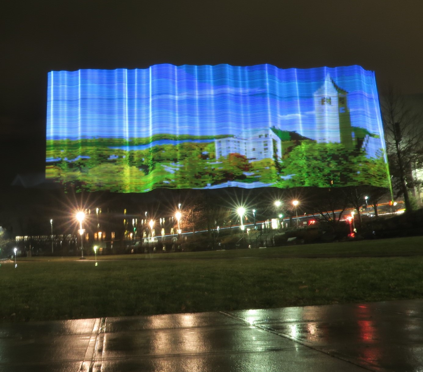
Using a one-meter strip of LEDs on a mobile cart, we created custom light paintings using long-exposure photography from images uploaded by the user.
Welcome
High Level Design
The painting is created by a vertical pole with a flashing one-meter LED strip attached to a cart being pushed by two motors. A user can use their DSLR camera to view the long exposure effect. To upload an image, the user specifies a URL through SSH on a Raspberry Pi 0 W which receives and resizes the image. The Raspberry Pi then sends the RGB image data to the PIC 32 in parallel, which is connected to the LED strip and motors. The image content is sent as an 8-bit RGB value per pixel. The PIC 32 converts the pixel data into RGB values for the LED strip and changes the colors at an appropriate speed to create an image while the motors move the entire apparatus horizontally. By moving the strip horizontally, we were able to recreate images of varying widths.
Hardware
Our mechanical design, parallel communication connection, motor control circuit, LED strip circuit, and our power solution.
HardWare
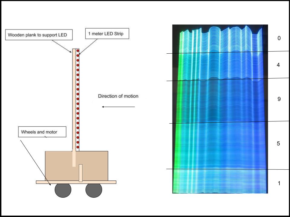
Right: Tissue paper layering test showing the result and the number of layers used.
Mechanical Design
We mounted the 144 LED/meter dotStar strip on a 3 foot piece of wood. The LED stick was mounted onto a cardboard box that contained the Raspberry Pi, PIC 32, breadboard, and power supplies. The box sat on a wood frame that was connected to the motors and wheels, allowing the mechanism to move in one direction of any distance.
We also added five layers of tissue paper on the LED strip to help diffuse the light and create a more blended image without sacrificing light intensity.
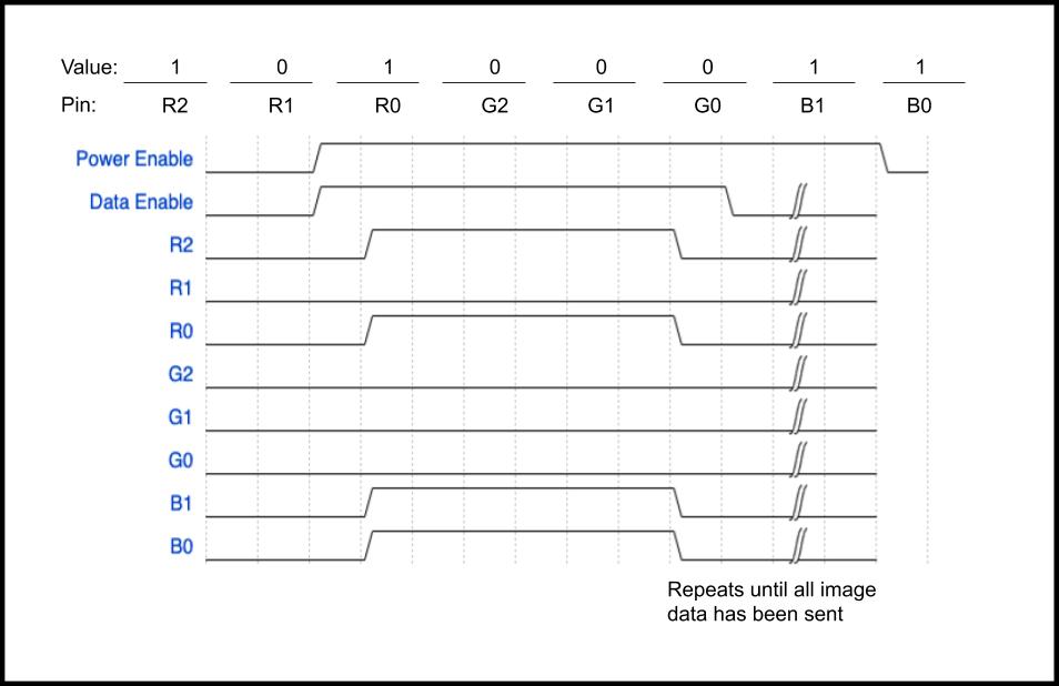
Bottom: Parallel connection data lines, showing that the first LED in the first column will be purple.
Parallel Communication
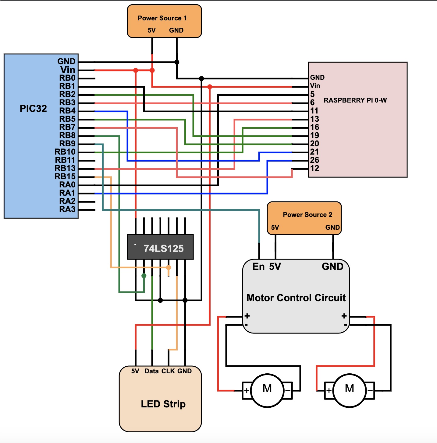
We decided to connect the Raspberry Pi Zero to the PIC 32 through parallel connection with two different enable pins. To accomplish this, we sent an 8-bit RGB value through 8 GPIO ports, with a data enable pin than indicated when the color for each LED was sent, and a power enable pin that indicated when to start and stop the motors. This pin allowed us to start the motors upon data transfer and stop the motors once all the data has been sent and the image has completed. Each of these connections had a 330Ω resistor between the pins to limit current and protect the microcontrollers.
The power enable pin controls when the motors are turned on and off. The two motors are connected in parallel while being isolated from the PIC 32 to protect it from inductive currents. We used the motor control circuit from the ECE 4760 Lab 3 webpage.
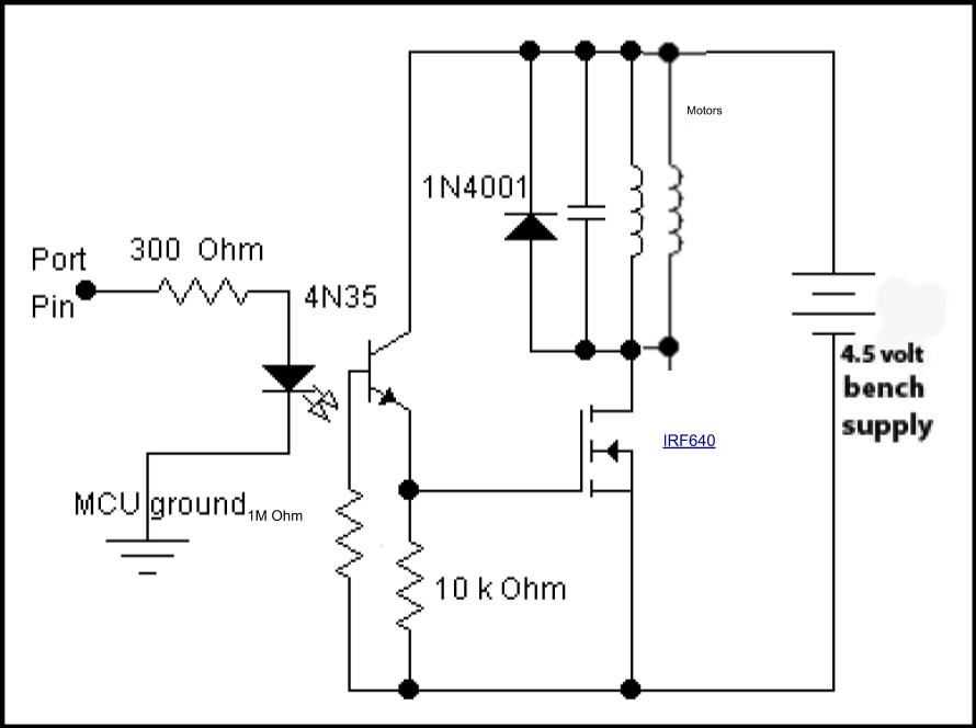
Motor Control
The power enable pin controls when the motors are turned on and off. The two motors are connected in parallel while the motors are controlled by a PWM output with a 1 K Hz frequency. With a 40M Hz clock frequency, this means that the PWM output can have a duty-cycle ranging from 0 to 39999. Because DC motors are inductive loads, the release of the stored energy causes harmful voltage spikes that could damage the MCU. To protect the MCU, an optoisolator is used to electrically isolate the motor from the MCU. The optoisolator used is the 4N35. Additionally, a diode and capacitor were placed in parallel to the motor to moderate the motor voltage during the PWM transitions. A MOSFET was used to switch the motor on and off using the PWM signal and resistors (300 Ω, 1M Ω, and 10K Ω) were added to protect and optimize the circuit as shown below.
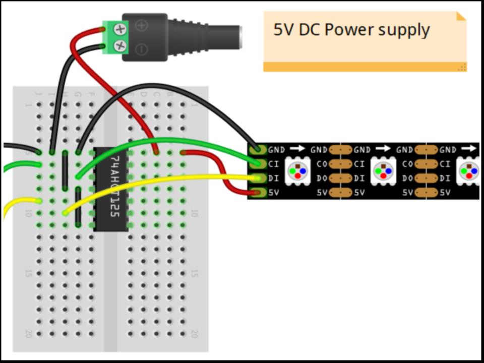
Source: https://learn.adafruit.com/adafruit-dotstar-leds/power-and-connections
LED Strip
The DotStar LED strip was connected to the PIC 32 through a 3.3 to 5 V logic shifter, 74LS125, since the LED strip requires 5V data, and the PIC 32 only outputs 3.3V. The connections are shown in figure 5.
Power
The Raspberry Pi, PIC 32, and LED strip were powered at 5V through a USB connected power bank. This was possible by running the LED strip at the lowest intensity, where it would draw less than one amp. The motors were also powered using a separate 5V power bank that was connected through a USB cable.
Software
All the software we ran on the PIC32 and Raspberry Pi 0 W.
SoftWare
read_pixeldata
This function is designed to read pixel RGB data from a wired parallel communication connection to the Raspberry Pi 0 W. Each call to read_pixeldata reads the parallel data lines once, corresponding to one pixel worth of RGB data, so, to get RGB data for one column of 144 pixels in an image, you must call read_pixeldata 144 times. Inside read_pixeldata, the function checks the data enable pin and if the result is 0, sits in a while loop until the data enable pin goes high, meaning all 8 of the parallel input pins have been set to their correct values by the Raspberry Pi. While waiting for the data enable pin, the function also checks the power enable pin and if that is low, turns off the motors. Once the data enable is high, the PIC will read all 8 input pins, 3 for red, 3 for green, and 2 for blue, with each pin corresponding to a bit of the color value for that pixel. After reading all the pins, the function concatenates the bits for each color and scales the value so each color’s value is between 0 and 255. Before returning the function waits for the Pi to set the data enable pin to low, signifying the end of that pixel’s transmission.
set_pixel_rgb
After read_pixeldata returns with one pixel’s RGB data, setpixel_rgb is called to add that data to a global pixel array which will hold all 144 pixels RGB data. Like read_pixeldata, this function will add one pixel worth of RGB data, so it must be called 144 times to set all the LEDs on the strip. This function was given to us by Bruce Land as part of his DotStar LED strip walkthrough.
write_pixels
After all 144 LEDs/pixels have been read and set, the program still needs to perform the SPI transfer to the strip to actually display these pixels. Before writing the LED data to the strip, the thread must first start the motors now that all the first column’s worth of RGB data is ready. The thread checks that the poser enable pin is high and if so, turns on the motors by changing the pwm_on_time to 15,000. Once the motors are running, write_pixels takes the now full global pixel array and sends it out through the SPI channel to the strip. First, in accordance with the DotStar SPI protocol, a START_FRAME is transferred, followed by 144 PIXEL_FRAMES which contain one LED worth of RGB data each. Finally, a STOP_FRAME is transferred, signifying the end of the transmission and visually lighting the strip.
The above process reads, sets, and writes RGB data for one whole strip, which corresponds to one column of the image. To form a whole image, we must repeat this entire process for however many columns there are in the image.
PIC32
On the PIC 32, we ran a uni-threaded program. The program contains a few initial setup calls to open timers and declare input pins, before than starting one thread. Although this program could have been made with no threading library, we decided to include the protothreads library due to our familiarity and experience with the library and the negligible disadvantages of unnecessarily using threading in this application.
Initializations
The program begins by opening Timer 2 with a generate period of 40,000, which corresponds to a frequency of about 1KHz. This timer is used to trigger an ISR which generates the PWM pulses necessary for precise motor control. After opening the timer, the program continues to open Output Compare 3, which is used to send the PWM signal to the motor control circuit. The output compare works off of a pwm_on_time, which corresponds to the amount of time to hold the PWM signal high, translating to a faster motor. The motors should be off initialing, so pwm_on_time is set to 0 at first. After opening the timer and output compare, the last thing to initialize is the SPI channel used to send data to the DotStar LED strip. We chose SPI channel 2 for the LED strip because the onboard TFT display on our PIC32 Big Board uses SPI channel 1, and we wanted to use this display for debugging purposes. After these three modules are open and configured, we are already to start our lone thread.
Thread
The thread starts by initializing the red, green, and blue (RGB) values of all pixels to 0, corresponding to a completely black or “off” strip. After this initialization, the thread goes into a while(1) loop where it uses function calls to read RGB data, set RGB data, and write RGB data. The thread accomplishes this through repetitive function calls to three functions: read_pixeldata and set_pixel_rgb, and write_pixels.

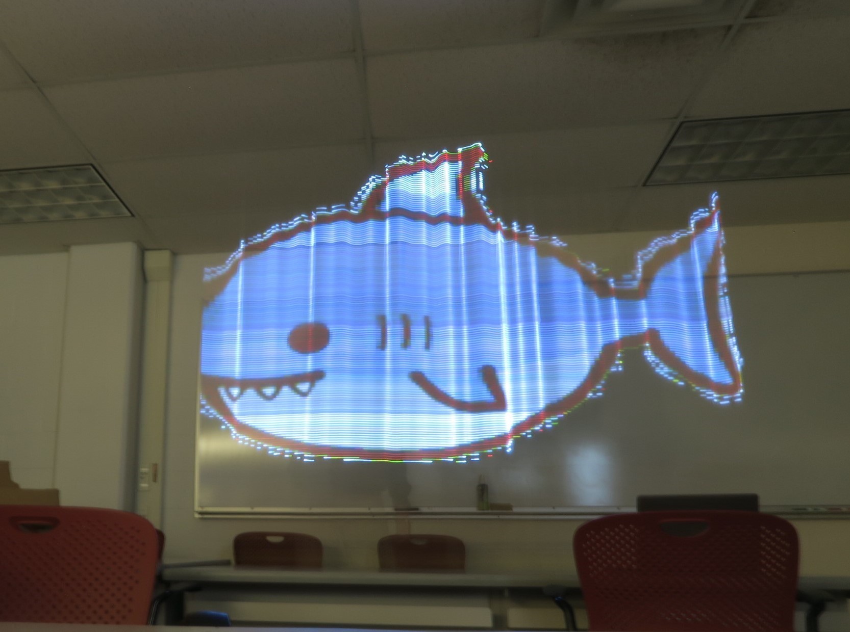
Right: The image uploaded to the PIC
Raspberry Pi
A Raspberry Pi 0 W was used to retrieve the images from the internet and parse and format the RGB data to send to the PIC 32 for display. All of the necessary code was condensed into a single .py file that was run wirelessly through SSH. To begin, the user can specify a url of an image and the Pi will download it and rename it to a user-specified file name. Once the file is downloaded on the Pi, it will prompt the user for a filename to display using theDotStar strip. After opening the file, the program uses the Pillow, a fork of the Python Image Library (PIL) to resize the image to fit the 144 pixel height constraint. Then, the program iterates over all the pixels in the image and saves their scaled RGB data. After saving all the RGB data, a starting LED sequence is sent to the PIC to visually indicate to the photographer to start their exposure. Once one column’s worth of data is transferred the data enable pin goes high then low, to signal that the data lines are all valid values for the PIC to read. Similar to on the PIC, once all this data is transmitted, the process has to be repeated for as many columns as the image has, after which the power enable line will be set low and the PIC will stop the motors.
Results
It works!
Results
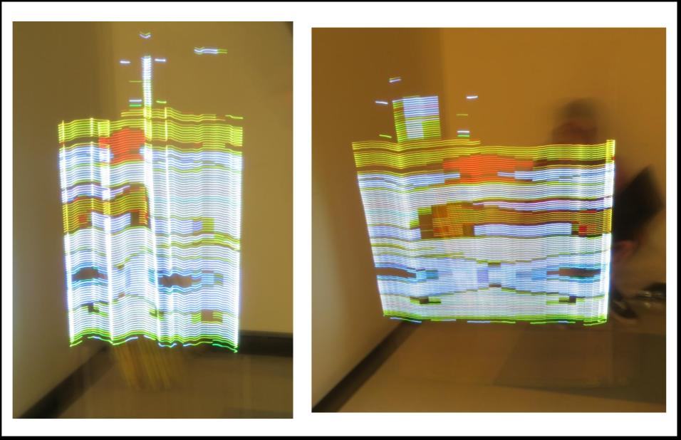
Right: Column delay at .5 seconds
Results
The DotStar Light Painter was able to produce images effectively. However, because we had to reduce the color from 24 total RGB bits to 8 total RGB bits, some color accuracy is lost. Additionally, because we only had 144 LEDs per meter, resolution was also lost (depending upon the original resolution of the image). To increase the resolution, another LED strip could be added. Also, the LED strip could have performed at a higher speed if we had the Raspberry Pi send all the image data at once, however, since the Raspberry Pi sends the data column by column, there is a bit of delay. We did reduce the delay between each column sent from 0.5 seconds to .05 seconds, which shrunk the width of the image.
However, sending data column by column with our slow motors worked to our advantage. The slow speed of the motors was due to too much stress from the torque of the box and strip, so motors with a higher torque tolerance would also have allowed us to better tune the images. Lastly, our mechanical design could have been sturdier. As you can see in the images, the cart rocked side to side as it moved, creating warped images. This could have been prevented through a sturdier design and better materials.

Conclusion
We are very pleased with how our project turned out. We successfully programmed and built a mechanism to draw any image with a LED strip and a long exposure camera. We are pleasantly surprised at the definition of the images we were able to draw with our limited resolution.
Conclusion
Future Considerations
In future iterations of this project, the biggest thing we would like to improve is the mechanical design. Although our design was satisfactory, there were problems with the LED strip shaking while the motors were on, due to the high center of gravity. Additionally, stronger motors would be necessary, as we ended up blowing out our cheap DC motors from the load of the box and strip. Another interesting improvement would be using more LEDs to improve the resolution of the image, although then the machine would be over two meters tall, which could cause maneuverability issues indoors.
Ethics, Safety and the Law
Our project is in accordance with IEEE Code of Ethics, as well as all legal standards. The motors on our project operate at a slow speed and the intensity of the LEDs are low enough that our project could not cause any conceivable health or safety risk.
Intellectual Property
We did reuse some code from Bruce Land’s tutorial on “Driving Pixel Display Strips.” This code is publically available to us on his course website and we have clearly stated the two functions of his that we incorporate into our code. We are not seeking any patent copyright protection on our project design at this time. Additionally, some of the images we used to display on the strip are not our own. However, the long exposure pictures we took represent our own artwork, and we do not intend to use these images for any commercial purpose, so the use of copyrighted images in our project is legally acceptable.
Appendix A
The group approves this report for inclusion on the course website.
The group approves the video for inclusion on the course youtube channel.
Appendix
Appendix B
Check out the code!
Appendix C
Appendix D
| Material | Source | Price |
|---|---|---|
| DotStar 144 LED/Meter Strip | Adafruit | $49.95 |
| Raspberry Pi Zero W | Adafruit | $10 |
| 1 Meter Wooden Plank | Loews | $3.96 |
| Tamiya DC Motor (X2) | Lab | $0 |
| 8x8x8 Cardboard Box | FedEx | $1.75 |
| 5V 2.1A PureGear Battery Pack | The Cornell Store | $19.95 |
| 5V 1A Battery Pack | Owen | $0 |
| Tamiya Wheel (X4) | Lab | $0 |
| MicroStickII | Lab | $1 |
| PIC 32 | Lab | $5 |
| Big Board | Lab | $10 |
| White Bread Board | Lab | $6 |
| Jumper Cables (30) | Lab | $3 |
| USB connectors (2) | Lab | $0 |
| Total: | $110.61 |
Appendix E
Python code: Owen
PIC code: Owen & Maia
Wiring: Maia
Soldering: Maia
Assembly: Owen & Maia
Website: Owen & Maia
Appendix F
| Product/Use | Data Sheet/ Documentation | Code | |
|---|---|---|---|
| Adafruit DotStar | ECE 4760 LED Strips | Adafruit | ECE 4760 DotStar |
| 74LS125 | 74LS125 data sheet | ||
| Motors | ECE 4760 Motor Circuit | Adafruit | ECE 4760 PWM |
| Image Alterations | Python Imaging Library | ||
| Project Background | Adafruit |