Saleh Hassen, sih28
Samad Arshad, sa854
We designed a power monitor that could communicate with the PIC32 through UART to give both power and current readings for any device(s) (that use NEMA plugs) plugged into our box. These readings are then accessible on a website interface, on a graph. We chose to do this project because of the growing issue of climate change and power management, allowing the client to measure their power usage and current draw. Not only that, but it’s also useful to know how much power that everyday devices use up, to minimize electricity bills.
Caution: We would like to warn all attempting this project that it involves live AC power supplies and the danger of electrocution. Practice electrical safety if you attempt this or a similar project and we are not accountable for the effect our device has on your health and/or devices.
With Saleh moving into an apartment and concerned about electricity bills for the devices he used, he wanted to measure how much power he consumes with most of his devices along with his roommates and would like to have remote control of when the devices receive power. For devices that used a fixed amount of power when on this was trivial, but certain products such as a desktop and dynamic light strip vary over time. In addition, several devices still act as a load while the device is off and he wanted a quick and safe way to monitor those devices too. The intention was to have this device connected to the internet on a private server so that a web gui can entirely control when the device is on/off and perform data acquisition on the collected information.
Unfortunately, due to time and resource constraints, we ended up dropping this feature, mostly due to the outlet box experiencing failure and having to remanufacture the outlet box from this.
To compute power consumption, you would need the root-mean-square (RMS) of the voltage and current over one period across the device’s terminals. To simplify our project we assume the ac line is 120V that’s a pure sinusoid at 60Hz. We then measure the instantaneous current and somehow compute the RMS current, assuming the current is in phase with the AC voltage.
Some background math we had to do included:
- Calculating expected current readings from different devices
- Getting minimum and maximum values from the ADC during a short period to get a peak-to-peak value
- Creating a linear equation to map those peak-to-peak values to a current
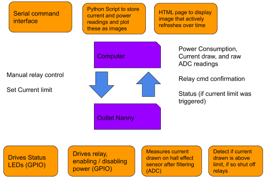
Our device required development on three fronts, the power path (which we nicknamed the Outlet box), the PIC32 code and peripheral circuitry for control, sampling and simple LED interface, and the computer scripts used to expand the project.
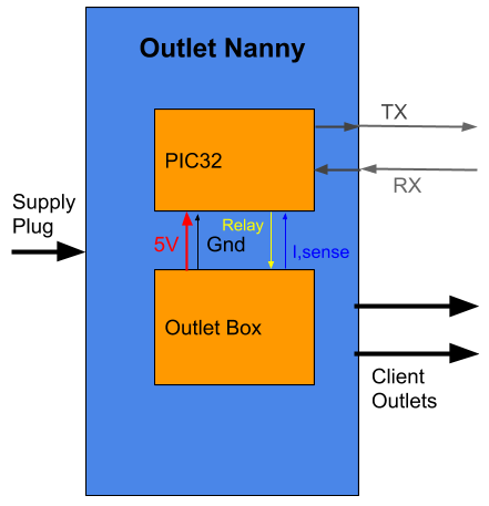
The outlet box is responsible for connecting the power path and providing the current sensor output needed for the PIC32 to process. The PIC32 then drives status LEDs to display basic details, measures current seen from the current sensor, provides a serial command interface for a device to request values / actions, and limits current if the measured value is greater than the set cap for an extended period of time. The onboard computer scripts initially turn on the relay, periodically request a current reading through serial, store this in a file, and plot the data over time.
We considered a few tradeoffs for hardware and software when developing the device. We had the intention of incorporating a Raspberry Pi into our project for website hosting and IoT, due to the wi-fi capabilities not working as expected and us running out of time on the project, we ended up dropping this feature. This worked in our favor in terms of our device efficiency since this would have consumed 0.5A of DC current on it’s own, making our device more wasteful to power the overhead. In addition, the 120V AC to 5V rectifier (which we nickname the “power brick”) in use was limited to 1A DC, putting us closer to being over budget for DC current consumption. In hindsight we realized a ESP8266 would have been a better fit for providing the needed connection to the internet and the use of a carbon neutral server such as Google Cloud to provide the web gui to interact with the device remotely.
The other major consideration was the maximum rating of current we wanted our device to be capable of measuring. Considering we wanted to make a discrete device that would fit in a 2 Gang Outlet box and reaching out to Bruce, we decided a max (AC) current rating of 5A would be appropriate. Had we had a greater amount of time to develop the product, we would have made a Computer Aided Design of the mechanical structure to get everything much more compact and developed a PCB for convenient connections for (both the power path and PIC32). Our current sensor wasn’t too sensitive (100mV/A) or had that high of a rating (+/- 20A), but it came at a lower cost for that reason, and most devices in lab were within the limit of sufficiently accurate results.
To measure the current sensor output, we sampled from our ADC at a regular interval and computed the peak to peak seen. We could have used FFT to give us a greater idea of not only the current at the line frequency, but harmonics produced by the device. Although this would have been handy for determining device power factor, which could be used to determine theoretical efficiency, we used sampling for the ADC readings because it was simpler to implement and required much less computation. In addition, we considered plotting the data through the PIC32 on a TFT instead of using a web app interface but decided to push for some kind of web app interface in case we could get the project to work with Wi-Fi.
Our device keeps the safety of the client in mind, following electrical regulations of the 2014 National Electrical Code within our judgement. The device is made such that accidental contact with the live AC line (120V RMS) is prevented. The Outlet box encloses all of the power path and only provides exposure to this through the client outlets and the supply plug, both of which if used properly should protect the user [110.27(A)]. We have our own lockout/tagout procedure for our device where if working on the Outlet box circuit, we place electrical tape on the supply plug to prevent accidental energization and we remove the front plate to access it’s contents. When done accessing the Outlet box circuit we placed the front plate back on and re-energize the device. Even though the front plate doesn’t fit the PVC box snuggly, we are able to screw in the plate to the switch and use electrical tape to reinforce the protruding portions to the box. We also maintain color convention for both practice and the US National Electrical code in our power path assigning black to primary (supply) hot, white to neutral, green to AC (Protective) Ground, and red for secondary (client) hot [AllAboutCircuits]. We pass the client ground and neutral connections on the client outlet from the supply side and pass the hot connection after the relay to client hot. Note that the electrical code states we cannot use neutral for more than one branch of the circuit unless “enters from a cable unique to the circuit that makes the grouping obvious” [200.4]. The last regulation we’ll talk about is on Outlet Device Ampere rating where our device must be able to manage a current not less than the load to be served [210.21]. Since we designed our Outlet box to not handle more than 5A I RMS of AC current and the box is designed to shut off the relay if such current or higher is pulled, our device meets this constraint assuming the user doesn’t set change the limit to be higher than the default. We allowed the user to change the limit greater than this for debugging and forgot to prevent this. Unfortunately, at a high enough load our current sensor output produces a voltage over our ADC reference forcing a microcontroller reset while giving the relay power! We mention a patch for this issue in the hardware section.
We realized as we were writing this report that there is a patent for a “power monitoring system” that is very similar to our project, receives power from a main supply line, offers that power conditionally to several client devices, and monitors there power consumption. In addition, they also use a microcontroller for all their data processing and control logic.
This patent document also includes this statement:
“Depending on the nature of the functional state of the device and the nature of the other electrical devices, the supply of power to any or all of the other electrical devices can be shut off, so that not all electrical devices are powered in situations where power to them is unnecessary.”
This is one of the functions of our power monitor device, where a current limit can be placed where if that limit is surpassed, the power relay is shut off.
Not only that, but related to our user interface (UART):
“the invention provides a user interface for use with . . . means for receiving data output from the monitoring device relating to the monitored power output; signalling means for sending a signal in response to the received data; and control means for communicating with the monitoring device to effect a change in power consumption of at least one of the electrical devices”
The patent linked, however, is a patent for a wired device using broad language in terms of control, communication, and distribution making it easier for our product to be included. While our original project idea was to have a wireless IoT power monitor, we ran into issues getting to finish the web portion of our project. Fortunately the patent expired in the US on December 16th, 2019.
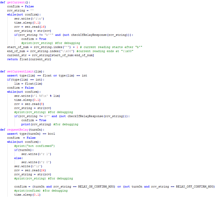
Our user-interface is controlled by a Python script named sera.py that reads the user’s inputs into a console, and can return useful information to the user when giving a command, such as entering 'r' to request the status of the relay, printing the current reading in a readable manner, and giving feedback of the results of entering a command like setting the current limit.
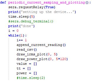
We can plot the current values given by getCurrent() by using serial_and_pyplot.py—it appends the values to a CSV file, along with the time they were read, automatically. It also reads the CSV file and graphs a figure including every point, showing the value of the current with respect to time. This figure is saved as an image, and is able to be seen on an HTML webpage which automatically refreshes every 5 seconds, so that we can see the changes the current sensor has detected in the past 5 seconds.
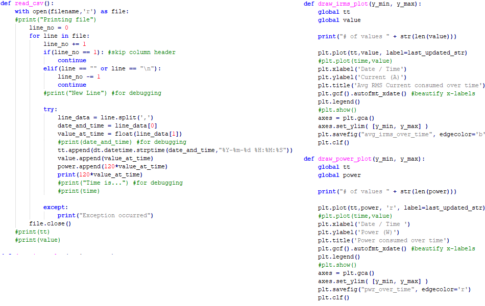
We also graph power usage as a function of time, using the same values of the current readings, but multiplied by 120.
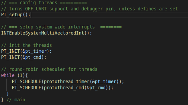
We implemented our PIC32 code for the Outlet Nanny using a timer interrupt, a timer thread, a command thread, and child UART threads to send/receive. The main function initializes our setup and does round robin scheduling between the timer and command thread using a while loop. The threads are implemented with protothreads.
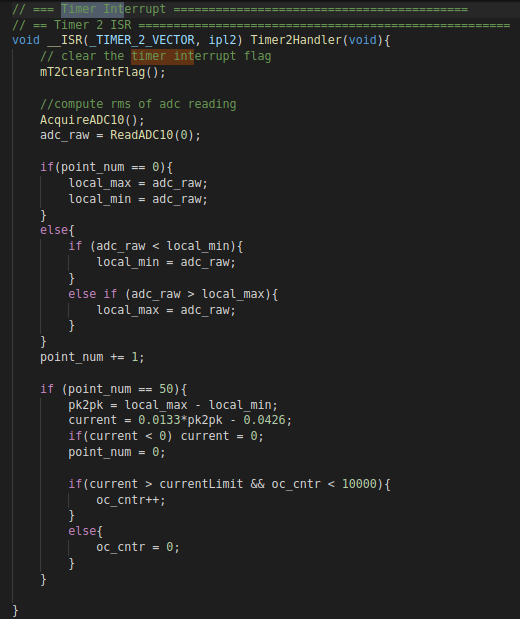
We sampled at regular intervals of 3 kHz, 50 times the line frequency of 60 Hz, to get instantaneous current readings. To compute the peak to peak (pk2pk) current sensor output seen on the ADC, we would store a local maximum/minimum per period and overwrite this once a new max / min was seen. Once the period had finished, point_num is 50, we took the difference to get the peak to peak signal seen in terms of 10 bit ADC reading, then we cleared the local max / min. We would then determine the current empirically. Through several devices with fixed power ratings and a 120V RMS ac line, we estimated the expected RMS current and used a line of best fit with Google Sheets to determine how to translate a peak to peak ADC to RMS current. The current sensor is expected to deviate from it’s 2.5V bias by the one tenth of the current flowing through the device. With the transfer function seen after the low pass filter, the 10 bit ADC that uses 3.3V as reference, and the assumption that the current is a 60Hz pure sinusoid, you get the equation below. Our experimentally determined equation is very similar and the slight difference may be due to the power brick’s voltage ripple.

We then reset our interrupt counter, preparing for a new period of current sensor data to poll. Lastly, once the RMS current seen by the sensor is computed we check if this is above the limit specified by the user with the ‘l’ command, if so increment the overcurrent counter, oc_cntr, by one, otherwise reset this counter to zero. This value is compared in our timer thread to determine if the device should switch to current protection mode.
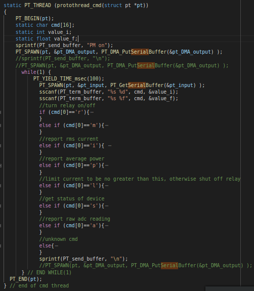
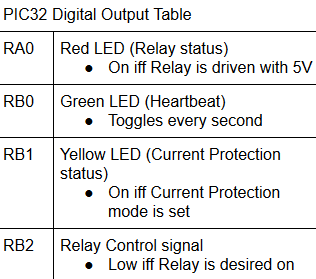
A thread is used to manage UART Serial communication so the microcontroller appears as a command interface when interacting with it through PuTTY. We prompt the user the device is on and continually take in their input with PT_GetSerialBuffer, use sscanf to parse command arguments from the char array, and use PT_DMA_PutSerialBuffer to transmit a response, similar to Serial_1_2_3_test_all.c and Lab 3, however our code is a little less efficient and instead of using case statements we use if/else conditionals. The user can enter up to 16 characters per command, where the first letter is the command type and the character following this and a space character are the input argument, and terminate the command by pressing the enter/return key. One command is the user manually setting/clearing the relay, they can control it if the device isn’t in current protection mode, if so a nonzero input turns on the relay by clearing the relay control signal on the PIC32. Note that a Red LED is set and cleared the complement of the PIC32 control signal to display that the Relay is on, providing power to the client outlet sockets. A zero input sets the control signal, disabling the relay. Then a confirmation message is sent. If the device is in current protection mode, the relay control signal isn’t adjusted and the user is prompted the device is current limited. In addition other commands are:
We use the human readable variant of the GetSerialBuffer child thread with a modification, when interacting exclusively with a human, we use the Protothreads header as is and each character received is sent back for user feedback. However once we wanted our python scripts for the computer to parse the serial response, we decided to comment out the portion of UART that sends all characters received. The machine buffer also offers this but requires more work to do so and doesn’t yield waiting for the user to input a new character but yields based on whether a DMA transfer is done. With humans typing relatively slow to the UART data transaction, we get better CPU Utilization using the human readable pthread. Even when our computer is interacting with the device via python script since we would want to send our commands only so often. To make this change we only need to vary GetSerialBuffer in pt_cornell_1_3_2.h.
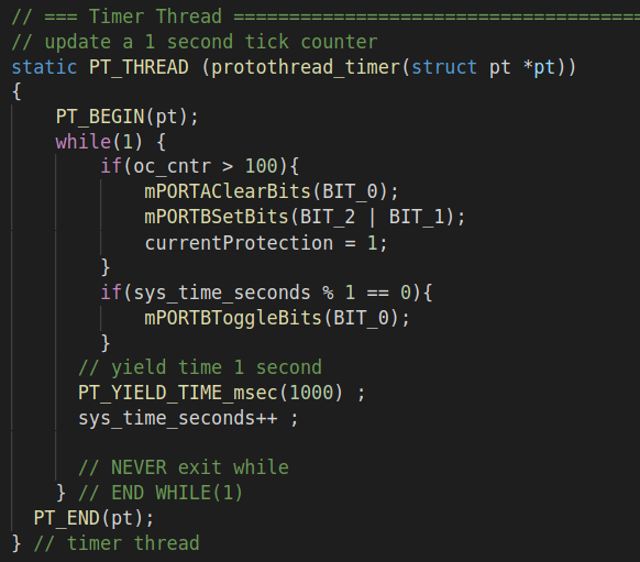
A timer thread is used to toggle a heartbeat LED and check if the device over current counter is over 100, which means for over 1.6 seconds the RMS current is greater than the limit. Under this condition, the current protection LED is set, and the relay (with it’s LED) is shut off, cutting off client power outlet sockets. The reason why we check if we pulled our current limit for a set amount of time in the timer thread was to guarantee the device cannot enter current protection mode in less than a second of duration with the thread acting as a buffer since this thread can only execute once a second and the timer oc_cntr is required to be greater than 100. Since the counter can only increment at 60Hz, the first execution of the timer thread immediately after the oc_cntr is reset to zero can’t set off current protection mode.
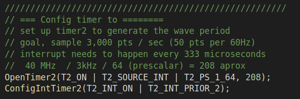
In our main function, we first disable analog inputs by clearing the analog select registers and then setup our ADC. We used an initial setup of our ADC similar to Bruce’s TFT_ADC_read.c. We use the 3.3V voltage rails with no auto sampling (meaning we need to acquire a sample before reading from our ADC), no offset calibrated, using half the system clock speed (20 MHz), using analog channel 11 (Pin RB13). We then configure a timer such that it occurs at a rate of 3 kHz (compromised to 3,004.8 Hz to use a larger prescaler from peripheral clock). Afterwards we declared our Digital outputs, as shown below.
We then enable interrupts and then begin initializing our two parent protothreads: timer and cmd. The child threads (for UART transmit/receive) do not have to be initialized here and are spawned as needed. Finally we execute the threads with a round-robin scheduler utilizing a while loop.
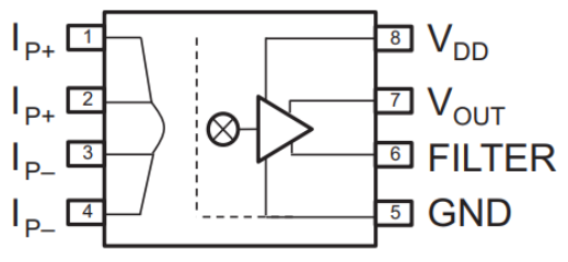
Our project relied on finding a feasible current sensor: given a current passing through or near the device, an output voltage proportional (or somewhat related) to this current is seen that wouldn’t bottleneck the desired RMS current of 5A or less. Furthermore, the voltage of the current being sensed would be 120 V RMS, with peak voltages near +/- 170 V, so isolation between the voltage output and the current sensor would be desirable. We looked at several devices but determined the ACHS7122 would fit our needs very well. The device requires the measured current to go through the device, entering on Pin 1 and 2 and exiting on Pin 3 and 4. Since current generates a magnetic field and with a Hall effect sensor it can measure a voltage across a Hall element due to a magnetic field, the ACHS7122 can measure the current passing through the device with great accuracy. The sensitivity of the device is 100mV/A and the zero current offset is halfway between Vdd and ground. An offset from ground is needed since the PIC32 will measure this through it’s ADC and our current setup requires the output voltage to be between ground and 3.3V. If the current through the device and it’s sensitivity attempts to produce an output voltage below ground or above it’s input voltage, it would saturate at its respective rail.
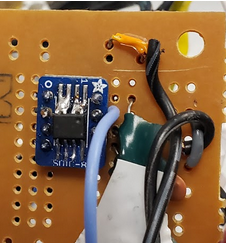
We populated the current sensor on an adapter board the course provided by Adafruit that made the SOIC footprint component compatible with solder boards and increased conduction for the current terminals. The image above shows the components placed on a small solder board without the hot wires in our power path soldered (would be connected to the left side). Under the tape is our two capacitors needed to set bandwidth and a bypass capacitor as the two are prone to shorting each other with how we placed them. We then tested the sensor on it’s own with 2 DC power supplies and a 4 ohm high-wattage resistor. We powered the current sensor with 5V and drove a separate 5V through the resistor load with the current sensor’s current terminals in series. We expected the current sensor output to be:
2.5V + (0.1V/A)(1.25A) = 2.625V
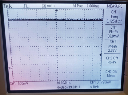
Through the oscilloscope when the load power supply was turned on we found the measured output was 2.62V, within 4% error.
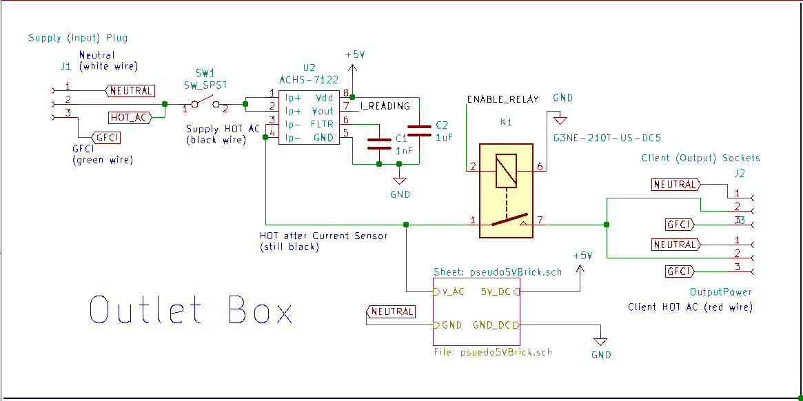
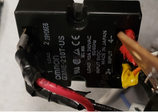
Once we confirmed our current sensor, we developed the outlet box with an incremental approach in mind while avoiding as many temporary connections as possible. We first needed to test the functionality of the relay Bruce provided us, the G3NE-210T-US-DC5, but didn’t want to risk accidental execution. For this reason we asked Bruce for an old power strip and removed it’s mechanical switch with our relay and confirmed whether we could control the relay to conduct if a 5V signal was provided on it’s input side. Note unlike the previous 4760 projects, this project required thick wiring to provide sufficient conduction for our power path. This prevented us from utilizing simple connection methods such as small jumpers and breadboards to connect & test our outlet box circuit. To connect a relay to the extension cord’s supply and client hot power while making it convenient to swap between the temporary extension cord and our future device, we used socket crimp connectors and 12 AWG wire with some soldering.
We confirmed this and then designed our Outlet box schematic. We first pictured the trivial case of an extension cord where the Neutral, Hot, and GFCI connections on our supply plug would be forwarded to the client sockets. We connected to the client socket via screw terminals on 12 AWG wires with the strands soldered together. We then added a mechanical switch that could control whether the entire device has power or not. We intended this as a safety precaution in case our device fails, we’d like to offer a quick way to (attempt to) disconnect the device from the AC line. Placing the switch any later in the power path would fail to disconnect the AC line for all other portions of the outlet box. We then passed the hot wire after our mechanical switch through our current sensor and then to the relay. We then connected the other load terminal of our relay to the hot terminal of the client outlets. Afterwards, we excluded the 5V power brick needed to convert the supply line to 5V DC (for our current sensor and PIC32), to first confirm the outlet box behaves like an extension cord, but along with a mechanical switch, there are relay wires which require a 5v input to turn on the client device’s power. We found the device passed this functionality.
Then we prepared the wiring needed to power the 5V power brick. We had to offer two more connections for our outlet box, one on the hot connection after our current sensor to our power brick, and neutral to power brick. The plug terminal used on the brick made it convenient to connect to with socket crimp connectors. We wanted our device to be able to measure its own power usage and current consumption so we wanted to make the power brick used to power our PIC32 and other 5V logic was in series with our current sensor.
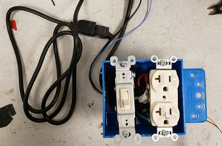
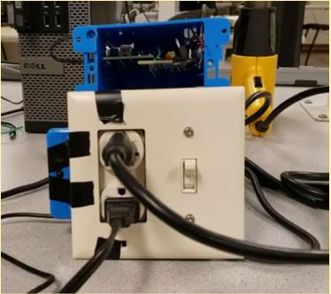
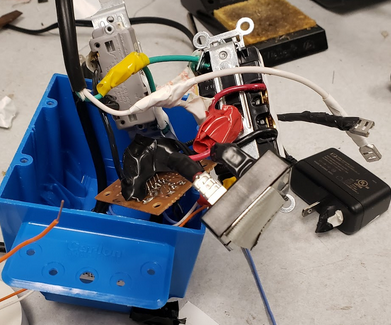
Keep in mind the above images are before our final pass of electrical tape applied to insulate connections and prevent shorts. When it was time to put everything into the PVC box, we had a frustrating time to get it all to fit. We underestimated the physical resistance to reroute 12 AWG wires. We placed the power. The final physical placement involved the power brick underneath the switch, the relay underneath the client sockets, and the current sensor a little below and next to the switch. Once we had the physical placement down we found the relay control lines, current sensor output, 5V, and ground all needed to be routed out of the box and convenient side drill holes would be desired. We made the holes and put the device back together again this time testing both control over the client power while measuring the current sensor output with an oscilloscope.
When our current sensor broke we attempted to develop our own AC current clamp as a replacement. The device would behave like a transformer and show a smaller but proportional current on the secondary winding proportional to the primary wire’s. We attempted this until we had to leave for thanksgiving break since we lost our spare components and wouldn’t get our replacements until after break. Unfortunately, this rushed attempt failed, most likely due to the lack of quality of the transformer we made, we salvaged an old core magnet and made about 80 windings by hand with some accidental overlap between every few turns.
Above is a recording of the Outlet box tested with a lamp, DC power supply, and oscilloscope.
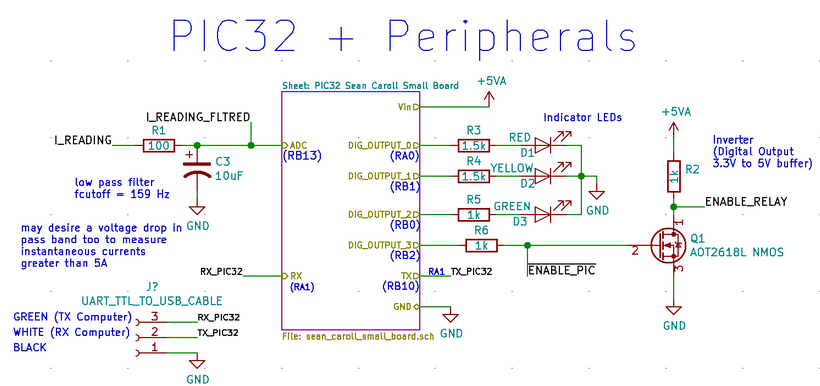
The last portion of our project we developed hardware for was the solder board & small PIC32 board used to put our PIC32 Peripheral circuitry together. This included the low pass filter on our current sensor readings, three status LEDs, UART communication lines, and an inverter to drive the relay with 5V or ground.
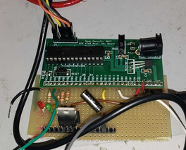
The above picture is the solder board for the PIC32 small board and peripheral circuits. We apologize that this is the only image we had of the board. We followed the instructions provided to populate the Small Sean Carroll PIC32 board and flashed code to toggle one of the LEDs per second to confirm it works.
We determined a low pass filter was desired since we wanted to pass 60 Hz current sensor readings while ignoring the higher frequency content. We also wanted to have a resistance of less than 1kOhm with our current ADC configuration. We ended up choosing a 100 ohm resistor & 10uF capacitor, giving us a cutoff frequency of 159 Hz. Note that because our pass band allows the current sensor output to pass through with nearly no voltage drop and our ADC configuration to use 3.3V and ground, we have an implicit maximum current limit of 8A. If a device pulls more current than this, the ADC will force the microcontroller to restart. We were unable to change this in time but we recommend a resistor in parallel with the low pass’s capacitor so the current sensor output is readable by the microcontroller for a greater range of load currents.
The inverter acts as a buffer so we can drive 5V on the relay through the PIC32’s 3.3V. This way the current needed to drive the relay isn’t driven from the PIC32 but the 5V supply line Vin. Vin is the voltage seen from the Small PIC32 board that’s on only if the small board’s switch is on. This prevents the relay from being turned on while the PIC32 is off.
Our UART sends a data point about once a second, and our web page containing the graph of the current readings as a function of time refreshes every five seconds. All commands sent through UART give virtually instant results. With a baudrate of 9,600 we can transmit 1,200 bytes per second assuming peak efficiency but our PIC32 code prevents a serial command from being processed within 100ms after the response of another command has been handled. For humans typing into a serial interface this is fine but for our PySerial scripts this delay is present in those scripts as well. Since there are no other threads that demand ASAP utilization of the processor, we could have made the yield time shorter on our microcontroller or make our threads pre-emptive and use this for UART but we decided not to since the delay in pySerial code isn’t significant.
Current limiting for a device that is consistently over it’s RMS limit takes about 1-2 seconds, responding fast enough to shut off client devices in case of accidental shorts or underestimated loads while forgiving client devices for any transient start up.
We did not measure the cycle duration of our interrupt or threads but none of these processes require quick or efficient computation. As such we took the lazy approach and did an expensive operation in our interrupt: multiplying a float. Assuming all other operations are negligible and using this source we believe it would take 736ns to compute this. Although expensive, it would only prevent interrupts executing at 1.35MHz or above from timely finishing before the next interrupt. However this does hurt our CPU utilization time so we could improve this by using fixed point and computing the RMS current with this.
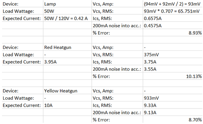
Our current readings were within about 11% of the expected results.The current sensor device itself has an error margin of 10%, so we think we’ve done a good job at keeping the error relatively low. We could slightly decrease the error on the PIC32 side by sampling at a faster rate, giving us more data points and less of a difference between our actual max/min and the one we were able to find through sampling but 50 data points per period seems to only increase the error by 1%.
None of our wires in our power path are exposed and are well-insulated, in the box or outside of it. We also maintained a tag-out/lock-out system to prevent accidental electrocution. We made sure every connection besides those connecting between the PIC32 and Outlet box were soldered well to avoid any open circuits. Our device also included a switch, which can turn off the device completely. Most of the wires used in this device are contained in a small PVC box that we screwed shut, so there’s absolutely no exposed wiring in our device that’s on the 120V line. Finally, there’s a default current limit set when the device is connected, which is 5A. If the current sensor reads any current value higher than this, it will turn off the relay.
Our device starts with ‘safe’ default settings (the relay is off, current limit is 5A) for first-time users. When giving a command in the serial console, the result of the command is echoed back to the user, so that they can see if their command went through, and what the result of it was. However if the device pulls a significant amount of current, 10A or more, the Microcontroller will reset due to the ADC, the relay will remain on, and the client device will remain powered until our power path devices rated at 5A fails. This is a quick issue to patch as mentioned in the hardware section, either adjust the ADC voltage reference and/or adjust the filter between the current sensor and the ADC. This issue also caused weird characters to be printed on the serial interface. The only way someone could hurt themselves using this device (outside of the high load issue) is by either breaking it open and ripping the insulation off, or sticking a piece of metal into the electrical outlets.
The Serial command interface is pretty limiting on who could use our device but at the same time python scripts could automate most of the commands given to the device and only require initial setup. Often we found ourselves debugging why the client devices weren’t receiving any power and realized we forgot something such as flipping the switch, connecting the relay wires to the inverter, or plugging in the Outlet Nanny itself. The status LEDs were a huge help to gauge what had power.
During the project, we were worried about the accuracy of our current readings, and once we tested them, we ended up seeing that our accuracy was very close to the accuracy margin of the current sensor itself—11% vs 10%.
When we started this project, we expected Raspberry Pi implementation to not be the most difficult part, but for reasons we don’t really understand, our Raspberry Pi Zero couldn’t work with Cornell’s wi-fi. Because of this, we switched to a Raspberry Pi 3 pretty late into our project and despite attempts to provide some wireless connection to the internet, including an AWS server that would act as a middleman between the client’s web browser and the raspberry pi, we were unable to setup a wireless connection in time that we could develop with. Had we not needed to remanufacture the Outlet box due to current sensor failure the saved time could have made the difference. In the end, our device must be wired to a computer to read the current values, which was not what we originally wanted.
We did expect the hardware work to be the most time-consuming part of our project, and that it was. As for hardware debugging, aside from needing to replace the current sensor because our first one was fried, we hit our goal.
We could improve our device on three fronts, remote access, improved data processing, and fixing the current sensing flaw if under high load.
Our project intended to have Wi-fi connectivity so a client could monitor and control their devices. To provide that we may be dropping any consideration of a Raspberry Pi and using a ESP8226 Module, as well as make our web GUI look much more appealing, and be able to control the device without typing into a console. We haven’t looked into this alternative too much but would save us in terms of device overhead power consumption but would rely on PIC32 code to connect us to a server and a server to connect to such as Google Cloud. In hindsight we realized that the Pi Zero W uses WLAN which requires another device with WLAN and internet to connect the raspberry pi to the internet while the Pi 3 can connect to the internet via Wi-Fi or Ethernet but dissipates so much power.
FFT could also be considered so we could not only measure the current sensor at the line’s fundamental frequency but it’s harmonics too to determine the client device(s)’s power factor and reporting back it’s maximum possible efficiency. The only additional hardware change needed would require an isolated voltage sensor. This feature would require a lot more data processing and computation on our PIC32 for better accuracy and improved functionality.
The last feature change would be to account for high load device current draw and to be able to handle the full sweep of the current sensor’s output on our PIC32 ADC. The easiest and quickest fix is to place a resistor in parrallel with the low pass’s capacitor to have a voltage divider for our pass through frequencies but we’d need to readjust our equation to adjust an ADC reading to an RMS current. This is the least costly to readjust.
We based our code for UART communication off of Bruce’s given code for Lab 3, and we also used his Protothreads interface. Our Python UART-read code was based off of simple examples and documentation given for the library “PySerial”, and the same for the Python library “Matplotlib”.
No patent opportunities are foreseen for the project at this point.
The group approves this report for inclusion on the course website.
The group approves the video for inclusion on the course youtube channel.