Cornell University ECE4760
UART
serial
PIC32MX250F128B
Serial Communication
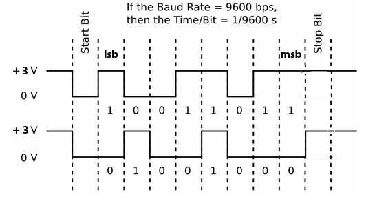
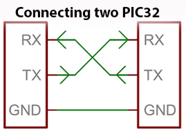
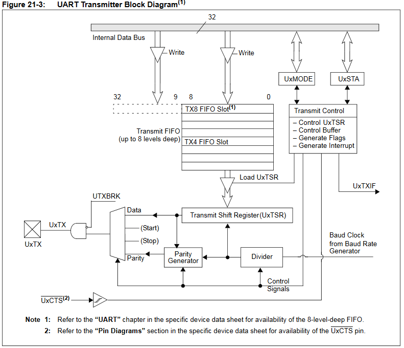
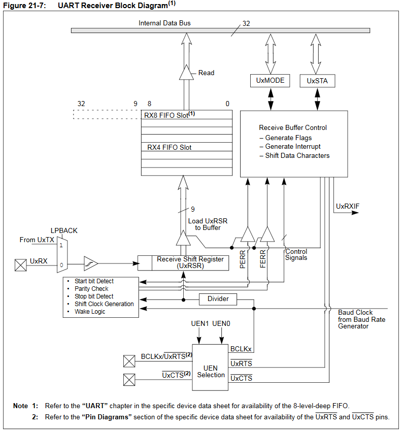
The UART is used for comunication of serial data. You can use it between two PIC32 processors, or from a PIC32 to a PC using a UART-USB COM port adaptor. It is even possible to use it in an address mode to communicate across several PIC32s. The UART supports TTL-level RS232, considered a legacy interface, but simple and useful. The UART transmit block diagram shows that there is a small FIFO buffer and a serializer. The serial bits are shown below. It takes 10 bit-times to send 8 bits. The UART receive block diagram shows a small FIFO and a de-serializer. The incoming waveform is sampled three times/bit for error detection. To connect two PIC32s, cross-wire TX and RX as shown below.
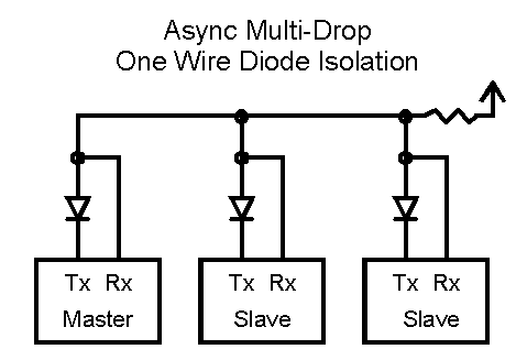
In addition to the standard 8-bit mode, there is a 9-bit address mode that allows several devices to share TTL-level UART signals. A typical multi-processor communication protoc ol differentiates between data bytes and address/control bytes. A common scheme is to use a 9th data bit to identify whether a data byte is address or data information. If the 9th bit is set, the data is processed as address or control information. If the 9th bit is cleared, the receiv ed data word is processed as data associated with the previous address/control byte. The protocol operates in the following sequence:
-- The master device transmits a data word with the 9th bit set. The data word contains the address of a slave device and is considered the address word.
-- All slave devices in the communication chain receive the address word and check the slave address value
-- The slave device that is specified by the address word receives and processes subsequent data bytes sent by the master device. All other slave devices discard subsequent data bytes until a new address word is received.
Connections for multiple devices might look like the following:
UART Error Handling
The UART will lock up if it receives a character with a framing error or overrun error. You must clear this in software using UART2ClearAllErrors(). The PLIB description gives the incorrect function call. The following code could be included in the Protothreads functions to read the UART (PT_GetSerialBuffer or PT_GetMachineBuffer).
To get the errors:
errorValue = UART1GetErrors();
if (errorValue & 0x01 )// Overflow error
if (errorValue & 0x02 ) // Frame error
if (errorValue & 0x04 ) // Parity error
To test and clear a frame error:
if(UART2GetErrors() & 0x02){
UART2ClearAllErrors();
PT_YIELD_TIME_msec(1); // may not be needed
break; // if in a while loop
}
UART to PC connection
On the PC side there will be a USB connection for serial communication between the running program and the PC, which will be running PuTTY. Set up PuTTY for baud-rate set in config_1_2_2.h (or after), no parity, 1 stop-bit, no flow-control. In the PuTTY config window, choose serial connection, then click serial in the left hand panel and set the parameters. Connect PuTTY to whatever serial port the USB connection configures. Use Control Panel...System...Hardware Tab...Device Manager Button...+Ports to find out which serial port is connected to the USB connection. If the PC does not autoload the required driver, then the COM port will not be attached or listed. Look for Prolific USB-to-serial Comm Port. If this happens then you will need to manually download the driver from Adafruit. You probably want the SiLabs Chipset driver CP210x, but check the device manager. It may be the Prolific Chipset PL2303. Mac OS versions are here.
UART to USB Adafruit serial cable:
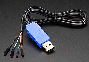
The blue serial-USB connection is a USB cable with embedded USB/serial bridge chip with 3.3 volt logic levels.
-- Use wires to connect the the three signals below.
-- Do NOT connect USB Vcc (red wire) to anything,
unless you need 5 volt power for a circuit not associated with the MCU.
-- Connect UART receive pin (U2RX) to the green wire (default to RA1 on big board)
-- Connect UART transmit pin (U2TX) to white wire (default to RB10 on big board)
-- Connect MCU ground to black wire
Standard Serial library for the UART
The standard serial library for GCC is <stdio.h>. All of the standard library routines are blocking, so don't use them in a threaded environment, unless speed of execution is more important than multasking. Instead use the ProtoThreads support explained below, and on the protothreads page. But for completeness, the standard i/o libary serial routines are outlined here.
In included in the library are routines to:
ProtoThreads Serial support
ProtoThreads 1_3_2 has support for using the UART communication to a PC serial terminal. The ProtoThreads 1_3_2 header assigns U2RX to RA1 and U2TX to RB10. The BAUD rate is set in config_1_3_2.h. The header also defines non-blocking transmit and receive routines for the UART. These routines are non-blocking DMA/polled transmit routines and non-blocking polled receive routines.
The UART serial interface is inherently slow, so for good multitasking, the string transmit and receive functions need to be able to yield to the scheduler. The transmit routines, PutSerialBuffer and PT_DMA_PutSerialBuffer can yield on a per-character basis or on a full string if the DMA transport routine is used. For all the details see the ProtoThreads page. An example code shows how to use the routines below. There are more examples on the Protoboard page.
PutSerialBuffer -- A thread which is spawned to send a string input from UART2. String to be sent is in char PT_send_buffer[max_chars]. If more than one thread can spawn this thread, then there must be semaphore protection. Control returns to the scheduler after every character is loaded to be sent. This thread returns to the parent thread after it sends the entire string. To use this, config_1_x_x.h must contain #define use_uart_serialchar PT_send_buffer[max_chars]. If more than one thread can spawn this thread, then there must be semaphore protection. Control returns to the scheduler immediately. This thread returns to the parent thread after it sends the entire string. To use this, config_1_x_x.h must contain #define use_uart_serialThere are two different receive routines. One assumes that a human is typing on a terminal, the other assumes that a machine (e.g. another PIC32, an Aduino, or GPS module) is sending information over the UART. A human expects to be able to see what they are typing, be able to erase characters, and always terminates a transaction with the <ENTER> key. None of those expectations are true for a machine connected to the serial input.
PT_GetMachineBuffer -- A thread which is spawned to get nonblocking string input from UART2. This function assumes that a machine is sending data and thus does not assume any particular termination condition and does not support backspace, or echo characters. You can specify termination method. A terminator character (PT_terminate_char), or a character count (PT_terminate_count), or a timeout (PT_terminate_time). A zero for any of the three disables that termination condition. String is returned in char PT_term_buffer[max_chars]. No string is returned if there is a timeout. If more than one thread can spawn this thread, then there must be semaphore protection. This thread returns to the parent thread after it receives an termination condition. To use this, config_1_x_x.h must contain #define use_uart_serial
The 1_3_2 version uses DMA channel zero transfer for higher speed.ProtoThreads support for two serial channels
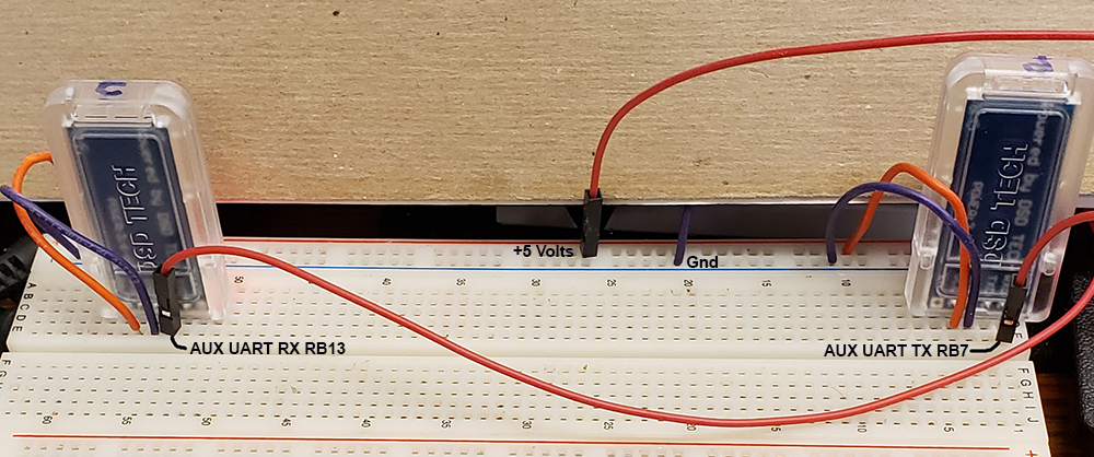
It is useful to have two UARTs available, for example if you want serial console control and to connect a Bluetooth serial module. Protothreads version 1_3_3 has the same console support as earlier versions, but has added an interface to UART1, called in the examples the AUX UART. The AUX interface supports only DMA send/receive and is thus not suitable for human interaction. It should be used for machine/machine communication only. Note that this example code will use all four DMA channels. The config_1_3_3 file now has serial enabling and baud rate setting for two UARTs.
The example code Has all the function of the 1_3_2 example on the Protothreads page, but adds two new commands to the serial command interpreter. The example assumes that UART2 is connected a PC serial console (typically PuTTY), and that the AUX UART1 TX line is connected to the AUX UART1 RX line.
• Wire RB13 (U1RX) to RB7 (U1TX) for AUX machine UART1 loopback. Runs up to 250000 baud.
• Wire RPA1 (U2RX) to USB TX line for console (as explained below)
• Wire RPB10 (U2TX) to USB RX line for console (as explained below)
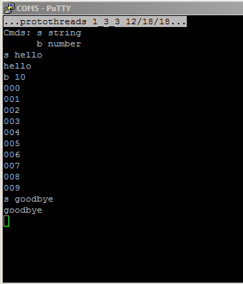
•• The s string command sends the string through the loopback on the AUX UART channel and prints it.
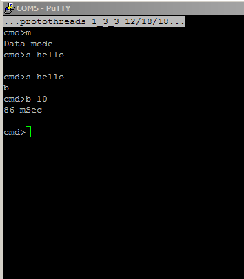
The loopback will timeout if the terminator character is missing. Default terminator is '#'. For example:
s 123# prints 123# after loopback. Sending s 123 prints AUX uart TimeOut
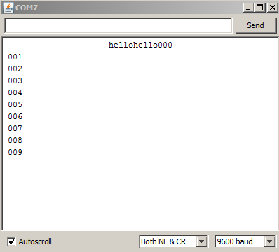
••The b number command sends a burst of number strings, each of which is the millisecond timer value.
For example b 5 prints
2707639#2707641#2707642#2707643#2707645# which is five timer values with their #-terminators. You can see that each transmission takes one or two milliseconds. The time to print eight characters at 115200 baud is about 690 microseconds. The time to loopback eight characters at 250000 baud is 320 microseconds. Total actual communication time is thus about 1 mSec. Total time for a transmission may include execution time of other threads, but you can expect about 1000 transmissions/sec for strings less than ten characters.
The code:
config_1_3_3.h, pt_cornell_1_3_3.h, loopback example, ZIP
Bluetooth communication -- Adafruit Bluefruit LE UART Friend --
Two UARTS, one to a Bluetooth module, and one to console
The Adafruit Bluefruit LE UART Friend module (part number 2479) is a BLE module with many functions (see product page), but I am using it here as a transparent, serial, BLE, endpoint. This means it can communicate with only one BLE master, which will probably be a cell phone or lapetop. It can accept a connection, but not initiate a connection. It is designed to use UART to communicate with an MCU and transmit the serial data to an app on a phone. The AUX UART code above was slightly adapted for the module. As before, assign U1RX to pin RPB13 (connect to TX on BLE module) and U1TX to pin RPB7 (connect to RX on BLE module). But the TERMINATION character in DMA send was changed to '\r' because the bluetooth module does not like a trailing NULL character. Most devices ignore a NULL, but this module does not. Be sure to ground the module CTS line (see page 12 of the datasheet).
To summarize PIC32 connections:
• PIC32 TX (UART1) to module RX
• PIC32 RX (UART1) to module TX
• 5 volts to module VIN
• Ground to module GND
• Ground to module CTS -- failure to ground this pin means that the module never uses its TX pin.
The example code keeps a DDS running at 100 KHz, runs the TFT display, and runs the keypad, but most of the interaction here will be via serial console using UART2. Wire RPA1 (U2RX) to USB TX line for console using a serial_USB cable. The serial commands are:
•• The m command toggles the Bluetooth module between command and data mode. In command mode you can type AT-style commands and the BLE module will return information. In command mode, the read LED blinks three times. In data mode it blinks twice.
•• The s string command actually sends commands or payload strings. For example in command mode, typing s ATI will return information about the BLE module. In data mode, the string will be sent to the module for transmission over BLE to a phone. If data is sent to the phone, then a string must be sent back from the phone app.
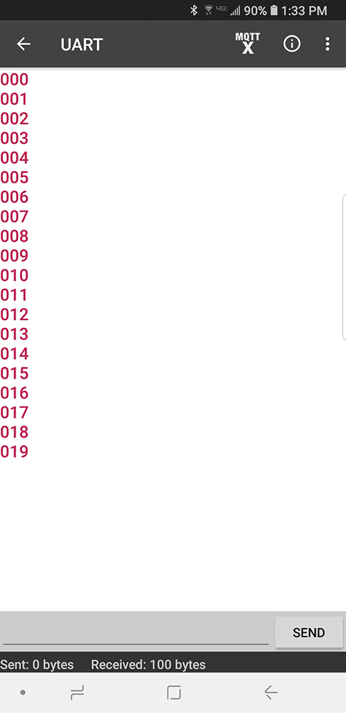
•• The b number command will send several data values as quickly as possible to the phone, without waiting for a response from the phone. For example b 10 will send the integers 000 to 009. The command also prints the time required to send all the values. It appears that the data link runs at full rate (1 character/mSec) at 9600 BAUD. Android screen dump of the command b 20 (putty dump). The Bluefruit Android app appears to find the module when Bluetooth is turned on and queries you for pairing.
(config_1_3_3.h, pt_cornell_1_3_3.h, Bluefruit example, ZIP)
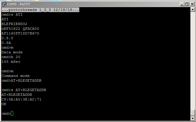
In command mode, you can change the baud rate using s AT+BAUDRATE={9600,19200,38400,115200} but the documentation says that you will drop characters above 9600. Sending burst of integers seemed to work at 19200 and 38400, but definitely does NOT work at 115200 baud. To get the BLE MAC address use AT+BLEGETADDR.
Bluetooth communication -- DSD TECH HM10 BLE -- (exact part source)
The HM10 BLE module can be configured as a peripheral or central module. A central module can initiate a connection. Once a connection is made, the HM10 modules act as a transparent serial link between two MCUs. The HM10 has a few quirks. It does not use (and cannot tolerate) an AT command terminated in any way (HM10 command summary). Therefore the AUX UART send function had to be modfied again to not use DMA, because DMA send is always terminated. No termination means that you cannot just type commands to the HM10. On the PC, you need to use a terminal emulator with a send function, such as the Arduino serial monitor. Start the Arduino IDE and click the serial icon in the upper right corner. The module command response is also not terminated and therefore prints all command responses on the same line of the Arduino serial monitor (ugly). On the PIC32 side, my PIC32 code handles the send correctly and also formats the module response.
There are a few steps to set up the HM10s for the example module configuration code below.
One HM10 is connected to the AUX UART on the PIC32. The other is connected via a serial-USB cable to a PC.
The steps to set up the data link between modules are summarized here (full description).
Note that once you set up the two modules, they will remember the settings and automatically form a data link.
PIC32 to HM10 connections:
• PIC32 TX (UART1) to module RXD
• PIC32 RX (UART1) to module TXD
• 5 volts to module Vcc -- Get the 5 volts from VIN on the SECABB (aasuming you are using a 5 volt wall-wart)
• Ground to module GND
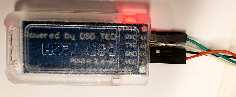
Serial cable (adafruit 954) to HM10 connections (picture):
• Cable green wire to module RXD
• Cable white wire to module TXD
• Cable red wire to module Vcc
• Cable black wire to module GND
The PIC32 example code, SECABB_HM10_1_3_3, keeps a DDS running at 100 KHz, runs the TFT display, and runs the keypad, but most of the interaction here will be via serial console using UART2. Wire RPA1 (U2RX) to USB TX line for console using a serial_USB cable. Screen shot of PIC32 console and Arduino monitor while paired for data. PIC32 console in module command mode after breaking link by turning off a module.
The serial commands are:
•• The m command toggles the serial interpreter between command and data mode. Command mode only works when the modules are not linked. You can type AT-style commands and the BLE module will return results of the command. If you are sending payload information, then put the interpreter into data mode. Cycling the power will put the BLE module back in command mode.
•• The s string command actually sends commands or payload strings. For example in command mode, typing s AT+RESET will reset the BLE module. In data mode, the string will be sent to the module for transmission over BLE to another module. If data is sent to another module, then a string must be sent back from the other module.
•• The b number command will send several data values as quickly as possible to the other module, without waiting for a response. For example b 10 will send the integers 000 to 009. The command also prints the time required to send all the values.
(config_1_3_3.h, pt_cornell_1_3_3.h, SECABB_HM10_1_3_3, ZIP)
The second example, SECABB_HM10_loopback, uses two modules hooked to the PIC32 AUX UART. One module has only its RXD connected to the PIC32 TX line, the other has TXD connected only to the PIC32 RX line. This forms a loopback through the radios. They MUST be pre-configured to link to each other as described in the previous example. Since this code is a template for data transmission between PIC32s, the send/receive threads have no handshaking because in general they will be on different MCUs. There is no command prompting because printing to the console must be very simple without handshaking.
Screen shot of commands.
•• The s string command sends payload strings. The modules are permanently nn data mode, so the string will be sent to the module for transmission over BLE to another module. The receive thread prints the payload.
•• The b number command will send several data values as quickly as possible to the other module.
For example b 10 will send the integers 000 to 009.
(config_1_3_3.h, pt_cornell_1_3_3.h, SECABB_HM10_loopback, ZIP)
Copyright Cornell University March 6, 2020