High-Level Design |
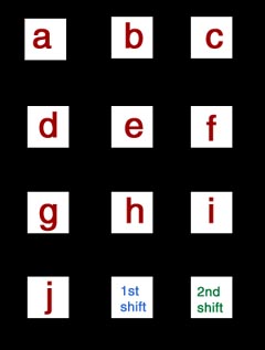
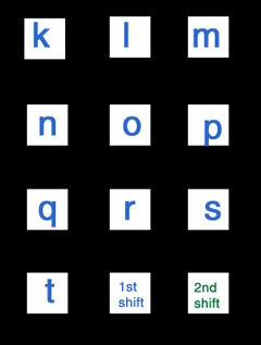
Before we began our design, there are some issues that we need to consider: 1) Materials Here is a list of materials we used: -2 Atmel 90s8515 microcontrollers. -2 STK200 boards. (One supply by ourselves) -2 4x20 LCD. (model Seiko L2014) -2 RF transmitters (TWS-434, from www.rentron.com) -2 RF receivers (RWS-434, from www.rentron.com) -2 pairs of holtek640/648L encoder/decoder chips (from www.rentron.com) 2) Handshaking One of the biggest issues is that we had to consider was the fact that all the RF components are operating at the same 433.92 MHz range. This means that a delicate handshaking scheme needs to be developed in order to ensure correct communication. It turns out there are many cases that need to be taken into account. For example, what to do when both transmitters are transmitting, when not to transmit, when not to receive. How to let the other device know what my device is doing, and so forth. Even though a full-duplex operation is not possible with these same frequency components, it is really not a problem since we are dealing with data exchange. Unlike voice communication, sending a message occurs much less frequently. And therefore the overall performance is acceptable even without full-duplex. (Please reference program design section for more detailed implementations of the handshaking process). 3) Hardware pin/port requirements Another issue is that we needed (per device) 8 pins for transmitter, 8 pins for receiver, 8 pins for LCD, 1 pin for Transmit Enable on the transmitter, and pins for the keypad input. However, since the Atmel 90s8515 mcu only support 4 ports = 32 pins, we had to sacrifice the 1 keypad pin (thus disabling 1 column). The consequence of this is that we had to use 2 shift keys to get as much keys as possible. Still, we were only able to get from 'a' to 'w' plus 'space', 'clear', and 'send' keys. Programming then gets more complicated because now when I charge and discharge PORTB to read in the keypad, I have to take the 1 less pin into effect. (Please refer to hardware design for the pinout of the circuit.) Here is the keymap for the key pad: 


|
Site developed by Johnny Tseng and Ajay Deonarine.