|
Digital Music Synthesizer |
ECE 476 Digital Systems Design using Microcontrollers - Spring 2002 Final Project
Jeff Ting jbt11@cornell.edu | Jinu Rhee jr65@cornell.edu
Click on above pictures to view larger version
Introduction | High-Level Design | Program/Hardware Design | Results | Future Considerations | Appendix
|
|
Introduction: |
Our ECE 476 Spring 2002 final project is a musical synthesizer that mimics the sounds produced by a piano and a clarinet. We wanted to create a device that could produce different musical signals by direct digital synthesis. Using Fourier analysis of the signals, we were able to imitate the sounds from different musical instruments. In addition, we wanted to give our keyboard users the ability to play multiple note chords to create more interesting music patterns. Working on this project gave us a lot of insight into the nature of sound and how high-end keyboard synthesizers actually operate.
Click on Picture Above for a Java Piano Synthesizer!
The best part about our project was that once we had finished debugging and assembled our final project, we were able to play simple melodies using our Digital Music Synthesizer. Some of these songs included simple tunes like 'Jingle Bells' as well as more complex tunes like 'Chop Sticks' which requires more than one note to be played at one time (chords).
|
|
High-Level Design: |
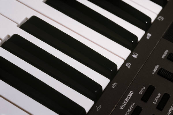
The range of the synthesizer covers from middle C (lowest note, C4) to an octave above middle C (highest note, C5) and includes all 11 notes in between including all the sharps and flats. This encompasses an entire octave on a musical scale. The sampling frequency of our synthesizer is 20 kHz which is many times the Nyquist frequency of our highest note (C5 523 Hz) so we avoid the possibility of aliasing. We stored the sine table values for each note into flash memory. Each value in the sine table is 6 bits in resolution. C4, at 262 Hz, has a period of 3.81 ms, so at a sampling rate of 20 kHz, we need 77 samples to represent a single C4 wave. A4, at 440 Hz, has a period of 2.27 ms, so we need 46 samples to create a single A4 wave. Since the period of each note is different and we are using a 20 kHz sample rate, each note has a sine table of a different size. Below is a picture of the piano keys (one full octave) that we implemented and a listing of their corresponding frequencies.
|
|
C4 = 262 Hz (middle C) |
|
|
C4# = 277 Hz |
|
|
D4 = 294 Hz |
|
|
D4# = 311 Hz |
|
|
E4 = 330 Hz |
|
|
F4 = 349 Hz |
|
|
F4# = 370 Hz |
|
|
G4 = 392 Hz |
|
|
G4# = 415 Hz |
|
|
A4 = 440 Hz |
|
|
A4# = 466 Hz |
|
|
B4 = 494 Hz |
|
|
C5 = 523 Hz |
Interrupt Service Routines (ISRs)
The range of the synthesizer covers from middle C (lowest note, C4) to an octave above middle C (highest note, C5) and includes all 11 notes in between including all the sharps and flats. This encompasses an entire octave on a musical scale. The sampling frequency of our synthesizer is 20 kHz which is many times the Nyquist frequency of our highest note (C5 523 Hz) so we avoid the possibility of aliasing. We stored the sine table values for each note into flash memory. Each value in the sine table is 6 bits in resolution. C4, at 262 Hz, has a period of 3.81 ms, so at a sampling rate of 20 kHz, we need 77 samples to represent a single C4 wave. A4, at 440 Hz, has a period of 2.27 ms, so we need 46 samples to create a single A4 wave. Since the period of each note is different and we are using a 20 kHz sample rate, each note has a sine table of a different size.
Our synthesizer was designed with the ability to play chords of 2 or 3 notes. Since a chord is just the superposition of multiple waves, this required the addition of different sine waves in order to play more than one note simultaneously. Since we used separate sine tables for each note with the same interrupt frequency, we simply added the values from 2 or 3 sine tables together inside the Timer 1 Clear On Compare Match Interrupt to create the chord. The reason for using a resolution of only 6 bits for each note is because the sum of a 3 note chord cannot exceed 8 bits since we are using PORTC as the output port.
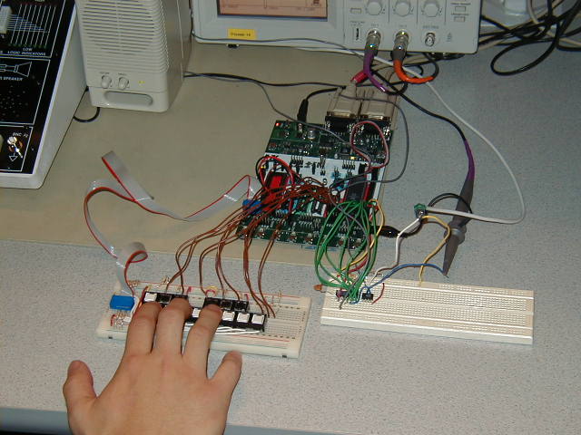
The duration of each note is dictated by the period of time in which the corresponding keypad button is depressed. So holding down a certain keypad button produces an extended note. We used Timer1 to create the music signal and Timer0 to detect button pushes from the keypads.
Fourier Coefficients
The sound of a piano is very similar to that of a simple sine wave so we did not use any Fourier coefficients to alter it. But in order to imitate the distinct sound of a clarinet, we did use the Fourier coefficients (which we found on the internet) to calculate the sinusoidal waveform and the sine table values. We represented the signal with about 10 upper harmonics. We used Matlab to calculate the different sine table values. The values were normalized and truncated to 6 bits to permit the addition of multiple waveforms when generating chords.
|
|
Program / Hardware Design:Software |
Our source code for this project consists of a mixture of C and Assembly. We used Assembly code in the Timer 1 Interrupt to generate the different wave forms and manipulate the chords. We used Matlab code to generate our different sine tables from the Fourier coefficients for the different instruments used by our synthesizer.
|
|
|
|
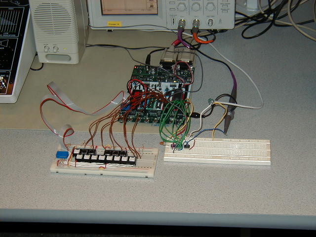
Hardware
We used the Atmel 90s8515 microcontroller chip on a STK500 board. We used 13 pushbuttons to emulate the piano keys so that each of the buttons represent a different note on the musical scale. The keypads connect to 2 ports on the STK500 board (PORTA and PORTB). We used the UART to interface with a hyperterminal on the PC in order for the user to select which instrument to use. The output signal is produced on PORTC and connected to an 8-bit Digital to Analog converter (DAC0808). The output of the D to A is fed through an op amp (LF353) and then sent to a speaker to produce the music signal.
|
|
|
|
|
|
|
|
Given the time allotted for our final project, we were able to successfully meet the goals that we had set out in our initial project proposal. Specifically, we achieved our primary goal to allow users to play chords of multiple notes (up to three buttons pressed simultaneously). Additionally, we were able to implement different instrument sounds by calculating their unique waveforms from their Fourier coefficients and thus instruments like the piano and clarinet could be emulated by the user through the use of the hyperterminal on the computer.
When the speaker output was measured using the oscilloscope, the measured frequencies closely matched the actual note frequencies as expected. As a result, a very clear, distinctive note was generated for each note in the scale from (C2 - C3). Even the three note chords generated a clear waveform that revealed the additive nature of its composition. The resulting chords were thus very clear and very pleasing to the ear.
Included below are some sample captures of the waveforms generated by our Digital Music Synthesizer.
|
|
|
|
|
|
Future Considerations:
|
|
|
Appendix:
|