![]()
![]()
We started by first building the input stage (amp and ADC) on a breadboard. Once we tested everything to be working the way it should by using the oscilloscope, we then proceeded to solder the input stage onto a perf board. The ADC used was the MAX1111 while we used the LM358 as an amplifier. We also removed 2 input jacks from Joel's dysfunational booster system and soldered it onto the breadboard. The input stage is shown below in figure 1. The circuit diagrams are shown in the appendix page. A variable resistor was placed into the feedback loop to control the gain.
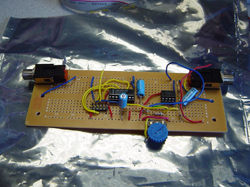
Figure 1 ADC input stage
We then proceeded to build the R-2R DAC as shown below in figure 3. Port D was used to send the output to the DAC stage while Port B was the SPI interface with the input stage. The LMC7111 amplifier was used in the output stage. One problem of using Port B for the SPI was that it was also the port which the board uses to program the chip so we had to disconnect Port B each time we wanted to program the board.
figure 3 R-2R DAC
A simple LCD circuit was made using a 16 character LCD screen connected to Port C. This LCD will display the status of the effects(on/off).
We started writing our program based on the schematics of the MAX1111 chip. We tried to manually create the clock and control signals but it did not work out. Then we decided to use the SPI interface (built in the chip) to control the MAX1111 chip which turned out to be much easier and efficient. After testing that the input from the ADC stage was correct, we proceeded to build the R-2R DAC so that we can see the output on the oscilloscope.
To add in the effects, we first used a button debounce state machine to poll the buttons. A button press will turn the effect on or off.
A statemachine was used to control the LCD screen. To display the effect on the screen once the button is pressed, we forced the state machine to go to that particular LCD state whenever the program detects a button press. At other times, the LCD will simply scroll through all the effects and display the status.
The various functions were written based on the mathematics shown in the Design page.
We had to zero the output of the device for the first 8 seconds to give the capacitors time to charge up. Without this, there would have been an irritating sound while the capacitors charged up. Also we had to use a software noise gate in order to block out some of the static.