Keypad Debouncing/Time-stamping
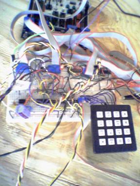
The user interfaces with the security system through a 16 button keypad and through a visual basic GUI. Central to the firmware design is the keypad button debounce mechanism. Button presses from the keypad are read once every occurrence of beatFlag (nominally 20ms) in from PORTC using the bidirectional pin approach:
//get lower nibble
DDRC = 0x0f;
PORTC = 0xf0;
delay_us(5);
key = PINC;
//get upper nibble
DDRC = 0xf0;
PORTC = 0x0f;
delay_us(5);
key = key | PINC;
This technique feeds in the contents of the keypad four bits at a time and stores the value in variable key . Finally, a lookup table is scanned to determine which number on the keypad, key represents. The number, 0 16 is stored in butnum . In our implementation the buttons map the following way:
butnum |
Keypad Button |
0 |
No button pressed |
1-9 |
Digits 1 9 |
10 |
Digit 0 |
11 |
A |
12 |
B |
13 |
C |
14 |
D |
15 |
* |
16 |
# |
A simple algorithm to detect when a new key is pressed by detecting if the previous button press registered a butnum = 0 and the current button press is non-zero. If a new key is pressed, the global counter, beat is assigned to variable keyBeat . beat is updated every 20ms in the Timer0 overflow ISR. Therefore, whenever a new key is pressed, it gets tagged with the time of the occurrence (measured in quantities of 20ms). 20ms was chosen due to the reflex time of the human hand and repeatability of button presses being accurate to about 20ms (if you are really good). For debouncing, the new key's keyBeat is compared with the previous key's keyBeat (prevKeyBeat). If keyBeat prevKeyBeat is less than some minimum value, then the new key press is treated as invalid and the code continues as if the button press never happened. It turns out that with a rubber keypad as used in the demo, button bouncing is quite common and occurs over long periods of time. Therefore the minimum acceptable time difference between button keyBeat values was set to be 10 (or 200ms).
A valid button press is converted into an operation number, opnum , to be used in the state machine. The operation number is identical to the button number, butnum , and is used so that altering the contents of butnum in the button debounce algorithm does not affect the state machine behavior.
Security System State Machine

Disarm
The security system initializes in this mode. Here, the system is deactivated, i.e. if the sensors trigger, the alarm will not sound. If any sensor does trigger (by opening a window or crossing the path of the IR pair) then a zone fault will be reported to the GUI and the faulted sensor will be indicated. The camera will not respond to zone faults in this mode. In order to arm the alarm however, all the zone faults must be eliminated (shut the doors and windows before activating the alarm). Buttons, C and D can be used to scroll through the zone faults. If no faults exist the panel displays Ready. Scroll buttons A' and B' can be used to forward scroll to the Teach Code mode or backward scroll to the Teach Motor mode respectively. To activate the alarm, the user presses the combination *5'.
Teach Code
Upon entrance into the teach code state, a rhythm LED will begin to flash at 2Hz. The scroll buttons A' and B' can be pushed to immediately leave this state and go to the Teach Motor state or back to the Disarm state respectively. To begin teaching a new code, the enter button is pressed (#') and a flag, oldCode is set high. This flag indicates that you desire to set a new code and yet there presently an old code stored in the system. The user will not be able to change the disarm code unless the old code is first entered correctly.
The disarm code is stored in two vectors, one containing the four digits in the code, and the other containing the timestamps associated with each key press. The timestamps are in the form of a beat count where each beat is 20ms. So a timestamp of 10 would correspond to a button press 10X20ms or 200ms after the beat reset (D') is pressed.
To let the system know you are a valid user and thus can change the disarm code, if forces you to enter the present code and stores your attempt in temporary vectors, attempt_code and attempt_rhythm. To help the user get the correct timing when entering the disarm code, the 1Hz LED blinks synchronized with the beat counter. If the entries of attempt_code and attempt_rhythm are within tolerances of the actual code and rhythm, then the ability to make a new code will be granted by setting the flag oldCode low and the flag newCode high. Then, the button D' can be pressed again to reset the beat counter and the new four digit code can be entered. This process is summarized in the flow chart below.
Teach Motor
This state gives the user the opportunity to edit the sensor layout or add new sensors to the security system. It also displays for the user the current configuration of the sensors in the room. The horizontal scroll buttons A' and B' can once again be used to advance to the Disarm state or return to the Teach Code state respectively. The vertical scroll buttons, C' and D' can be used to scroll through the various sensors setup in the room (presently, the system allows for up to 9 sensors in a room). For each sensor the sensor type and the horizontal and vertical position in the room will be displayed (in angular rotation coordinates). If the enter button (#') is pressed while a sensor's information is displayed on the screen, the motors will slew the camera to that sensor location and the camera output can be seen in the preview window. To adjust the sensor location, keys 2','8','4','6' can be used for altitude and azimuth adjustments. When adjustments have been complete, the enter button (#') is pressed and the new location is stored.
Armed
To arm the system, the user enters *' followed by 5' in the Disarmed mode when the Ready message appears (no zone faults). Once in the armed mode, the only way to return to Disarmed is by entering the proper disarm code in the proper rhythm. Failure to do so within an allotted amount of time result in a violation and the alarm flag to raise. The other way to enter Violation mode is if any of the sensors are triggered.
Violations are enabled in the armed state. If a violation is detected in an external interrupt or in the ICP interrupt then the camera will slew to the breached zone and snap pictures and the time of breach will be noted. If a violation occurs due to a timeout error in disarming the alarm or failing to enter the proper combination after a user defined number of attempts, the camera will slew to the keypad and snap pictures. A violation causes the alarm flag will be raised and this would indicate sirens sounding and authorities notified. Additionally, the triggered vibration sensors get reset so that if the burglar moves about the room the camera can snap more pictures as other sensors are tripped.
Hardware Design
Sensors
Vibration
To detect very small vibrations, piezoelectric strips are used. They generate a voltage signal proportional to the flex of the strip. Their sensitivity is spec'd in V/g and can be increased if a small mass is permanently fixed to the edge of the strip. The challenge in dealing with these sensors is they have very little drive power and must be appropriately buffered. Additionally, these sensors give a bipolar voltage output centered around zero volts thereby necessitating providing a DC offset to avoid a dual supply.
For rapidly varying signal analog sensors such as the piezoelectric vibration strips customized Schmidtt Triggers are used to accomplish digitization (see Appendix E ). The choice for Schmidtt Triggers instead of just a simple voltage comparator circuit is the added benefit of the moving threshold value. For a single supply opamp, the Schmidtt Trigger equation is:
![]()
When the input voltage, V in which is connected to the negative terminal is lower than V thres + , the output voltage is at +5V. But when it goes greater than the positive threshold level, the output drops to 0V and the threshold level lowers to V thres -- . This makes it difficult for the signal to cause the op-amp to return to the +5V output state. To make a true analog latch so that the signal cannot possibly return to a 5V output after latching to a 0V output, the input voltage signal can be amplitude limited with diodes such that the lowest possible input voltage is above the V thres - level. The only way to reset the trigger is to apply a brief five volt pulse on the op-amp's non-inverting input (this is handled in the firmware by connecting PORTD lines to the non-inverting inputs of all the Schmidtt Triggers (one per vibration sensor). During normal operation, the PORTD lines are configured as inputs and do not greatly interfere with the analog circuitry. When the op-amp triggers however by falling low, the PORTD pins are changed to outputs and source five volts onto the node for a period of 100ms.
Since the IR receiver signal is slower varying than the vibration signal and less susceptible to noise (signal is only produced when there is something impeding the IR transmitter), digitization can be achieved with a single voltage comparator or just an op-amp with no feedback loop and a fixed threshold voltage.
Hall sensors are used commonly for window and door detectors. The hall sensor we used had Schmidtt Triggered outputs and were provided to us with a pullup resistor in place from the leftovers of the slotted car project from last year. The Hall sensors were coupled with small powerful Neodynium magnets and their output signals were wired directly to the inputs of a logic AND gate.
When any sensor signal triggers, the motor is commanded to slew the camera to the violated zone and to snap and store a picture. If the triggered sensor is a vibration sensor, then after the first sensor triggers and latches, all the vibration sensors are reset by pulses five volts on the positive input terminals of the Schmidtt Triggers to allow subsequent vibration triggers. After a vibration is detected, a second vibration violation cannot occur until a set amount of time has passed (stored in the assembler defined parameter, vibduration and set to 1 second). This prevents the same vibration causes violations on multiple sensor locations thus confusing the camera.
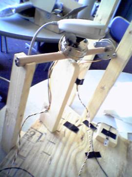
Stepper Motors
The motors used in this project were high torque 7.5 degree per step bipolar stepper motors. The motors are controlled using a repeating four step cycle of energizing the two inductor coils. Motor control was accomplished in the motor() routine in firmware. The motor routine takes the number of steps to move and the direction to move in (clockwise or counterclockwise) for the two positioning motors. Global variables, phaseH and phaseV keep track of which phase of the four step cycle was last executed. The next phase must be incremented by one if moving clockwise or decremented by one if counterclockwise making sure to loop 1 around to 4. The coil energizing patterns associated with each step are sent to the inputs of two bipolar motor driver chips (one per motor) which drive the motors using a separate, higher wattage supply. The stepper motors consume about 800mA each with is enough to make them and the power supply warm.
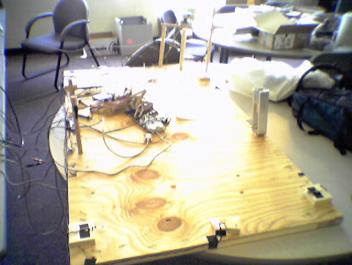
Demonstration Setup
A plywood demonstration room was constructed from the lid of a packaging crate that was discarded by those wasteful mechanical engineers in Upson Hall. Around the periphery of the board we placed seven sensors: 4 vibration sensors, 2 hall sensors, and an infrared emitter/receiver pair. In one corner of the board we mounted a camera on two motors, one for horizontal and the other for vertical control.
The vibration sensors were placed on the four corners of the board. Their placement was more a function the optimal location for determining the solution to the position equation discussed in the mathematical background section.
The two hall sensors are mounted to demonstrate the two typical ways these security sensors are used. The first sensor is mounted facing a pivoting block of wood that contains a magnet. This simulates the opening and closing of a door. The second sensor is placed facing a sliding block of wood. This simulates the opening and closing of a window.
The infrared emitting and receiving diodes are mounted raised off the board on two wooden dowels. IR pairs are used to protect short passageways in a room, they would be most effective if placed on either side of a window or doorway or across a narrow hallway.
User Interface
The user interfaces with the security system through a keypad and a Microsoft Visual Basic GUI. The GUI gives instructions and warnings to the user. It prompts the user for data that needs to be entered into the keypad and displays sensor information. It also maintains a running log of what activities have occurred and timestamps crucial events such as sensor violations and incorrect key code entries. Addtionally, the GUI gives a preview window of what the camera sees. When the system is armed and a sensor is triggered, the GUI displays the triggered sensor as a blinking red dot on a floor plan of the room (currently a wood demo board). It then captures a picture of the triggered sensor and stores it in a unique spot on the computers hard disk (indexed by time).
The GUI understands instructions from the keypad by interpreting ascii strings sent by the printf() function using the StrComp() VB method. Any action that elicits a response from the GUI display therefore must have a printf() statement that the GUI looks for and then can respond to.
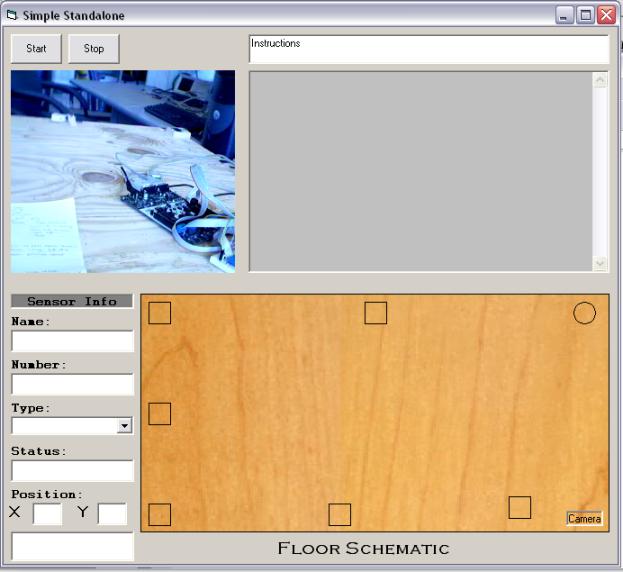
GUI Screenshot
Things Tried and Tried and Tried Again but Didn't Work
Determining the epicenter of a vibration on the plywood demo board was not meant to be. The assumptions discussed in the mathematical background section did not hold for plywood, and the result of this was that the timing between received vibrations was more a function of the vibration's amplitude than it was of its placement. It was very difficult to get to the point where we could actually receive timing data due to the complexities of capturing the very first received ripple off the vibration sensor. The actual raw data from the sensor had initial small amplitude wave fronts followed by a larger primary vibration wave. For accurate timing, all sensors would have to trigger on the same portion of the vibration waveform. First the primary vibration (with large amplitude) was chosen for triggering. But as it seemed the timing results were erratic for this portion, we modified the circuit to trigger on the initial small amplitude signal by giving the AC raw data waveform a gain of 101. Still the timing between sensor triggers could not be made constant for tapping at a fixed point on the board. We did see a degree of repeatability when tapping a fixed point on the board at a fixed amplitude but the force of a tap proved to be a very difficult thing to hold constant.
The positioning algorithm was simplified in the final version to not calculate the epicenter's coordinates but to determine which of the vibration sensors the epicenter was closest to and to slew the camera to that sensor's location. However, upon integrating all four of these sensors at once under the control of the MCU, one of the sensors did not function properly and seems to continuously be triggering. The malfunction seems like it may be related to the white board as the behavior is effected by pressing the underside of the board, however further evaluation of the board with an ohmmeter and different configurations found no evidence of this to be the case. Additionally, all four sensors work when using a bench supply and running independently from the firmware. After many hours of probing, the decision was made to disconnect the one problem sensor thereby leaving three functional vibration sensors in the demo board.
On the user interface end of things, we attempted to send directions to the MCU using the USART receive line. This became a much harder task than initially anticipated due to the failure of the MCU to want to take ascii sent from visual basic. Given another week (very full week) this feature would have been added.
On the camera control side, we originally coded the control in MATLAB using the image acquisition and image processing toolboxes but we were unable to have MATLAB generate a stand-alone application that wouldn't require these toolboxes on the lab machines (which don't even have MATLAB on them). Instead, we decided to go the Visual Basic route and use the Imaging Source demo code.