Digital Guitar Tuner
Eric Tai | Daniel Tsui
ECE 476: Spring 2005
Introduction | High Level Design | Program/Hardware Design | Results | Conclusions | Appendix
Program/Hardware Design
Software
The program was based upon the execution of time-based interrupts, which occurred every 10e-4s, or 0.1ms. We originally tried to push a much faster timebase, but it proved to be more problematic than helpful. There were two main subroutines that were being called: pollbuttons() and dosignal(). The program’s functionality can be broken down into several parts: the analog-digital converter, the period measurement and digital filter, and the input/output communication.
Analog-Digital
Converter:
The ADC was set up almost identically as it was in the examples during lecture. An analog waveform would be fed into the Port A.0 input and from that, the signal would be sampled into a digital bit stream of numbers ranging from 0 to 255. With VRef being set at 5V and an incoming DC Bias of 2.5V, this ensured that the digital signal would be using the full 0 to 255 number range, with 127 corresponding approximately to the DC bias. The function dosignal(), which samples and processes the signal, was run every 0.2ms which is equivalent to a sampling frequency of 5kHz.
Period Measurement and Digital Filter:
Frequency measurement was done by counting the time elapsed for twenty periods of the signal, and then comparing that value against the time needed for a known frequency to pass twenty periods. Timer0 was used as the counting time frame for this period measurement. Each period was detected by checking when the signal passed a set threshold. Twenty periods were measured when the signal crossed the threshold twenty times. The signal coming from a guitar string contains many overtones of higher harmonics that could also make the signal cross the set threshold. In order to count periods of the fundamental frequency of the string, a digital low-pass filter was used to cut out higher frequencies. This filter was implemented as an infinite impulse response (IIR) Butterworth filter of order 1. The filter coefficients were generated using the butter command in Matlab with a different cut-off point for each string. These coefficients are then used in the equation filtering equation: y=b*x+b*lastx+a*lasty. In this equation, y is the current sample of the filtered signal and x is the current sample unfiltered signal. Likewise, lasty refers to the previous sample of the filtered signal and lastx refers to the previous sample of the unfiltered signal.
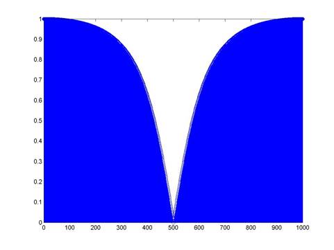
FFT of a 1st order Butterworth filter
Input/Output
Communication:
This device takes two inputs and puts out an output. The two inputs from the user are the waveform from the guitar, and a pushbutton indicating which string is being tuned. The one output is the LED indicating if the string is in-tune or not. An additional LCD is also used to confirm to the user what his/her inputs are.
Because a different low pass filter is needed for each string, an input of the string being tuned is needed. The string selection is driven by 6 pushbuttons, each labeled for a different string. Although not really necessary for this project, behind the pushbuttons is a debounce state machine that detects polls the input port every 50ms.
Hardware
There were a few analog components that were used in our design: the LED’s, the pushbuttons, the operational amplifier, and the LCD.
Light Emitting Diodes:
The use of the LED’s in our project was a visual indicator of how well the inputted frequency matched up with the actual frequency. There were a series of seven horizontally aligned lights, with six being red and the middle one yellow. If the yellow LED lit up, it meant that the input frequency was correct. If any of the left red LED’s lit up, it meant that the frequency was too low. If any of the right side red LED’s lit up, it meant that the frequency was too high. LED’s are driven by a current going across them. In order for us to use LED’s as a tuning indicator, we needed a resistor to drive the LED. A 75Ohm resistor was used to drive the current.
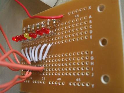
Picture: LED’s with resistors
Pushbuttons:
The purpose of the pushbuttons in our design was to allow the user to indicate which string is being tuned. Each pushbutton corresponded to a different string being tuned, which in turn changed the parameters for the Butterworth filter. Like the pushbuttons used in previous labs, these required a debounce state machine because when pressed, the signal would oscillate between a high and a low for a brief period of time.
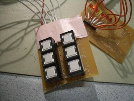
Picture: Pushbuttons
Operational Amplifier:
The circuit for our guitar tuner is actually not very hard to make. Since the guitar’s waveform has a peak-to-peak of near 400mV, we only needed to create a one-stage amplifier to get the signal into the range of the ADC.
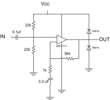
Figure: Operational Amplifier
The gain on an operational amplifier is measured by 1 + R2/R1. In the circuit above, R2 corresponds to 56kOhms and R1 corresponds to 1kOhm. In this case, our gain is around 57. The 0.1uF capacitor in the front serves as a filter for extraneous noise, allowing only frequencies to pass through. The 22kOhm resistors set the DC Bias at 2.5 volts for the ADC. The diodes are provided as a fail-safe protection for the circuit.
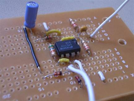
Picture: Operational Amplifier
Things we tried which
did not work
Hardware
There were not too many major problems with the hardware aspect of the project. There were a few situations where different elements (the LCD, and pushbuttons in particular) were not working, but in each case, it was due to faulty wiring, caused by long, overlapping wires. Testing of the circuit proved to be a tedious process, as we had to make manual adjustments to calibrate the tuner. Because there were overtones that caused problems in counting zero-crossings, the threshold point had to be adjusted for each individual string.
Another problem we encountered was the switch from running our circuit from the STK500 developmental board to our own prototype board. Because there was a switch in ARef that was not known to us, we could not figure out for a while why no numbers were being outputted. It wasn’t until we received a berating from Prof. Land that we realized there was a change in ARef.
Software
Originally, our plan was to have the software throw an interrupt every 1us, thereby making the guitar accurate to a time difference of 10^-6 seconds. However, for unknown reasons, the output from the ADC was nowhere near the expected value, so that idea was scrapped and a slower timebase was used. There were still issues with the numerical output, as the measured period for 20 cycles fluctuated a lot. Since this was not really a major problem, we did not try to fix it either.
There were many considerations that went into designing the digital filters. Originally the cutoff for each filter was set to be just greater than the fundamental frequency. While this managed to cut out nearly all overtones, it also had a severe magnitude effect that made the signal too attenuated to be useful. After some playing around with numbers, it was found that a cutoff just under the first overtone, that is nearly 1.9 times the fundamental frequency, would be sufficient to cut out overtones while keeping a useable magnitude. This filter still ran into some problems when the first overtone was extremely high in magnitude. This problem was resolved by adjusting the threshold where the period is counted and by allowing the plucked string of the guitar to propagate until the overtones diminished.