Software was written for two units. The majority of the software complexity resides in the main fan controller unit. In contrast, the remote control is rather simple with little more than a software debouncer for the push buttons.
The software design made use of a time based scheduler. The clock runs at 16MHz and timer2 was used to generate an interrupt once every 0.1ms. This acted as the heartbeat for the rest of the program. The interrupt routine did two things. It decreased the count down timers for individual tasks, and detected the tachometer signal pulse from the fans. Timer0 was setup with PWM operation for one of the fans, and the serial port was setup with non-blocking interrupt based transmit and receive. This ensured that other time critical functions such as adjusting the fan speed can proceed while the system was printing to the terminal.
The main program loop called each of the individual tasks when they are scheduled to run. In addition, the main program loop also took care of the status lights and alarm, as well as the starting and stopping of timer0 (for PWM mode) based on system parameters. The 6 scheduled tasks were: Outputting to the LCD, outputting to HyperTerminal, getting input from the keyboard, reading the temperature sensor, adjusting the fan speed, and pulse stretching for PWM.
Care was taken when coding the fan control system so that the program can easily be extended to support more than two fans. The #define MAXFAN parameter sets the number of fans in the system. Floating point variables typically begin with "fp", threshold variables are prefixed by "t_", and system flags are prefixed by "f_". This allowed the code to be more easily understood, minimizing debugging headaches.
Each fan and sensor pair's RPM and temperature reading is displayed on the LCD. Since the LCD is only 16x1 lines, we decided to alternately display the information from each pair. The LCD will first display the information from fan1 and then display the information from fan2 after a 2 second interval. The variable "lcddispnum" keeps track of the fan number the LCD display is currently showing.
The same information shown on the LCD is also displayed on the computer terminal. However, HyperTerminal will always display both fan speeds and both temperature readings simultaneously. It will also show the operation mode of the system (auto vs user, wireless vs computer). The screen is updated once every 2 seconds by first clearing the screen with a form feed command. For each fan, the computer terminal will also display the minimum threshold temperature at which point the fan will turn on and the maximum threshold temperature at which point the alarm will go off. It will also show a warning, "Fan fault detected!" if a fault is detected.
All commands were parsed based on a simple command line interface consisting of a letter followed by a number. The letter determines the functionality and the number provides the parameter to be used.
Since there is only one ADC unit on the MCU, in order to gather temperature information from multiple sensors, the ADMUX register had to be continually updated to read from different ports. This functionality resides in a scheduled task. Each time the function is called, it will read ADCH to get the temperature reading and setup the ADMUX register to read from the next sensor. The "sensornum" variable keeps track of the temperature sensor it is currently reading from.
The temperature sensors are calibrated for each MCU at room temperature. The initial room temperature voltage reading is defined by "inittemp" and the MCU's analog reference voltage is defined by "Arefvolt". By defining these parameters at room temperature, the sensor will be properly calibrated.
The fan speeds are adjusted periodically based on temperature from the temperature sensors. At the minimum temperature threshold, the fan is turned on. The fan speed will then ramp up linearly with increasing temperature, reaching full speed at 75% of the way between the min and max temperature thresholds. In the function, if "fanspeed" is 1.0, it indicates the fan should be spun at fullpower. The formula for calculating the fanspeed is:
fullspeedtemperature = (maxthreshold - minthreshold) * 0.75;
fanspeed = (current temperature - minthreshold) / fullspeedtemperature;
For PWM, the fan speed is controlled by varying the duty cycle of the PWM pulse. The PWM signal is sourced from timer0. A prescalar of 64 was used with fast PWM mode to generate a signal on OC0 at close to 1kHz. OC0 was set to clear on upcount and set on overflow if the PWM fan is on. To set the duty cycle of the fan, we would write different values into OCR0. This value is saved in "pwmspeed".
For the DAC, the fan speed is controlled with a value between 0 and 15 inclusively to the 4bit DAC input. This value is saved in "dacout".
The interrupt service routine detects the tachometer pulse by continually sampling each of the tachometer port pins. It records when the tach pulse is high and when it is low. On the falling edge of each pulse, it calculates the length of time the pulse spent in the low stage during the last period. This was used to calculate the RPM of the fan using the formula:
RPM = 600000/(input*divider);
where divider is a unique number for each fan indicating the number of pulses per revolution and input is the input waveform. This formula is derived from the observation that:
L(ms) = (60000ms/RPM)/(pulses per revolution)
where L is the period of each the tachometer pulse. Solving for RPM, we get the above RPM formula.
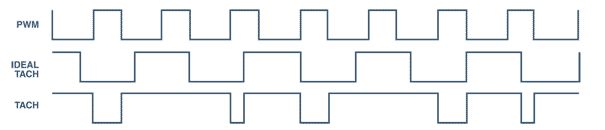
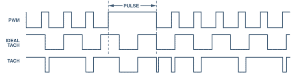
The tachometer only works when power is applied to the fan. With PWM the duty cycle causes the tach pulse to disappear when power isn't applied, which results in sporadic and unreliable tachometer output. To alleviate this problem, we use pulse stretching. Periodically, the PWM signal will use a 100% duty cycle for the purpose of getting a proper tachometer reading. The pulse is stretched for 3 full tach periods - enough time for stable detection of the RPM reading.
This is the biggest drawback of PWM. While it wins in hardware simplicity, the fan speed detection is not as accurate as the DAC fan. The pulse can only be stretched periodically which makes the RPM update rate slower. Furthermore, with slow speeds (eg, 10% duty cycle), pulse stretching to full power can noticeably affect the operation of the fan as it repeatedly spins up and down. A DAC fan provides constant power, making RPM detection simple.
The interrupt service routine also detects locked rotors when sensing the RPM. A fan fault is detected if one of the following occurs:
- The tach pulse stays high or low for more than 60 ms.
- The high pulse is more than 3 times longer than the low pulse for 5 consecutive periods.
- The low pulse is more than 3 times longer than the high pulse for 5 consecutive periods.
An alarm will light and sound when either of the temperature sensors exceeds their maximum threshold temperature or when a fan failure is detected. This check is done in the main program loop. If the alarm is to be turned on, the "f_alarmsound" flag is set. In the main interrupt service routine, if the above flag was set, it will toggle the alarm port pin. This creates a square wave with a period of 0.2 ms. This square wave drives a piezoelectric buzzer that creates a high pitched beep.
Serial I/O to and from the serial port and from the wireless remote control was done with a non-blocking method. When data is received, the receive interrupt is called, and the data is put into r_buffer one character at a time. When a whole command string is detected, this data is read out with gets_int(). Data to be transmitted is put in the t_buffer and sent using puts_int(). When the transmitter is ready, it will send the contents of t_buffer one character at a time. This method ensures that I/O will not block the operation of other scheduled tasks.
There are two sets of operation modes: Auto vs user, and wireless vs computer. In auto mode, the PWM duty cycle is continually updated with the "pwmspeed" variable, and the DAC value is continually updated with the "dacout" variable. In user mode, the PWM speed signal is driven high continuously to turn the fan on, and the DAC fans are sent the enable signal. This allows both fans to operate and to be controlled by the user adjustable potentiometer.
Since the MCU can only receive serial data from one source at a time, a physical switch will be used to switch between wireless and computer mode. The mux control signal is set based on the input of the switch. The software maintains transmission to the terminal at all times.
Wireless information was received using the receive interrupt. All wireless data packets are encased by a start packet and a stop packet. The MCU will only use the data packet if the start and stop packets are detected. This prevents the system from picking up random noise and transmissions from other remote controllers. The start, data, and stop packets are DC balanced so the receiver can maintain proper gain levels. Since only 5 different buttons are on the remote transmitter, the data packets were simply hardcoded as 5 unique bytes. RF transmission was done at 4800 baud to increase reliability.
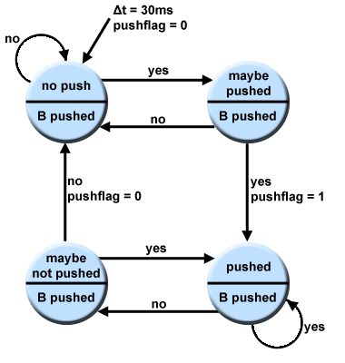
The remote control consists of five buttons. Four are for setting the minimum threshold temperature and one is for toggling between auto and user mode. The software uses a button debouncing state machine to read button presses into the 'inbutton' variable. This variable is checked and based on the button that is pressed, it will transmit it over the RF link. Input is only valid if only one buttons is pressed.
Transmission is done by first sending 15 bytes of 0xaa. This creates a DC balanced signal that the receiver can hone onto. Next 0xff followed by 0x00 are sent. This syncs the receiver so that the stop bit is detected and it is ready for the transmission packets. RF transmission was done at 4800 baud to increase reliability.
