ECE 476: Design with Microcontrollers
Final Project
AUTONOMOUS BLIMP
Benjamin Z. Tang (bt48)
Rishi S. Ramchand (rsr32)
CONTENTS
Introduction
Sound bite
We designed a lightweight circuit to autonomously steer a helium-filled blimp, avoiding obstacles in its path.
Overview
Our project controls a propeller-driven toy blimp; it keeps the blimp moving in a straight line if its path is clear, and otherwise navigates it around obstacles in its path. To accomplish the former task, our circuit uses a gyroscope to detect horizontal rotation and compensates for it by adjusting the propeller speed. Obstacle detection is performed using a digital infrared proximity sensor. The central challenge of our project was to build a circuit that was sufficiently light to be carried onboard the blimp, subject of course to the constraints of budget.
High Level Design
Rationale and Sources of Ideas
Our motivation for choosing this project stems for our shared passion for aviation. We agreed at the outset that we wanted an airborne project. Using the microcontroller for some form of autonomous control suggested itself naturally. Furthermore, accomplishing this would require the analog-digital converter (ADC), pulse-width modulation (PWM), as well as sensors and motors, and therefore incorporate elements from throughout the duration of the course. We also had a strong desire, however, to accomplish this project with everything onboard, and to have our aircraft fly independently of tether cables to supply power, since to the best of our knowledge, no final project has previously accomplished this.
Block Diagram
Figure 1. Top-level Diagram
Background Math
The volume of the blimp is 4ft3, or about 0.113m3. Helium has a lifting power of approximately 1kg/m3, and hence our blimp had an estimated payload of about 113g. As it turned out the actual maximum payload was about 90-110g, depending on the temperature and how recently the blimp had been refilled.
The motors each draw up to 150mA at full duty cycle for a total of 300mA. The MCU draws about 40mA, while the IR and gyroscope together draw about 30mA, putting our total typical current load (at 86% duty cycle) at about 350mA.
Hardware/Software Tradeoffs
Our largest tradeoffs were to accommodate the constraint of lift. We had initially proposed to mount sensors on the sides and base of the blimp as well, but these would have put the total weight of all components well above the payload of the blimp. Long wires running along the exterior of the blimp would also have added significantly to the weight.
We also initially planned to perform for IR detection with an IR LED coupled with an IR receiver. The IR receiver is tuned (by the manufacturer) to a particular frequency, and the MCU would turn the LED on and off at that frequency. The strength of the reflected signal from the receiver can then be used to measure distance. However, we opted to use a digital sensor instead that gave a high signal when no obstacle was detected, and a low signal when one was, as it is more resistant to noise.
Program/Hardware Design
Program Details
ADC
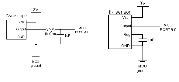
The ADC was used to read the filtered output of the gyroscope. The zero-rate output (ZRO) of the gyroscope with VCC at 3V was 1.57V and corresponds to a 10-bit ADC value of 535. We read and added ten values to effectively take the average of ten readings for our comparisons with the ZRO value. The relevant bypass capacitors were mounted on the custom PCB in the specified locations.
PWM
We used the two PWM signals from Timer 1 to control the speed of the micromotors via the optoisolator circuits by increasing or decreasing the duty cycle as appropriate. The signals had a frequency of 60Hz and the default duty cycle was set at 86% (OCR=220).
Navigation Algorithm
When the IR sensor does not detect an obstacle in its path, the MCU turns the fans with the appropriate duty cycle to drive the blimp in a straight line. We implement a binary feedback mechanism whereby the MCU reads the gyroscope and adjusts the PWM signals to compensate for any yaw. For instance, if the ADC value from the gyroscope indicates that the blimp is veering left, the MCU increases the PWM duty cycle to the left motor by 1bit and decreases the PWM duty cycle to the right motor by 1bit, checking first not to exceed the bounds of [0,255].
When an obstacle is detected, the blimp continues to move for 3 seconds and then the motors stop turning the propellers by setting both duty cycles to 0. The 3 second wait allows the blimp to get a little closer to the obstacle, to ensure that the latter does not disappear from view once the blimp begins to rotate away. The MCU then increases the duty cycle of the left motor by 5 bits at each interrupt, which causes the blimp to turn off to the right, and to continue to do so while the obstacle is in view. Once the obstacle disappears from view, the blimp resumes forward motion at the default PWM duty cycle. We realize that multiple sensors would have afforded a more complex navigation algorithm; we presented the skeleton of one such algorithm in our project proposal.
We considered storing 100 gyroscope ADC readings in array and filtering them to remove both high frequency noise resulting from the motor vibration as well as any possible low frequency drift, but neither of these was found to be sufficiently problematic since the gyroscope is mounted at the nose of the blimp far away from the motors, and we did not observe any perceivable drift over the duration of each blimp 'ride'. Furthermore, it was not necessary to know with accuracy the actual values of the ADC output. It was sufficient to know if the blimp was veering left or right, and then simply increase and decrease the duty cycle of the appropriate propellers slightly to compensate. We read the gyroscope and corrected the motors at 0.5s intervals, and therefore corrections were made sufficiently frequently that compared to the time delay of the movement of the blimp, our circuit would for all practical purposes be responding continuously.
Hardware Details
MCU
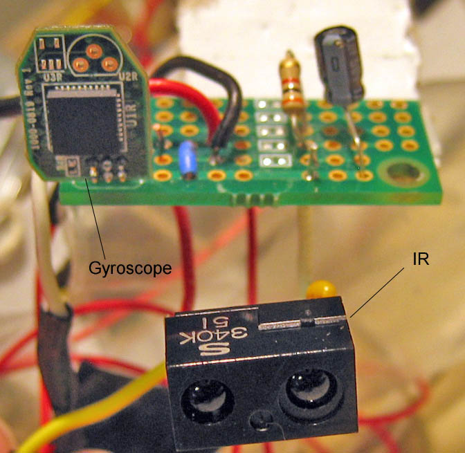
We mounted our ATMega32 on the custom ECE 476 PCB along with only the bare essential components: a 16MHz crystal, a programming header, the surface-mount capacitors and an on/off switch. The circuit was powered using a CR123A camera battery. We omitted the voltage regulator and connected the battery leads directly to Vcc and ground, since the battery voltage was 3V and well within the allowable range for our components. We then sawed off all the sections of the board that we did not need, such as the prototyping area and the area for the serial connector. We programmed our chip via the STK-500.
Sensors:
1. Gyroscope
We used an X-Y axis gyroscope, which was donated byHillcrest Labs. The gyroscope was read using the ADC and we measured only rotation around the vertical axis i.e. turning left or right. We filtered the output of the gyroscope using a hardware lowpass filter with a cutoff frequency of 1kHz, the recommended value to eliminate noise from the MEMS component in the gyroscope. We mounted the gyroscope and the filter on a FreeScale prototyping board, using only half the board and cutting off the other half.
2. Digital IR Proximity Sensor
We used a SHARP GP2Y0D340K digital infrared proximity sensor to detect obstacles. The sensor has a specified range of 60cm, though we were only able to get a range of 40cm. Its output is digital and active low: it outputs VCC when it does not detect an object, and 0 when it does.
Motor Control Circuits
We modified the optoisolator circuits in Lab 5 for our project. The BUZ73 transistors have a turn-on voltage of 3.4V, higher than the 3V we had initially planned to run the motors at. We replaced these with N3904 BJTs, which have a much lower turn-on voltage and are also slightly lighter.
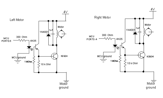
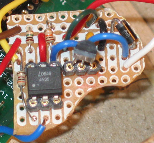
Figure 3. Optoisolator Circuit for Motor Control
Propulsion
We use two motors, a left motor and a right motor, mounted on the gondola on the underside of our blimp. We used were special high-RPM (approx. 20,000rpm) micromotors used to drive toy helicopter blades. Each draws about 130mA of current, which was supplied by a 4V Lithium-polymer battery.
Things That Did Not Work
Our first attempt was to perform the same type of navigation using a helicopter instead of a blimp. We purchased a second-hand radio-controlled helicopter, but we were unable to control it reliably even with the remote control. It was also far too light to lift even the custom PCB without any components. On the advice of our TA, we decided to use a blimp instead.
We also had to try out no less than 4 different kinds of batteries to power our circuit before finding one that could supply enough current but was also sufficiently light.
It also seems appropriate to mention in this section that the helicopter that was sold to us when we began work on the project was faulty and needed to be repaired, which we were actually able to do.
Results of the Design
Speed of execution
We were able to run the ADC at its full speed with no problems. We ran the PWM at 60Hz, however, since it was controlling DC motors. The blimp, meanwhile, is light and has a large surface area and therefore encounters significant drag. Its response time, therefore, was on the order of tenths of seconds to seconds.
Accuracy
We examined the PWM signals on the oscilloscope to see their response to the inputs from the gyroscope and IR sensor via our algorithm. They responded accurately and sensitively. The blimp did show some slight drift in flight, but this could as well have been due to environmental conditions e.g. airconditioning vents in lab. Otherwise, it was able to execute the required turns correctly.
Safety
Our blimp poses no significant safety concerns. The propeller blades are made of soft plastic and did not cause any injury even when our fingers got in the way. We inflated our balloon with helium, which is inert. The risk of it bursting as a result of being moved from the cold into a warm room was remote, but we considered it nonetheless. Further, our project did not interfere with anyone elses.
The helicopter we used initially did fly somewhat uncontrollably, and we were therefore careful never to fly it in the lab, and to hold it firmly while running the rotors in lab.
Usability
Our project, by virtue of its autonomy, is very easy to use. It requires only the flick of a switch and it flies on its own. Suspending and securing the gondola, however, is most easily done with the assistance of a second person.
Conclusions
Analysis and Evaluation
Our blimp performed its navigational tasks correctly and successfully avoided obstacles in its path. It flew untethered, and in these respects met the specifications we had laid out. We had not, however, anticipated the difficulty of putting a microcontroller circuit in the air, and we consider ourselves fortunate to have been able to do so. Our design incorporated the bare essentials, and even then, it was a Herculean task.
We were ultimately able to achieve our goal of keeping our circuit airborne by taking a very minimalist approach to designing and building our project. However, this was at the expense of many, many other things we would have like to do with our project. We have already mentioned that we would have liked to implement a more sophisticated navigation algorithm, with more sensors. We also toyed with the idea of communicating obstacle locations via RF to another ground-based MCU.
If we were to do this project again, we would (at the risk of exceeding the budget) use two blimps instead of one, to largely eliminate the constraint of weight, so that we could focus on working with the sensors etc. Nevertheless, it was satisfying to push the envelope with just one blimp.
Intellectual Property Considerations
Aside from code and circuits taken from lab descriptions, everything else in our project was original. The modifications we made to the optoisolators were our own ideas and we wrote the code ourselves. We did not run into any patent or trademark issues, and our parts were either purchased or donated and required no signing of documents of any sort.
Ethical considerations
We began with a bold plan to fly a helicopter autonomously using the Mega32. While we knew it would be difficult, we wanted to challenge ourselves and try to achieve something that others before us had failed to do. As we progressed, however, we were forced to accept the advice of our TAs and acknowledge that with what the limited resources we had, our initial goal was well out of reach. Although it disappointed us and meant that we had lost nearly a month, we put it down to experience and we are glad we gave it a fair shot.
On the other hand, we also on occassion offered suggestions, ideas, encouragement and help around the lab to other groups. We also did our part to keep the lab clean, cleaning up after ourselves at the soldering station etc. We were considerate of other users of the lab, and accommodated one group's discomfort due to our use of the Dremel tool by postponing that particular task.
By showing that it is possible, in spite of all the failed previous attempts, to build a project that is entirely airborne, we hope to inspire groups in the future to build on our work. We acknowledge the difficulty of overcoming the obstacles such a project presents, but we hope that in the future, particularly with improvements in battery technology, groups will be able to design airborne projects that are more sophisticated.
With regard to specific items of the IEEE Code of Ethics:
We avoided conflicts of interest.
We were to the best of our knowledge not dishonest in any way, nor did we accept or offer bribes of any form.
We were fair to all our classmates, TAs and the professor, giving no regard to of any form of demographic classification.
Legal considerations
A check with the website of the Federal Aviation Authority discovered no rules against flying an aircraft such as ours indoors.
Appendices
Code
A commented listing of the code is available here.
Cost Details
| Component | Cost($) |
Source |
|---|---|---|
| ATMega32 | 8 |
|
| Custom PCB | 5 |
|
| IR Proximity Sensor | 8.03 |
|
| Gyroscope | - |
Donated by Hillcrest Labs |
| Blimp | 7.95 |
|
| Ballast Balloons (4@$0.99) | 3.96 |
Wegmans |
| Li-Po Battery | - |
Salvaged from broken R/C toy |
| Camera Battery | - |
Rishi's dad |
| Micromotors & Propellers | 9 |
|
| Small Solder Board | - |
Found part of one lying around lab |
| 16MHz Crystal | 1 |
|
| Freescale Prototyping Board | - |
Sponsored by Freescale via Bruce |
| DIP socket | 0.50 |
|
| Helium | 4 |
Wegmans |
| Gondola and supporting cord | - |
Made from scrap cardboard and string |
| Total | 47.44 |
Tasks
| Task | Person |
|---|---|
| Sourcing/Purchasing parts | Ben |
| Navigation | Rishi |
| Software setup | Ben |
| Building and miniaturizing circuits (PCB, optoisolator) | Ben & Rishi |
| Gondola and suspension | Rishi |
| Weight Reduction | Ben & Rishi |
| Repairing helicopter | Ben & Rishi |
| Dismantling helicopter and running it off lab equipment | Ben & Rishi |
References
Datasheets
Some Other Images
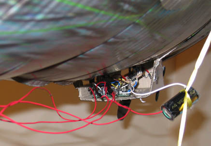 The MCU/PCB and isolator circuits housed in the gondola
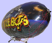
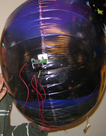 Front view of the blimp