
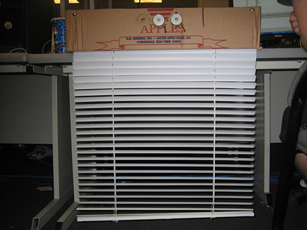
Figure 1. The window shade system.
Introduction
The self adjusting window shade will automatically raise, lower, open, and close your blinds by itself. A computer terminal acts as a remote to broadcast instructions to the window shade via RF. These manual adjustments are stored into the microcontrollers system along with the rooms current ambient light and temperature settings. When these lighting and temperature conditions are found in the room, the window shade will automatically readjust itself to that previous level.
Back to topHigh Level Design
Rationale
We got based our design off Lutrons Sivoia shading solutions (youtube video found here). The Lutron system features that we were especially interested in were the remote functionality, and the automatic capabilities of the shade. We noticed that it might also be favorable to create a memory system within the window shade that would allow it to remember the users previous settings and automatically adjust based off the current conditions in the environment. In addition we created a radio frequency unit that connected the window shade to a computer system that would be able to not only manually adjust the window shade settings, but potentially control entire systems within the home.
Background Math
Memory Table Organization
The nodes in the memory table are set by using Chebyshev nodes. Chebyshev nodes take an even distance along the unit circle, making points at the ends closer to each other while points in the middle further away. We used this design because we felt that there is more tolerance in shade conditions in the middle ranges than at the extreme ranges.
Chebyshev nodes are defined by the following formula: x_i = (a+b)/2 + (b-a)/2*cos((2*i+1)/(2*n+2)*pi) for n+1 nodes where (a,b) is the range, and 0 = i = n. To determine the light nodes we set n = 7 (8 nodes) to get 9 regions between 0 and 255. To get the temperature nodes we set n = 3 (4 nodes) to get 5 regions between 100 and 180. We chose these boundary points because we do not expect the shade settings to change when the temperature of the house falls below 50°F or rises above 90°F. Even those this might also be the case for the light settings, we decided to leave them because the light setting referenced is based off the difference in light.
The nodes from the Chebyshev formula for light are as follows:
[2.4499 21.876 56.6648 102.6260 152.3740 198.3352 233.5124 252.5501]
The nodes from the Chebyshev formula for temperature are as follows:
[51.7127 63.8896 81.1104 93.2873]
These nodes were rounded to integer values to conserve memory usage and make it easier to compare.
Logical Structure
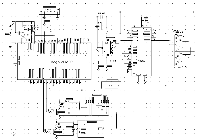
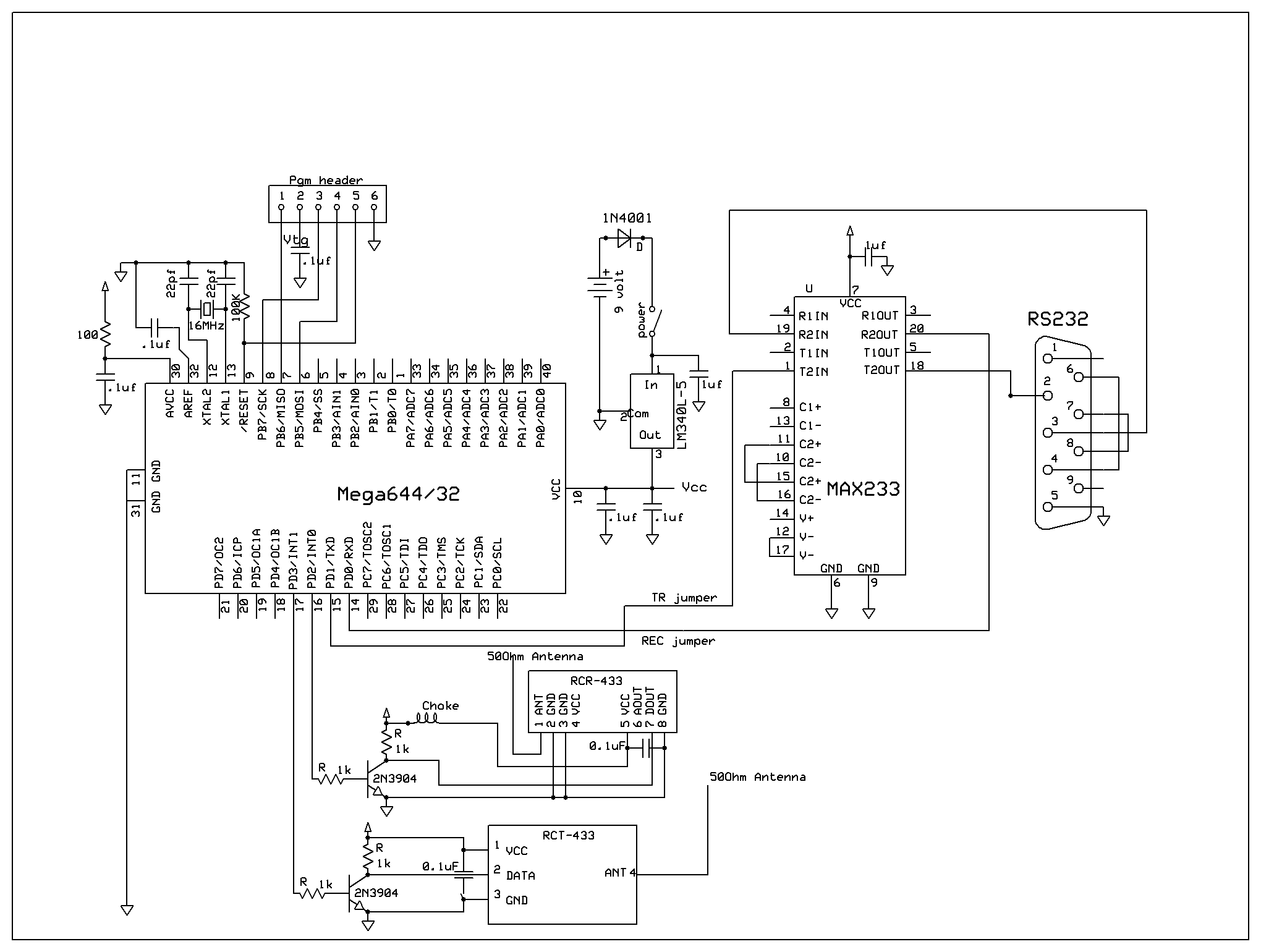
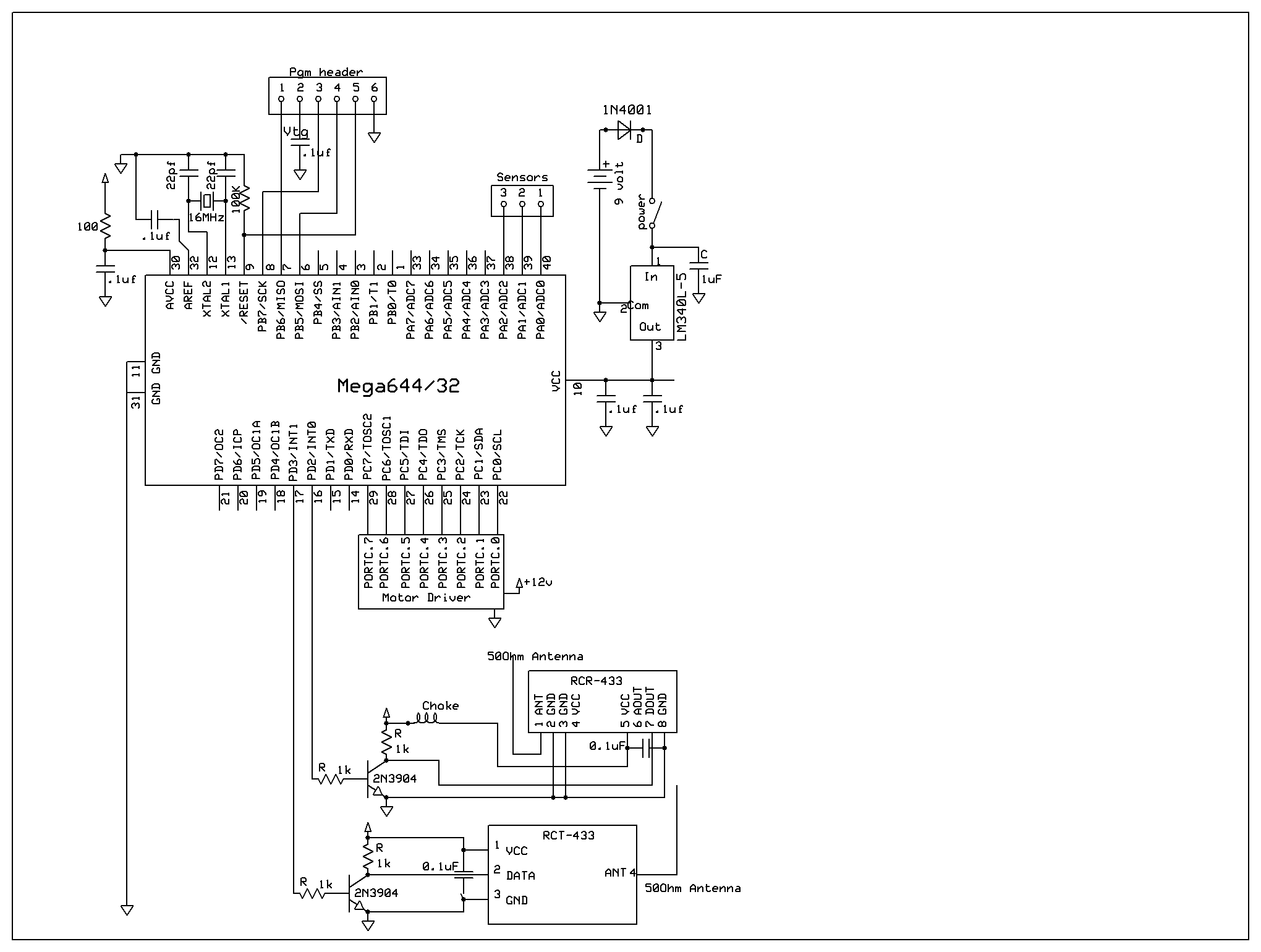
Our design contains two ATMEL Mega644 Microcontrollers: one to control the computer interface and the other to operate the window shade. The first ATmega644 connects to the computer terminal. Hyperterm allows the user to input commands to the MCU to send and/or receive data. They are then transmitted through the RCT433 to the receiver on the other MCU
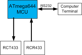
Figure 2. Computer terminal MCU setup
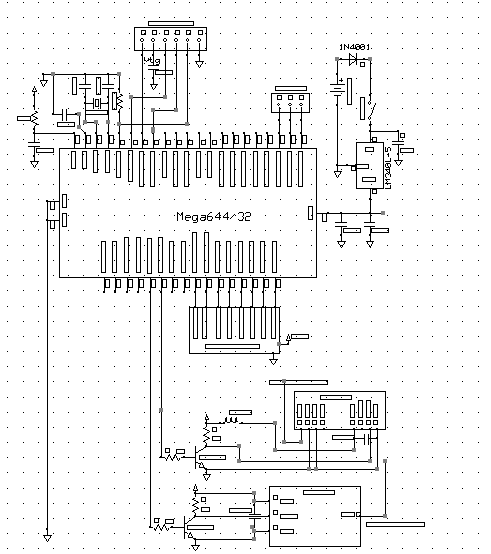
The second MCU contains two modes of operation: automatic and manual. During manual mode the MCU receives the data transmitted from the first MCU and processes instructions, moving the shade to the desired position. When it is not receiving instructions, the MCU switches to automatic mode, where it adjusts the blinds to the users previous settings depending on the lighting and temperature conditions in the room. The MCU then sends a signal out to the motors to rotate them the correct amount to adjust the shade.
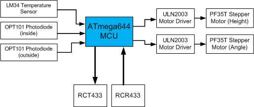
Figure 3. Window Shade MCU setup
The detailed schematics of these designs can be found in the Appendix.
Hardware/software Tradeoffs
The motor can be driven with half-step or full-step configurations. Half-step was preferred because it provided more driving power. Unfortunately, this increased power consumption. Since power consumption isn't a metric for this project, this was an acceptable solution for increasing the strength of the weak stepper motors.
The resolution of the position of the blinds and flaps must be balanced with memory size. The position is stored for a certain configuration in a table. The position is sized to be a byte, allowing 256 possible positions. If the position had been sized as an int, allowing 65536 positions, the memory needed to map configurations to possible positions would grow by about 256 times the length of the table. The length of the table that stores possible configuration options is determined by the degree of tuning required for setting automatic points. For finer responses to conditions, more entries would be required. While the current configuration does not fully utilize data space, it provides adequate response to conditions as well.
When discussing methods to implement a second UART, the solution of a secondary hardware UART on the ATMega644P was overlooked. While a hardware solution is more favorable, due to simplicity of implementation, a software UART allowed finer control over the transmission rate. In order to mitigate risks of malfunction of the RF transmitter/receiver pair due to running the baud rate close to its specification, a lower baud rate may be selected. Due to the nature of the timers, this baud rate does not need to be quantized by the resolution of the hardware USART control registers (i.e. not limited to the micro controllers limited selection of baud rates). Half-duplex communication was also desired due to the shared bus property of the RF channel and the lack of any frequency multiplexing.
Due to the interactions between various interrupts, especially the critical areas of sending/receiving data over the RF link, the timing of the motor update interrupt and the software UART interrupts must be long enough to avoid loss of data. For example, the software UART sampling rate must be long enough for the delay of a motor interrupt to complete processing, hence sampling bits consistently at the correct time. This assertion would limit the baud rate, but since the baud rate is already limited by the RF modules, this factor can be safely ignored.
The controllability of the window shade presented a usability trade off. While the user should be given the freedom to enter any arbitrary adjustment value, overestimating adjustment values would cause the shade to make drastic adjustments and the user to panic. From an interaction perspective, limiting the adjustment range to a constant allowed the user to see enough feedback without taxing the ability to immediately respond to drastic changes.
Existent Patents
The concept of motorized window shades is nothing new with the current energy conservation strategies. Patent 7389806 discusses a motorized window shade and communication system to raise and lower the shade. The idea of the motorized window shade has already been implemented by several companies such as Lutron and Draper. However, none of these companies has implemented a memory system that would allow the window shade to operate independent of human control
Back to topHardware
RF Communications Network
From the beginning, one of the goals of the project was to provide a method for interfacing with multiple remote devices. One of the simplest network topologies for this purpose is a star topology.
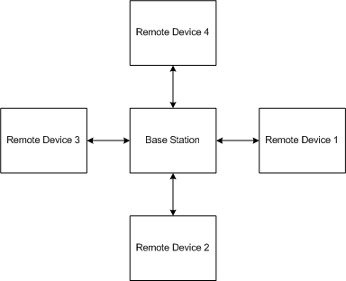
Figure 4. RF Connections to base station
Such a topology is reasonable due to the lack of interaction between remote devices. The base station controls all the remote devices so it is the most authoritative node on the network and is located in the middle of the star. To lighten the load on the base station, and consequently the gateway device (e.g. computer) controlling the base station, the assertions that only one remote device is transmitting while the base station is receiving and all remote devices are receiving while the base station is transmitting must hold true. The RF communications link is essentially a shared bus. Consequently, frequency multiplexing, which would allow multiple remote devices to communicate with the base station, is too complex for this project.
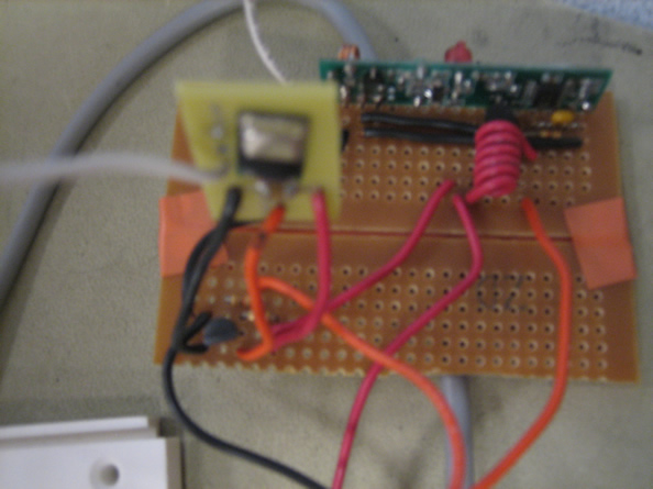
Figure 5. RF Transmitter and Receiver Circuit.
Blind Movement
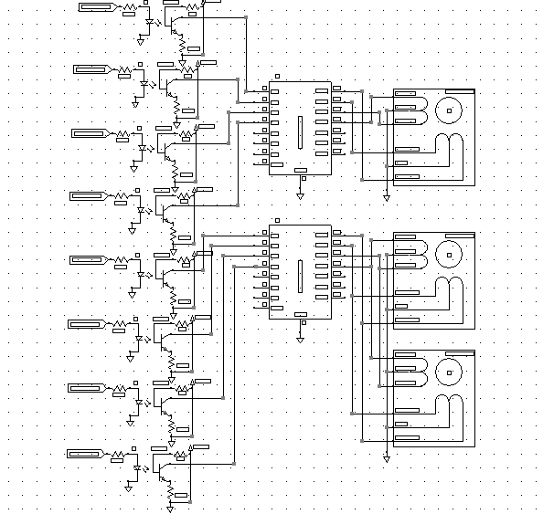
The blinds are moved up and down using 2 PF35T-48L stepper motors. The motors are optoisolated using 4N35 isolaters and powered by a ULN2003A Darlington Array. The stepper motors are used because of their accuracy since the blinds are expected to stop at specific positions depending on the user's previous preferences. They both drive a single gear that increases the torque in the system, allowing shades to be reaised smoothly. Spools are used to roll up the string that holds the window shade. Pulleys are used to redirect the force of the pulling so that the single gear and rod are able to raise and lower the shade. The string goes through the holes of the original window shade frame, so that its outside appearance looks exactly like a normal window shade.
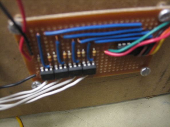
Figure 6. Optoisolator and Darlington Array Circuit
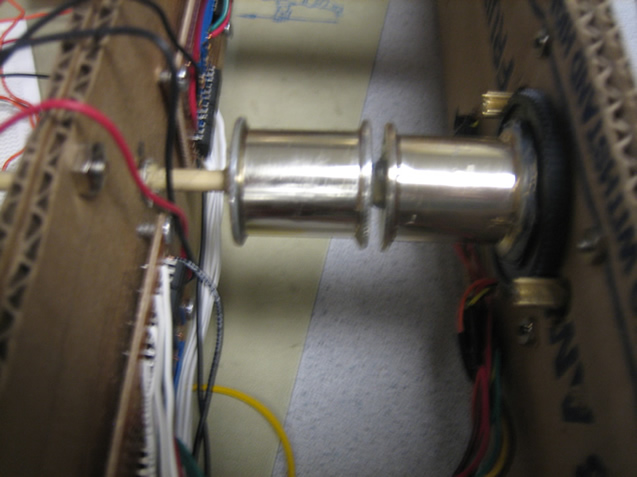
Figure 7. Spools used to raise and lower shade.
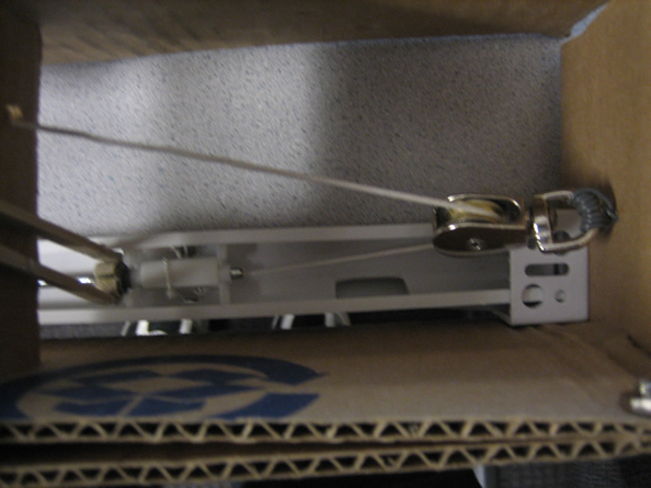
Figure 8. Pulleys were used to adjust the direction of pull force.
Sensor Input
Temperature input is done by the use of the LM34 sensor (same as one used in lab 5). It is amplified by a gain of 2 using the LM358 for greater accuracy before entering the ADC in the MCU. The temperature sensor input goes into port A.0 of the shades MCU. The current room temperature is then calculated from the ADC value and used to determine the settings of the shade.
The light sensors we used are monolithic photodiode and single-supply transimpedance amplifiers OPT101 from TI. The light output increases linearly with light intensity. The photodiode has an internal amplifier with a 1MO resistance, which is used when pins 4 and 5 are connected together. Because of this amplifier, we could directly insert the output of the photodiode into the ADC in the MCU. The light sensors go into ports A.1 (inside sensor) and A.2 (outside sensor). We used a 5V regulated input from the MCU. At bright lights, the sensor read up to 4.27V on the voltmeter while getting a .06V when covered up.
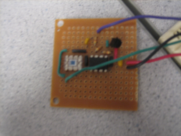
Figure 9. Inside Sensors Circuit.
Hardware Complications
Our first hardware complication came from pulling the shade up. We created our initial design and test code to operate the motors to raise and lower one side of the shade, while one person would manually lift the other. We quickly realized that the motor was not strong enough to lift it's side of the shade. We then purchased pulleys and created a pulley system to assist in lifting the shade. This too failed, as the shade only made it about half way up before the motors no longer had enough torque. Finally we purchased a gear to significantly increase the torque of the system. This provided enough torque to lift the shade. We were hoping to purchase a second gear to implemente a symetric system for the other side of the shade, but we were unable to find another one as the vendor only had one gear with the correct teeth. So we attached the second motor so that and tested it, finding that this provided enough torque to lift both sides of the shade with one axel and gear.
Back to topSoftware
Secondary UART for RF Communications
To facilitate communication using the RCR/T-433, the use of a UART connection seemed especially salient. Unfortunately, on the base station, the hardware UART was already used for communication with the gateway device. Due to the lack of research into alternative microcontrollers, such as the ATMega644P, and budget constraints, an interrupt-driven software UART was implemented. While a software solution is nowhere as efficient as a hardware solution, it is cheap, low-cost, and conceptually simple to understand.
The software implementation was loosely based on AVR304, which describes a half-duplex interrupt-driven UART using a timer and an external interrupt based on the bit-banging method. As noted in the design of the RF network, a half-duplex serial communication method is adequate and ideal for the project, due to the shared nature of the baseband frequency. The only hardware cost of this implementation is the use of two GPIO pins. In terms of software cost, an external interrupt and a timer are used.
The software implementation involves transitioning the software UART through a number of control states.
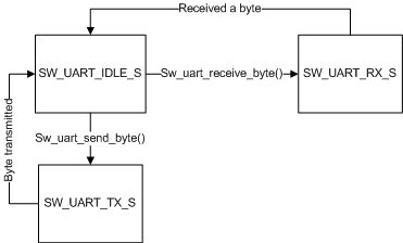
Figure 10. Software UART State Machine
SW_UART_IDLE_S The channel is free or a byte has just been received or transmitted.
SW_UART_RX_S The channel is occupied waiting for a byte to be received.
SW_UART_TX_S The channel is occupied transmitting a byte.
sw_uart_send_byte activates a timer interrupt which sends a start bit (transmission of a falling edge), followed by a byte of data, and a stop bit (transmission of a rising edge) at the baud rate. Since the subroutine only enables the interrupt, it is non-blocking and other operations may be performed while a byte is being transmitted. After a full byte is transmitted, the channel is free.
sw_uart_receive_byte activates the external interrupt to capture a state bit (falling edge). After the interrupt is triggered, a timer begins to sample the incoming data stream at the baud rate of the connection. Again, this subroutine only enables the relevant interrupts. It is non-blocking and other operations may be performed while a byte is not received. After a full byte is received, the channel is freed. After a byte is captured, the received data is stored to a variable.
RF Data Encapsulation
The transmitted frame is composed of 15 bytes transmitted continuously.
| [0] | [1...4] | [5] | [6...13] | [14] |
|---|---|---|---|---|
| 0x00 | Sync Sequence | Start | Encoded Payload | Stop |
The first byte (index 0) is necessary to adjust the receiver gain and clear any noise-triggered interrupt byte captures by the receivers. The sync sequence is used to allow the receiver to acknowledge the upcoming frame as an actual frame and not noise. The start byte is used to signal the receiver to begin storing the encoded payload during subsequent byte captures. Finally, while the stop byte is not used in the project, it can serve both as a terminator marker or error checking.
The payload must be encoded to provide DC normalization. Following work done by Meghan Desai, the following scheme is used to encode the payload and payload bytes are sending with least significant nibble first.
| Nibble | Encoded Byte | Nibble | Encoded Byte | Nibble | Encoded Byte | Nibble | Encoded Byte |
|---|---|---|---|---|---|---|---|
| 0x0 | 0b10001011 | 0x4 | 0b10010110 | 0x8 | 0b10100011 | 0xC | 0b10101100 |
| 0x1 | 0b10001101 | 0x5 | 0b10011001 | 0x9 | 0b10100101 | 0xD | 0b10110001 |
| 0x2 | 0b10010011 | 0x6 | 0b10011010 | 0xA | 0b10100110 | 0xE | 0b10110010 |
| 0x3 | 0b10010101 | 0x7 | 0b10011100 | 0xB | 0b10101001 | 0xF | 0b10110100 |
The payload is formatted to support 254 devices with 254 possible sensory values/commands per device. The format of the decoded payload from the transmitter follows this format.
| [0] | [1] | [2] | [3] |
|---|---|---|---|
| Address of Device | Command | Argument 1 | Argument 2 |
0x00 is reserved in the address space for the base station and in the sensor ID space for acknowledgment. In the specific case of the self-adjusting window blind, the following commands are supported and transmitted from the base station.
| Command Code | Argument 1 | Argument 2 | Description |
|---|---|---|---|
| 'O' | Relative Amount | Don't Care | Opens the flap a relative amount. |
| 'C' | Relative amount | Don't Care | Closes the flap a relative amount |
| 'U' | Relative amount | Don't Care | Lifts up the blind a relative amount |
| 'D' | Relative amount | Don't Care | Lowers the blind a relative amount |
| 'A' | Absolute blind position | Absolute flap position | Positions the blind to the absolute blind and flap positions. |
| 'R' | Sensor ID | Don't Care | Polls the sensor with sensor ID for a value |
In contrast, the remote device only transmits the following payload format.
| [0] | [1] | [2] | [3] |
|---|---|---|---|
| 0x00 | Remote Device Address | Sensor ID | Value |
In the case of non-value returning operations, such as blinds adjustments, the value 0x00 is reserved for sensor ID and 'A' is used as the value for acknowledging receipt of the command. With a value returning operation such as 'R', the sensor ID corresponds to the requested information and the value is the returned value. Fault-detection and error-handling, such as resending commands in case of a time out is handled by the gateway device driver. The following encoding for information from base station to gateway device facilitate this exchange.
| Code | Meaning |
|---|---|
| 'W' | Sending command to remote device. |
| 'D' | Done processing a command |
| 'F' | Error processing command. Probably not recognized |
| TO | Command to the remote device timed out. ACK was not received. |
| Rxyz | x is the remote device address, y is the information ID, and z is the return value. (0x00 is reserved for y for confirmation of a command with no return value. z will be 'A' for acknowledgement. |
RF Communication Link Control
The RF control component facilitates sending and receiving entire packets of data. RF controls must be non-blocking with serial communications, but due to the heavy use of interrupts through the rest of the project, a non-interrupt driven control from the main while loop will be used. With this implementation, the assertion that the control procedure will be called fast enough to not miss any packets must be imposed.
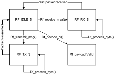
Figure 11. RF Connections to base station
RF_IDLE_S The RF channel is cleared or a valid frame has just been transmitted or received.
RF_TX_S The RF channel is occupied with blasting a frame through the software UART.
RF_RX_S The RF channel is waiting for a valid frame to be received.
Rf_payload Valid The received frame has been decoded and the rf_payload variable contains the decoded data.
rf_transmit_msg() encodes a payload and loads it into a transmission buffer. No interrupts are enabled and the frame is not actually processed.
rf_receive_msg() enables software UART byte capture and resets conditions for the received frame buffer.
rf_process_byte() either reads a byte from the software UART when it is ready or enables a transmission of a byte through the software UART. This calls either sw_uart_receive_byte() or sw_uart_send_byte(). The race condition between processing a byte from a received string and starting the software UART in time to capture the next byte is acknowledged. However, the stop bit of a received stop byte and the length of the synchronization sequence should provide enough time for process_byte() to be called again before any of the encoded payload data is lost.
A timeout is imposed to handle the condition where a remote device might be off or out of range. The base station waits for an acknowledgment message after transmitting a command. If no acknowledgment is received within the timeout duration, an error message is sent to the gateway.
Back to topMotor Control
Stepper motors operate by energizing coils sequentially in order to turn the armature and produce rotation. In a single step configuration, only one coil is energized at a time. However, in the project, the stepper motor is configured to turn at half-step increments. Driving a motor at half step provides additional driving power while consuming more electrical power. Furthermore, it also provides double the precision of the full step configuration. The sequence used to drive the rotation of a stepper motor is given in the following figure.
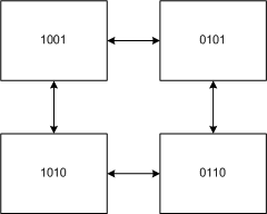
Figure 12. Stepper Motor State Machine
To drive the motor at a particular speed, a timer is used. The turning rate of the motor is determined by the half the step size (using the half-step configuration) times the frequency of the timer. Increasing the frequency and proceeding through the motor control sequence faster will result in faster revolutions. Driving the motor at a constant speed is important smooth blind movement. Thus, motor control is relegated to a timer that triggers an interrupt to change the motor output at about 2 revolutions per sec. The motor interrupt is determined in part by the current motor output. To ensure smooth movement is attained, only one transition to adjacent states can be made during a single cycle of the timer.
The timer interrupt handles converting step size to position through a scaling factor. A position describes either vertical position of the blind or the angle of the flap. The resolution of position is height of the shade divided by 256 (represented in one byte). The scaling factor is determined by the number of steps needed to move one position. By careful bookkeeping, positions in absolute space can be maintained accurately. Adjustment to the shade is limited to these positions while trading off memory size and fine-tuned control. After the number of steps per position is completed, the position bookkeeping is adjusted and the adjustment variables are decremented.
The timer continuously adjusts the motor to neighboring states based on the four adjustment variables:
- adjup_pos Adjusts the shade upwards
- adjdown_pos Adjusts the shade downwards
- adjopen_pos Adjusts the angle to open
- adjclose_pos Adjusts the angle to close
By setting the adjustment variables to a non-zero positive number, the timer will automatically control physical motor movement to complete the adjustment without blocking any control from the communication components. Initially, the use of two variables allowed us to queue movements up and down so it would complete all upward movements before downward movements (or all open before close). However, after additional consideration, the ideal seemed novel and not extremely useful. Therefore, when setting the adjustment variables, the complementary adjustment (e.g. adjdown_pos when setting adjup_pos) should be zeroed. The ability to store the configuration into memory at a certain point is more beneficial than storing the position at the end of movement.
Back to topResults
Speed of execution
The motors running the shade are non-block and can be overwritten by a manual command at any time. When a manual command is entered, the previous command is erased and the new command is ssued. This works well for quick and immediate adjustments, when the user might want to stop having the shade adjust automatically and take that point as a storage value. This also removed a previous flicker that would resultfrom the shade having commands to move up and down at the same time, causing the shade to shade and often lose steps in rotation, decreasing the accuracy of the shade. Now that there is only one command, the shade does not have conflicting adjustments.
Both adjustments of the shade flicker then the sensor values produce a value that is very close to a node. This is because the data at the nodes are not smoothly connected, but rather the settings are split into segments. So if the sensor value is hovering around a node, it will attempt adjust back and forth betwen the two range settings as the sensors go above and below. The motors keep attempting to readjust and never shut off. To correct this, we would need to implement a new methodology for the memory system, perhaps using a bilinear interpolation function and to create a continuous curve. The reason that we did not implement this memory model was because of the computation that would be needed to achieve the smooth function. Each calculation of one variable (height or angle) would require eight multiplies. This means that we would need 16 multiplies every loop through the code.
Accuracy
The stepper motors provide the system with very good accuracy, allowing it to get exact points in the window shade levels. We split our shade into 255 steps, or positions the shade can stop at. Each of these steps takes a certain number of rotations, which is given in the steps_per_position. The only flaw in the accuracy of the shade occurs when the motors do not have enough torque to rotate the shade or open the blinds and the motors either slides or clicks. This happens much more ofthen near the top of the shade, when the motors must lift the entire weight of the shade. When this occurs the step is dropped and the shade is now at an incorrect position. To fix this, we have a calibrate function, which brings the shade all the way to the top (regargless of clicks or skips) and then resets the position to zero.
Safety
The stepper motors normally heat up a significant amount because there is a good amount of power required to run the motor. To account for this, we shut the motors down when they are not moving the shade. We do this by sending the motors a byte of low bits, meaning no voltage goes to any of the motor inputs. Not only does this prevent the motors from overheating, it also reduces power consumption. Other than that, our window shade is about as safe as another other window shade commonly found in a home.
Interference
The transmitters send out RF signals at a frequency of 433 MHz. This would intefere with anyone else that transmits or receives at this frequency. Our project sorts through interference by having an address associated with each receiver. In the case that there is more than one remote device, the address byte is used to determine what data is useful to that specific device. Any signal not containing the device address is ignored.
Useability
Our project is highly practical in the real world setting. Although it might not be the best case to have memory in every single window shade (very dependent on the location and the memory design), it is very useful for most situations. The entire device fits into a frame that is small and can be easily covered by a curtain, as per normal window shades. This project can be implented on multiple window shades to control all of them with a single control source.
The other useability feature is our computer interface. As explained, it is able to handle transmission to not just the window shade, but any number of remote devices (as long as there are enough addresses). This means that the single base station can control up to 256 remote devices. The base station can be expanded to operate lighting, fans, and many other household components.
Back to topConclusions
Expectations
We were suprised how much the budget influenced our project. Originally, we had planned to implement the window shade using solar power and batteries to make it more eco-friendly. However after some research we realized that it was too expensive to afford a battery and panels that would be able to consistently run the motors and charge the battery at the same time. We therefore resorted to the typical wall socket power.
We faced some trouble lifting and adjusting the shades at its extreme points (raising the shade all the way up or rotating it completely in one direction). However, we expected some of this difficulty as we attempted to use the less powerful stepper motors to create the memory system. In the end, it would have been better for us to use stronger motors and design our frame out of a sturdier material such as wood. However, due to time and resource constraints, we were unable to complete these tasks.
Intellectual Property Considerations
The only portion of the product not created from scratch is the window shade itself. Other than the window shade, we made everything from raw materials.
A portion of our code for the software UART came from the base code given by Atmel. Other than that, all our code was self-written and designed within our group.
Ethical Considerations
Throughout this project we have done our best to uphold the IEEE Code of Ethics in creating a product that is safe and useful in advancing technology. We placed high value in the public welfare and safety in designing our project. We did not encounter any conflicts during the project. We designed this product to the best of our ability in its electrical circuitry and wiring. There have been no cases of bribery, which we would not accept if there was. We took technologies that we were familiar with and attempted to combine them in a useful way. We saught the aid of not only Professor Land and the TAs but also a few friends that had previously taken ECE 476. We often talked to other groups or different races, genders, religions, and other various diversities regarding their projects and received feedback on ours as well.
Legal Considerations
We are transmitting at 433MHz, which is within the free transmission range. Other than the tranmission, our window shade is acting as a fully operational normal manual window shade. There are no other legal issues to consider.
Back to topAppendix
Source Code
Program Files
main.c
rfcomm.c
serial.c
softuart.c
stepper.c
uart.c
Header Files
main.h
ops.h
portdeclarations.h
rfcomm.h
serial.h
softuart.h
stepper.h
uart.h
Schematics
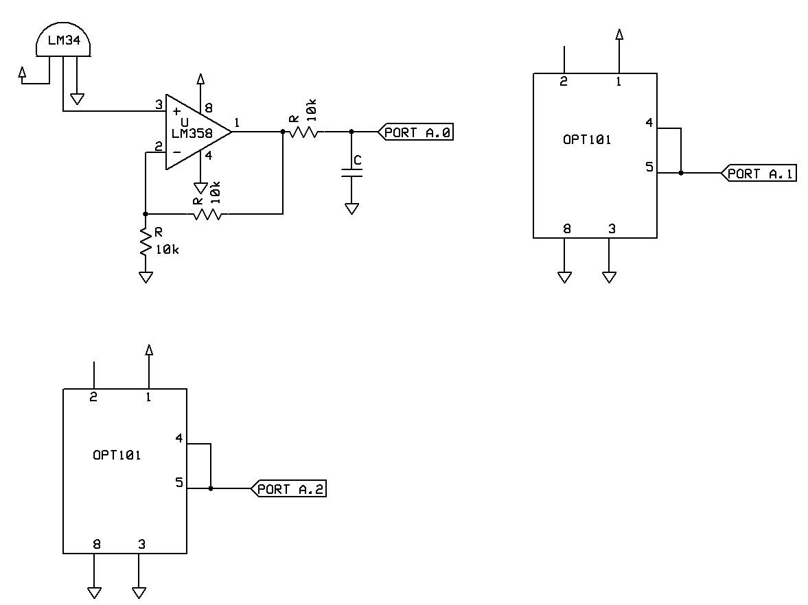
Figure 16. Sensor Schematic sch file
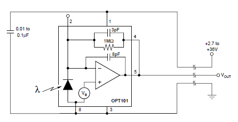
Figure 17. OPT101 Photodiode Schematic
Costs
| SECTION | ITEM | QUANTITY | PRICE | TOTAL |
|---|---|---|---|---|
| Total | 72.45 | |||
| Motors | PF35T-48L Stepper Motors | 3 | 1.00 | 3.00 |
| Motors | ULN2003 Darlington Array | 2 | 0.64 | 1.28 |
| Motors | 4N35 Optoisolators | 8 | 0.25 | 2.00 |
| Motors/RF/Sensors | small PC board | 5 | 1.00 | 5.00 |
| Motors | Pulleys | 2 | 2.75 | 5.50 |
| Motors | Spools | 2 | Scrapped | -- |
| Motors | Rubber Bands | 4 | Previously Owned | -- |
| Motors | Chopsticks | 1 | Scrapped | -- |
| Motors | Gear | 1 | 4.00 | 4.00 |
| MCU | ATmega644 | 2 | sampled | -- |
| MCU | DIP sockets | 3 | 0.50 | 1.50 |
| MCU | MCU solder boards | 2 | 1.00 | 2.00 |
| MCU | MAX233 | 1 | sampled | -- |
| MCU | RS232 | 1 | 1.00 | 1.00 |
| RF | RCR-433 RF receiver | 2 | 4.00 | 8.00 |
| RF | RCT-433 RF transmitter | 2 | 4.00 | 8.00 |
| MCU/Motors | Power Supply | 3 | 5.00 | 15.00 |
| Sensors | OPT101 Photodiode | 2 | 5.50 | 11.00 |
| Sensors | LM34 Temperature Sensor | 1 | 2.51 | 2.51 |
| Shade | Window Shade | 1 | 2.66 | 2.66 |
| Shade | Cardboard | a lot | scrapped | -- |
Task Distribution
- RF sensors - Henry
- Motor Hardware - Alex
- Frame Design - Alex
- Software - Henry
- Memory Table Design - Alex
- Testing - Both
- Soldering - Both
- Report - Both
- Webpage - Alex
References
Data Sheets
ATmega644
OPT101 Photodiode
LM34 Temperature Sensor
RCR-433 RF Receiver
RCT-433 RF Transmitter
PF35T-48L Stepper Motor
Referenced Code/Designs
Shawn Liang and Mark Udoff Stepper Motor Schematic
Wireless Protocol by Meghan Desai Link
AVR-304 Application Note
ECE476 Lab 5 Sensor Schematics
ECE476 Lab 0 UART Code