Hosted on the Cornell ECE 4760 Final Projects Webpage
Introduction
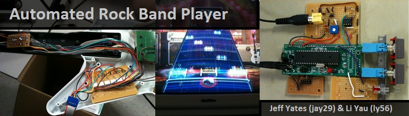
For our final design project, we built an automated Rock Band player that can beat any Rock Band song by decoding the Xbox 360 video output and sending the appropriate button push and strum signals to a modified Xbox controller.
This project was particularly appealing to us because we are both Rock Band fanatics. We had both seen videos of people using bots to beat Rock Band and Guitar Hero songs by using photosensors or by pre-programming the correct button sequence. We had never heard of anyone using the raw video output to decode and beat a Rock Band song and thought it would be a fun and challenging project. The fact that this project combines so many different ECE and CS concepts helped us in our decision as well.
[top]
High Level Design
Rationale and Sources of Project Idea:
The idea for this project came to us early in the course due to our experience playing rhythm
games such as Guitar Hero and Rock Band. We had both heard of devices that use photo sensors
attached directly to the screen to detect notes, but none that actually used the direct video output
of the game console. After lab 3, in which we needed to create a video game and output it to a TV in
pseudo-NTSC format, we learned enough about standard NTSC signals to deem our project feasible. We
believed that this project would give us sufficient hardware complexity, in interfacing the
microcontroller with the Xbox, and software complexity, in analyzing the video signal to determine
notes to be played.
We originally wanted to use a video decoder chip to convert the analog composite video signal into a digital YCbCr signal in order to analyze the precise color and brightness of each pixel. However, we soon learned that YCbCr encodes each pixel in approximately 2 bytes of data. Because the TVP5150AM1 video decoder chip that we had obtained outputted digital video data at a rate of 27.0MHz and our microcontroller only had a clock speed of 16MHz, we realized that there was no way we could consistently sample two consecutive bytes of the video output.
We then stumbled upon www.autoguitarhero.com where someone actually implemented something remarkably similar to what we were doing, except on Guitar Hero for the Wii. Instead of analyzing video data, he simply looked at the amplitude of the video signal at a certain point of a video line and used an analog comparator to see if it passed a certain threshold, thus signifying a note to be played. Running out of time, we decided to scrap our initial plan of analyzing video data and use his approach. In the end, we were able to use the analog comparator on the Mega644 microcontroller to compare the video signal and a reference voltage. We found this to work reasonable well and stuck with it.
Background Math:
Standard NTSC outputs video with a frame rate of about 60Hz with each frame containing 525 lines.
We needed to determine whether our microcontroller was fast enough to analyze specific points in
specific video lines. We made a quick calculation to determine the speed of our microcontroller
relative to the speed of the video:
Line speed: 1/60*1/525≈31.7μs
Microcontroller speed: 1/16000000=62.5ns
We can see that the microcontroller can run approximately 3 orders of magnitude faster than the line speed. Thus we determined it feasible to use it to analyze a video line signal.
Logical Structure:
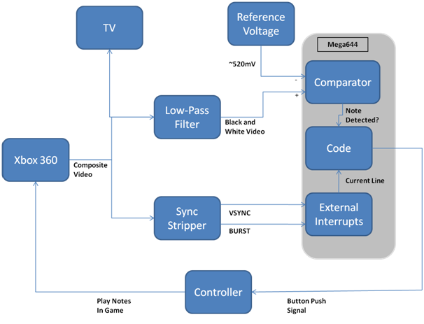
The primary input for our project is the composite video signal from the Xbox360. We split this signal
sending it to the TV, analog comparator, and sync stripper. The signal to the TV simply displays the
game on the screen. The sync stripper outputs the VSYNC and BURST signals from the composite video
signal signifying a new line and new frame respectively. We feed these into the external interrupt
pins of the Mega644 and use the external interrupt ISRs to count the lines and clear the counter at
the beginning of every frame. Before the video signal is sent to the analog comparator, we send it
through a low-pass filter to filter out the color sub-carrier frequency, leaving only the brightness.
Because notes are brighter than the background, we know that if a certain point on the screen has a
note on it, it will be brighter. Thus we use the analog comparator along with a reference threshold
voltage to signal if a note is on the screen. Finally we use our code to only check the comparator at
specific sections of specific lines to detect the presence of a note. If a note is detected, we send a
signal to our modified Xbox360 controller to play the note in the game.
Hardware/Software Tradeoffs:
Early on we determined that in order to maintain strict timing requirements needed for the NTSC
video signal, we needed to use some sort of external chip to decode the composite video signal. This
would be more accurate than the microcontroller and free up computing power for video analysis. We
originally used a TVP5150AM1 video decoder chip but discovered that it outputted digital video data
faster than we could analyze it. Because our project deadline was fast approaching and our budget
limitations we decided to simply look at the amplitude of the video signal to determine if a note
needed to be played. We used a basic low-pass filter to filter out most of the chrominance leaving
only the luminescence and fed the resulting signal into the analog comparator of the Mega644. With a
propagation delay of 500-750ns, we determined this to be sufficiently fast. In the end, our device was
reasonably accurate, but noise from the signals caused variation in the video input preventing us from
reaching 100% accuracy.
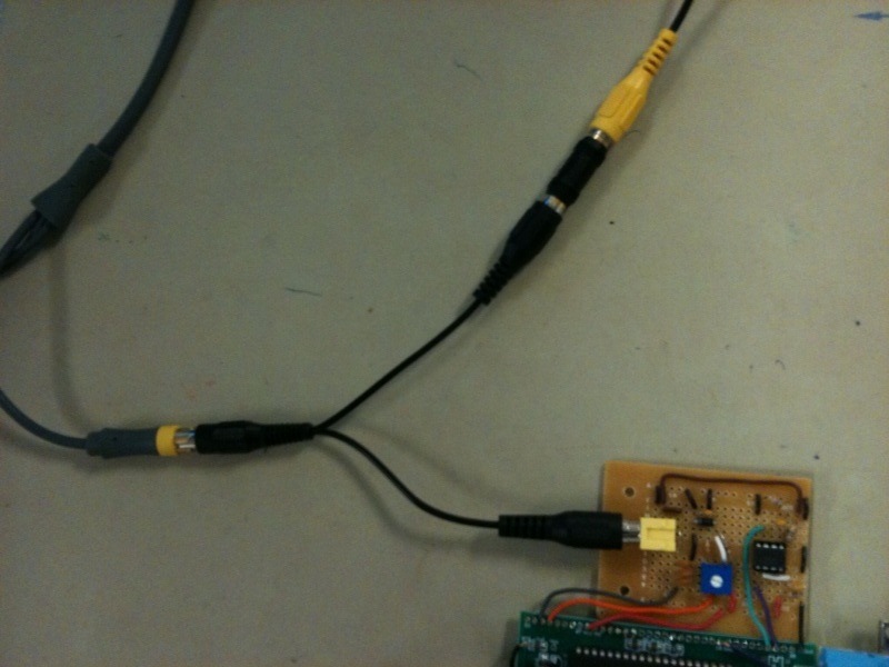
To split the composite video signal so that it could be inputted to both our device and the TV, we used a standard cheap 2-way RCA splitter due to budget considerations. Although this worked reasonably well for our purposes, the lack of amplification dropped the voltage on the video signal and introduced slight degradation in video quality.
Relationship of design to standards:
NTSC is the standard analog television system used in the United States in is outputted by the
Xbox360s sold in North America. It consists of 29.97 interlaced video frames per second with 525
scan lines per frame. Interlaced frames mean that every frame is divided in half. In the first half,
all the even lines are drawn and in the second half, all the odd lines are drawn. This effectively
increases the refresh rate to 59.95Hz producing a flicker free image to the human eye. Only 486 of
the 525 lines actually contain visible data while the remainders of the lines are used to synchronize
the TV and retrace the display to the top of the screen.
The basic NTSC signal uses voltage bursts to signify the beginning of a line, HSYNC, and the beginning of a frame, VSYNC. Every new line is signified by a single burst while new frames are signified by a series of successive bursts. As a line is being drawn across the TV screen, the voltage of the signal determines the brightness of the specific point on the screen. Thus, based solely on timing, it is possible to consistently determine whether or not a point on the screen is bright or not. Color is added to the signal by adding a 3.579545MHz subcarrier frequency to the signal.
Void Warranty and Electrical Shock:
By opening and modifying the Xbox 360 controller, we void the warranty. Xbox also warns of potentially
dangerous electrical shock from opening the Xbox or its accessories. However, the power supplying the
guitar was low voltage and current, leaving little chance of harmful shock. In addition, the power to
our device comes from a 12V, 500mA transformer, which also leaves little chance of shock.
[top]
Hardware Design
All hardware schematics are located in Appendix C: Schematics
Xbox and Video Splitting:
Rock Band is played on the Xbox 360 console gaming system made by Microsoft. We chose this system
because happened to have an Xbox 360 already, but the Sony PlayStation and Nintendo Wii would have
also worked for this project. The Xbox 360 generates and outputs video in NTSC 4.43 format over
either composite or component output ports. For this project we are reading data off of the composite
output port.
We needed the composite signal to go to both our device and to a color TV for display. Initially we were worried that using a simple RCA Y-splitter would cause an impedance mismatch resulting in unwanted reflections along the cable and a distorted signal. We looked into the option of matching the impedance to the 75Ω of the cable before a stage of amplifiers that would drive the signal to the TV and our device. Ultimately we tested the simple RCA Y-splitter and found that the signal came through very clear without noticeable distortions. We used an RCA extension cable from the splitter to the TV, and an RCA plug that was soldered directly into our board for the device video input.
Video Sync Stripper:
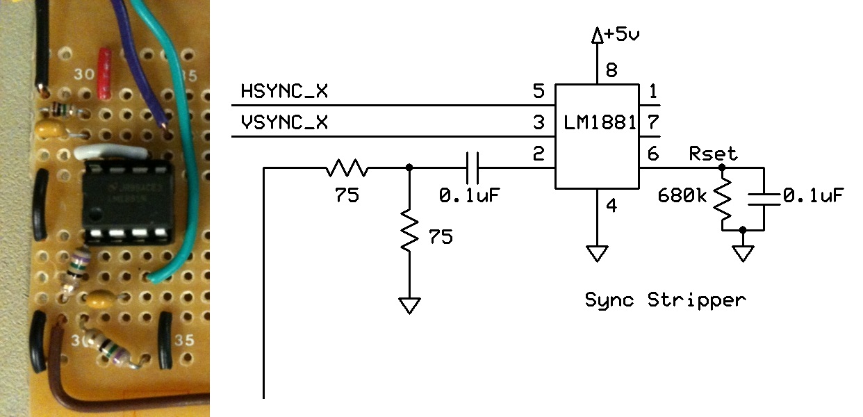
To process the NTSC video signal from the Xbox, first we need to strip the HSYNC and VSYNC pulses
out of the signal. The HSYNC signal tells us when a new line is being drawn, and allows us to count
down to the correct line for button detection. The VSYNC signal tells us when a new frame is started,
allowing us to restart our line counting when the frame resets.
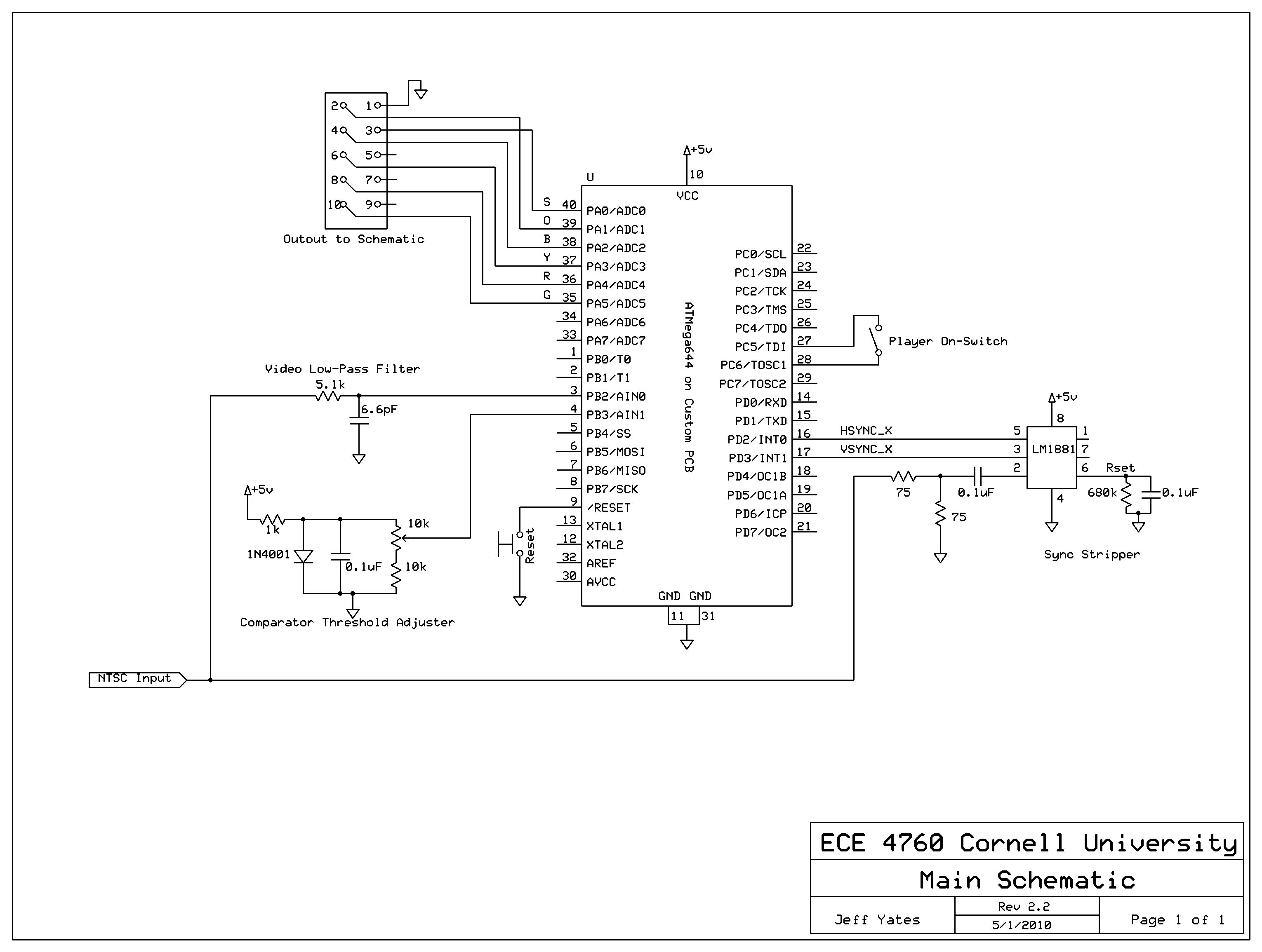
We decided to use the LM1881 Video Sync Stripper made by National Semiconductor. It comes in an 8 pin DIP and supports sync separation for NTSC, PAL, and SECAM video signals. The chip is able to run on the same 5V power supply as the MCU without any additional regulation. It outputs a Vertical Sync Output on pin 2 and a Burst/Back Porch Output signal on pin 5 that act similarly. They are both full swing 5V active low signals that go low whenever a VSYNC or HSYNC is active, respectively. The chip also outputs Odd/Even frame information that is not used in the project.
The HSYNC signal is outputted from the chip to one of the external interrupt pins on the MCU (PORTD.2 / INT0). The VSYNC signal is outputted from the chip to the other external interrupt pin (PORTD.3 / INT1). These interrupts will be used to count lines and frames in our software. The input from the chip comes from one output of the RCA splitter and is passed through a small 75Ω resistor and 0.1µF capacitor for coupling. On pin 6 of the chip there is a 1MΩ resistor and 0.1µF capacitor in parallel to ground to set internal current levels and decouple.
Below is a screenshot from the oscilloscope showing the composite input to the video sync stripper on the top and the resulting active low HSYNC output signal on the bottom.
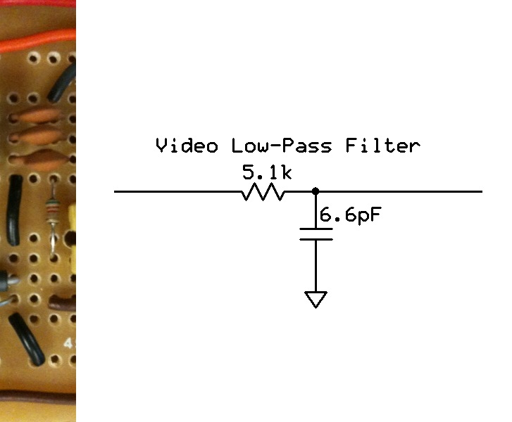
Video Low-Pass Filter:
Standard NTSC video is a color signal that carries both luminance (brightness) and chrominance
(color) data over the same signal line. The chrominance data is encoded using two 3.579545 MHz
signals. For this application we only need the brightness data to compare so we needed to strip the
chrominance off of the input NTSC signal. We accomplished this by designing a low-pass filter with a
cut-off bandwidth of 2.4 MHz. After some testing, we found that using a higher cut-off of 4.7 MHz
gave us the best results. At this value, a lot of higher frequency noise is taken out of the signal,
while some high spikes still remain to trigger our comparators.
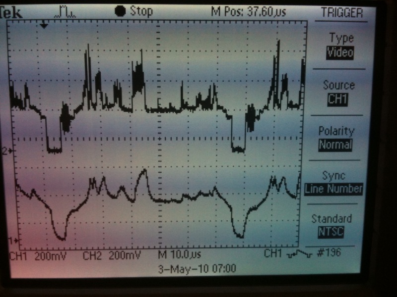
Below is a screenshot from the oscilloscope with the original composite video signal and the output of the low-pass filter. The signal on the bottom is the low-passed output and clearly has fewer higher frequency noise spikes.
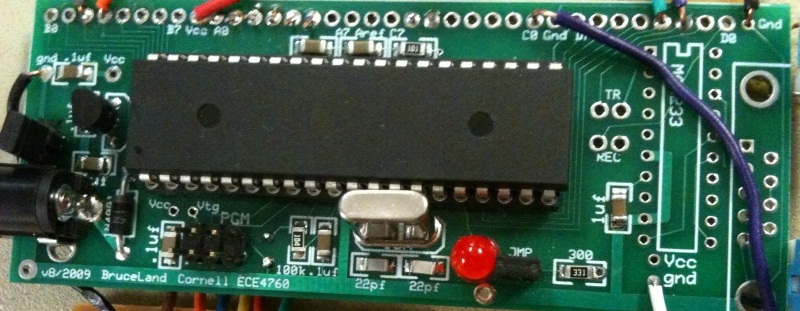
MCU and Prototype Board:
Our implementation uses one ATmega644 microcontroller clocked at 16 MHz. We need several of the
features on this chip including the two external interrupt pins, a fast internal comparator, 4 8-bit
I/O ports, and a fast enough processor to provide the necessary resolution to sample the lines of the
NTSC video signal.
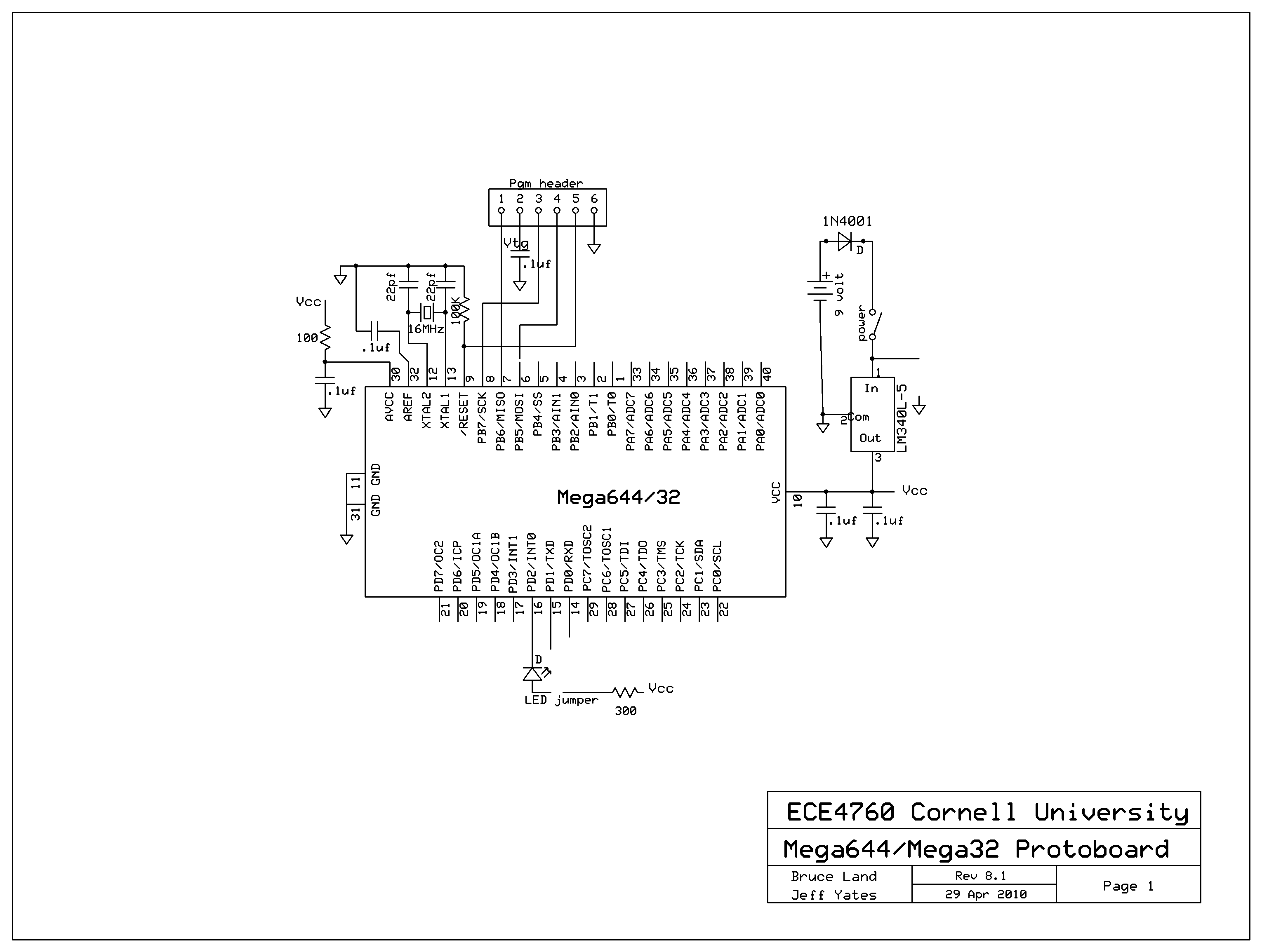
During prototyping, we used the STK500 development board to interface with the Mega644. We were able to take advantage of the serial port and 8 LEDs for debugging, and the many pin header plugs for fast connectivity. However, when our design was finalized we chose to bring the MCU off the large STK500 and onto a smaller printed circuit board (PCB). We used Bruce Land’s 2009 ECE 4760 custom PCB. On this board there is a power supply plug, 5V regulator, 16 MHz crystal, diode, program header, LED, and several resistors, capacitors, and jumpers. We chose not to install the MAX233 chip and serial port, as our project does not use any UART or serial communication. We were able to solder all inputs and outputs directly to the holes in the PC board. More information on Bruce Land’s custom PCB can be found on the ECE 476 Website.
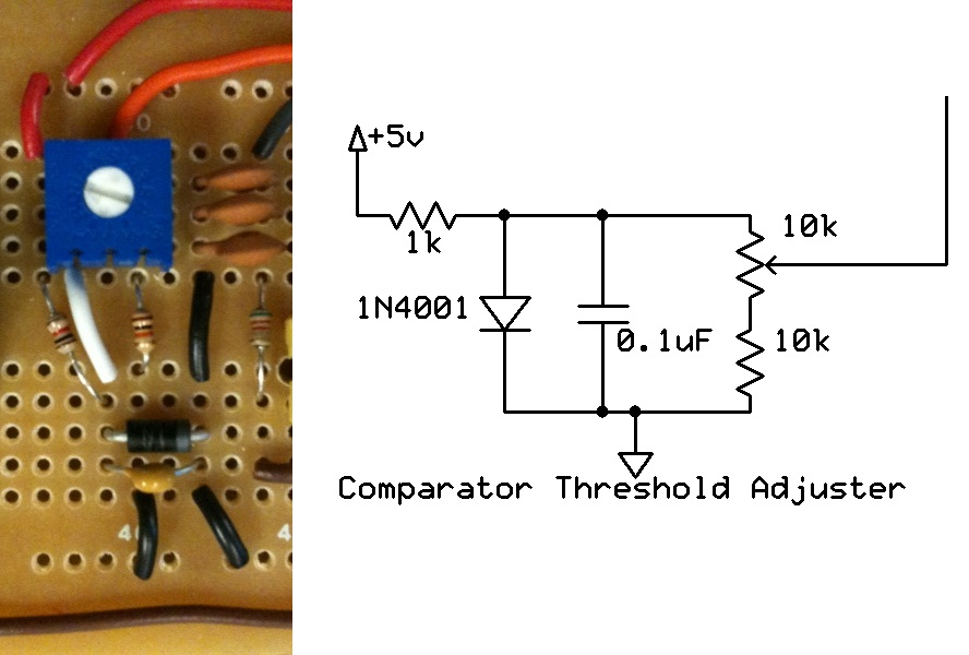
Comparator and Threshold Adjustment:
To detect when a button press is needed, we check for when the button passes over a few lines in
the NTSC signal. There is a large difference in brightness between the dark fret board background and
the bright buttons. This brightness shows up in the NTSC signal as a higher voltage signal. We are
able to distinguish between the different buttons by using software delays to check the brightness at
specific times that correspond to the button “lanes” on the fret board. To check if the brightness is
high enough to be a button, we input the low-passed NTSC into the (+) terminal of the on-board
comparator (PINB.2). We also input a threshold voltage to the (-) terminal of the comparator (PINB.3),
which sets minimum voltage at which the output goes high. When the brightness of the video signal
rises above this threshold the comparator saves a high value into the ACO register, signifying a
button press. The ACO is read at specific times by software, which is determined by the delays
corresponding to the different button lanes.
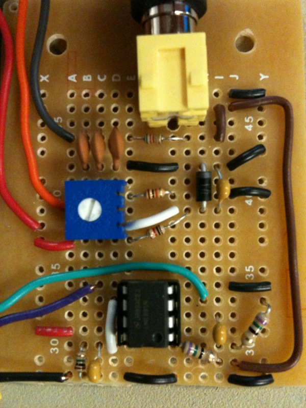
The threshold voltage is an adjustable voltage that we found to yield best results when set at around 520 mV. We designed an adjustable voltage divider using 1kΩ and 10kΩ resistors to set the minimum and maximum possible voltages and then a 10kΩ to adjust between the two voltages. We also put in a capacitor and diode to take out as much noise as possible from the reference signal. Using this circuit we are able to adjust the threshold voltage from 644mV to 56mV by using a screwdriver.
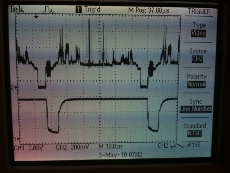
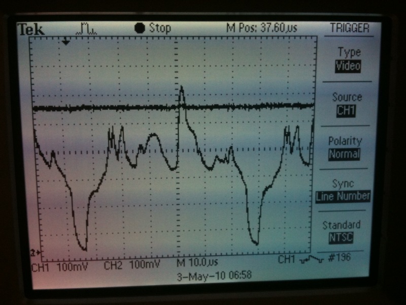
Below is a screenshot from the oscilloscope showing the threshold voltage at about 520mV and the low-pass filtered video signal being inputted to the comparator. In the picture below, there is a spike above the threshold voltage where a button has crossed the line. In this case the comparator would output a "1" to the ACO register at that time.
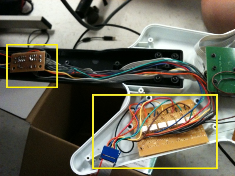
Modified Xbox Guitar Controller:
We had several ways to handle outputting signals back to the Xbox to play the game. Initially we
were planning on outputting a signal to the Xbox directly from our device, but we realized that we
would still need a controller to set up songs. We found that the easiest way to do it was to modify
the Xbox guitar controller to output the signal, while still acting as a functional controller. We
took apart the controller and found that the buttons were simply pressing a conductive surface between
two metal contacts. Instead of taking the buttons out of the controller, we decided to attach switches
to the contacts of the buttons in parallel with the buttons so the controller could still be used as
normal when not being used by the device.
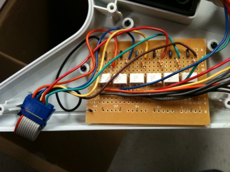
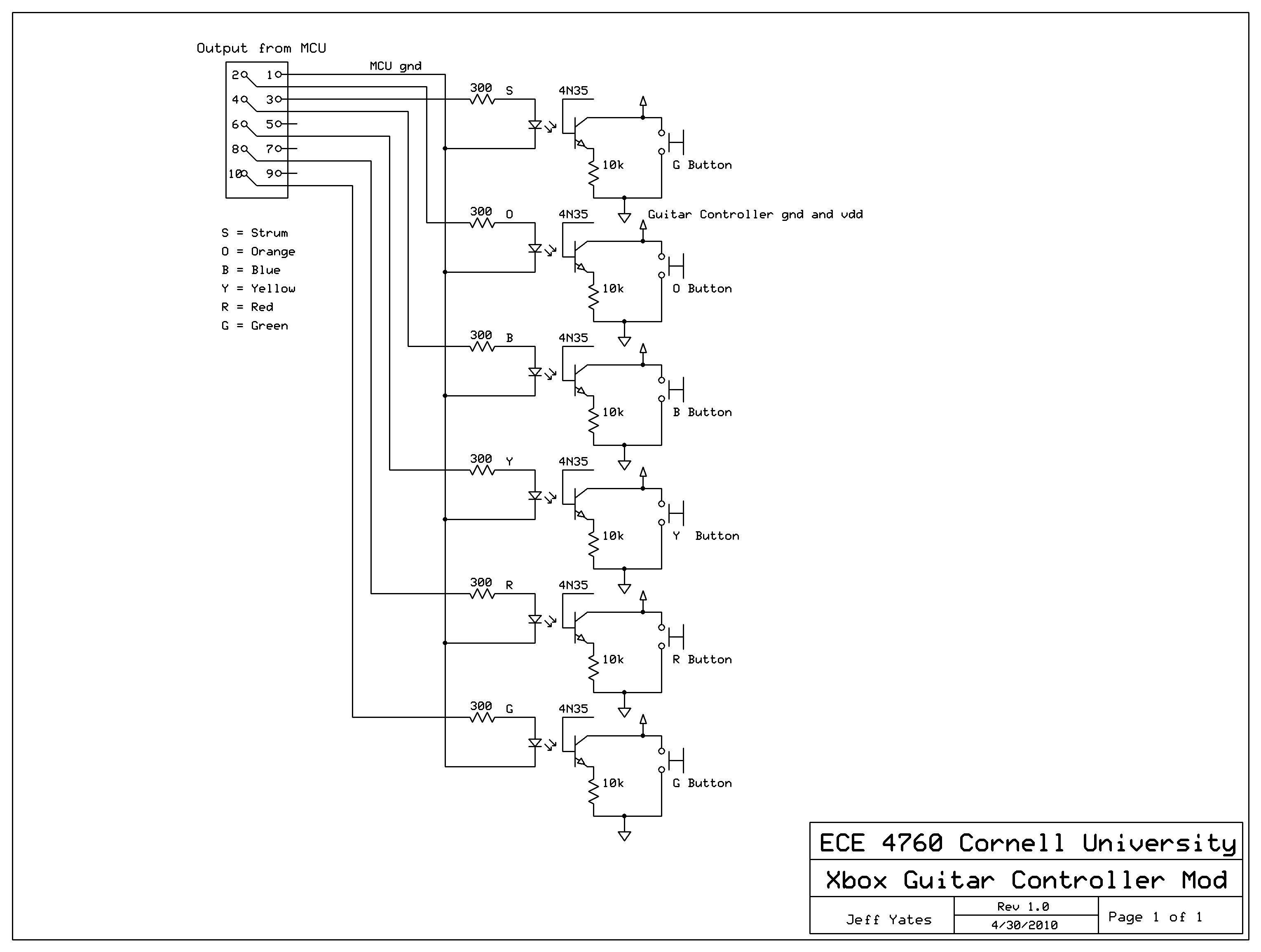
To implement switches across the button contacts controlled by the MCU, we used 4N35 optoisolators driven by the MCU through 300Ω resistors. The other side of the isolator was attached to the two button contacts with a 10kΩ resistor on the guitar ground side of the button. We took this resistor from the optoisolator circuit we implemented in Lab 4, but in retrospect this resistor was not needed. We connected these switches to the existing circuitry by adding in two additional boards into the guitar to hold the switches, resistors, and to connect the existing wires to the new circuitry. For easy connectivity, we wired the input to the guitar switches to a 10-pin ribbon cable. On the MCU side, we wired a 10 pin program header to PORTA to output the signal.
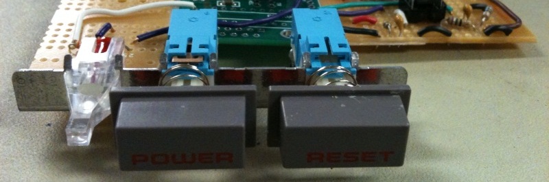
Miscellaneous Hardware:
We also implemented a reset button, power button, and an on LED. The reset button restarts the
entire MCU, and is connected to the custom PCB connecting the reset pin of the MCU to ground through
a 100kΩ resistor. The power button enables the main software loop that detects button pushes and outputs
to the controller. We decided to add this to give us the option of stopping the output of data to the
controller while we were setting up the xbox with the guitar controller. The power button connects
PORTC.5 and PIN C.6, and is used in software. The LED is connected from PORTC.0 to ground through a
330Ω resistor. The LED is controlled in software and goes on when the power button is enabled and the
main loop is running.
[top]
Software Design
External Interrupts:
In order to keep track of the frames and lines from the video signal, we fed the VSYNC and BURST
signals from the LM1881 video sync separator into the external interrupt ports of the microcontroller.
The BURST signal goes low every time there is a new line of video, and the VSYNC signal goes low
every new frame. We feed the BURST signal into the INT0 external interrupt and have an ISR trigger
on every low edge. When the low edge of the BURST signal is detected, we know that there is a new
line and correspondingly increment a lineCount variable that keeps track of the current line being
displayed. We feed the HSYNC signal into the INT1 external interrupt and also have the ISR trigger on
every low edge. When the low edge of the HSYNC signal is detected, we know that there is a new frame
and thus we reset the lineCount variable to 0.
Analog Comparator:
To check if a note needs to be played we use the analog comparator on the Mega644 to compare the
voltage of the low-passed video signal to a set reference voltage. By low-passing the video signal,
we remove the chrominance from the signal leaving only the luminescence. By looking at certain parts
of a line, we can see if there is a bright spot there by looking at the magnitude of the luminescence.
A higher voltage represents a brighter spot while a lower voltage represents a darker spot. We can
thus detect the presence of a note by seeing of the luminescence goes above a reference threshold
voltage. Thus, we input the low-passed video signal into the positive input of the comparator, pin
AIN0, and input the reference threshold voltage into the negative input of the comparator, pin AIN1.
When the video signal voltage is above the reference voltage, the ACO bit of the ACSR register is set
high.
Enable Switch:
In order to enable or disable buttons pushing using a switch, we set PORTC5 to an input and set it
high. We connect this to one side of the switch and connect the other side to ground. If the switch
is closed then PINC5 will be pull low and if it is open PINC5 will be high. Thus we can use PINC5 is
a condition in our main while loop to decide whether to check lines and push buttons or do nothing.
Button Pushing:
We configured PORTA as an output to control the button pushes on the Xbox 360 controller. A high
signal represents a button push while a low signal represents no push. Below is a table representing
the button on the controller and its corresponding pin.
| Xbox360 Button | Corresponding Output Pin |
| Down Strum | PORTA0 |
| Green | PORTA1 |
| Red | PORTA2 |
| Yellow | PORTA3 |
| Blue | PORTA4 |
| Orange | PORTA5 |
Line Checking:
The meat of our code lies within the infinite while loop of the main() function. All the code in
the while loop is incased in an if-statement checking to see if PINC6 is high. This allows us to
control whether or not to push buttons based on the position of a switch. We then check 4 lines
of video per frame for a note to be played. We do this by using an if-statement checking to see if
the lineCount variable matches our desired line. Because the frequency of the microcontroller is much
faster than the update speed of the video, we can expect to enter this conditional block at
approximately the beginning of the desired line.
We also include line check markers to determine if a line had already been checked in that frame. Basically, they are all set to 1 at the beginning of a frame and once a line conditional has been entered, it is set low. Thus no line will be checked more than once per frame.
Inside the conditional block for a line, we the _delay_us() function to check positions of the line where the notes occur. We used an oscilloscope on the video signal to determine exactly how long the delays needed to be to correspond with the maximum height of the luminescence voltage spikes when a note goes by. Below is a table showing the optimum timings that we measured.
| Note Color | Delay From Beginning of Line (μs) | Delay From Previous Position (μs) |
| Green | 20 | 20 |
| Red | 23 | 3 |
| Yellow | 28 | 5 |
| Blue | 32 | 4 |
| Orange | 37 | 5 |
After each delay, we check the ACO bit of the ACSR register to see if the voltage exceeded the threshold voltage. If so, we bit-or PORTA with the corresponding button signal to push the button along with the buttons already pushed. Finally, we set the corresponding line check marker to 0 to prevent that line from being checked again.
After analyzing the signal and looking at the accuracy of our button pushes, we determined best lines to check were lines 199-202. Thus we repeated this process for all four of those lines. For the last line, 202, we end by checking to see if any buttons have been pushing by using an if-statement to check if PORTA is non-zero. If it is, then at least one button has been pushed and we bit-or PORTA with the corresponding strum signal to play the notes. We then delay for 12 ms in order to hold the strum long enough for the Xbox 360 to register the note and to wait until the end of the frame. Finally we reset all the line check markers and reset PORTA to 0x00 to clear all button pushes.
[top]
Development Process
We began our design by doing research and laying out a general schematic of our device. Because we originally wanted to actually analyze the video output data, we wanted something that could decode a composite video signal into a digital signal. We also needed something to strip the HSYNC and VSYNC signals so that we could keep track of the lines and frames. After a bit of research we settled on the TVP5150AM1 video decoder chip. This cheap provided discreet HSYNC and VSYNC signals as well as converted analog composite video into digital video in YCbCr format. Additionally, we were able to sample it for free from Texas Instruments.
Although we planned on creating a separate custom PC board for our microcontroller, we used the STK500 development boards for prototyping purposes. This allowed us to quickly change ports and functionality and gave us access to pushbuttons, LEDs, and UART for debugging.
While we waited for the chip to arrive, we set about modifying the Xbox360 guitar controller to be controlled by the microcontroller. We decided on modifying an existing controller in order to easily conform to the voltage requirements for the Xbox360. All we needed to do was put switches between the buttons that could be controlled through signals from the microcontrollers. This made it so that we could push a button by sending a high signal to the switch. Because the controller has a USB connector, we were able to connect it to a PC and use the Microsoft controller utility to see when buttons are read as pressed. We also wrote a short piece of code that let us set a signal high whenever a push button on the STK500 is pressed. Using this code and the Microsoft utility we were able to debug our hardware. Finally we used a basic 10 pin ribbon cable to extend the connection outside of the guitar case and to allow us to connect the guitar to a port on the microcontroller.
We also needed to find a way to split the composite video signal so use it as an input to our device as well as display it on the TV. We originally thought that a passive splitter would cause the signal to drop too much and cause a significant degradation in the video quality. We thought about amplifying the signal with opamps, but decided to try a passive splitter first. We bought a cheap 2-way RCA splitter and were happy to see that the video did not degrade much at all. We concluded that signal amplification was not necessary for our purposes and a passive splitter would work fine.
When we received the chip, we started to realize that the chip would give us problems, but decided to use it anyways due to a lack of cheap alternatives and time. First of all, the chip came in a TQFP package with a 0.5mm pitch. We realized that even with the steadiest hand, soldering the chip by conventional means would be impossible. After some research we came upon www.schmartboard.com which provided solutions to soldering small surface mounted chips. Their SchmartBoardEZ boards come with grooves corresponding to the pins on the chip. Solder is already placed inside of these grooves so there is no need for any additional solder. In order to solder a chip onto the board, all that we needed to do was run our soldering iron along the groove until it reached the pin. We found that this was remarkably quick and easy, although there was one pin that was very difficult to get a connection on.
Once the chip was soldered into place, we realized that it was not as simple as inputting voltage into one port and getting the signals from another. The chip itself had many requirements to function correctly including a separate crystal oscillator and 3 different types of voltage inputs. Luckily, the datasheet provided an application example which we used as a guide to hook things up. Instead of ordering separate regulators to obtain the different voltage levels needed, we made our own regulators which are basically the same as the one we used to control the reference voltage of our final chip. Although these needed to be periodically adjusted and monitored, they provided a quick and cheap alternative to ordering regulators online.
Once the chip was wired together, we discovered that in order to output the signals we wanted, we needed to program it using an I2C serial connection. Luckily, the Mega644 datasheet provided a good explanation of the Two Wire Interface (TWI) as well as sample code for reading and writing to a slave device. Using the register addresses in the TVP5150AM1 datasheet, we were able to program the registers in the decoder chip to output the HSYNC, VSYNC, and YCbCr outputs from a composite input signal. In this process, we used LEDs on the STK500 to let us know if the video decoder chip had programmed correctly.
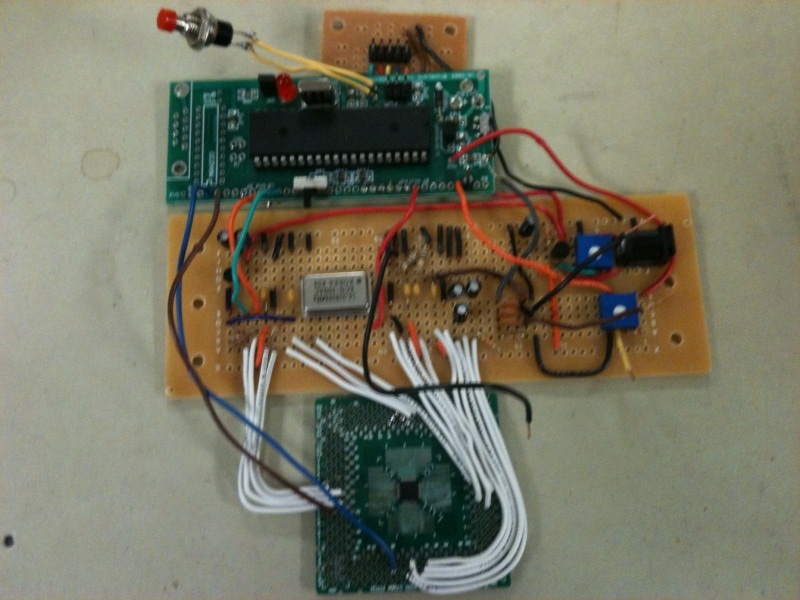
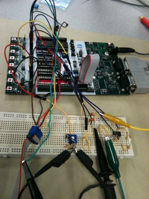
Now that we finally had our video decoder chip set up and programmed, we could test it on actual composite video to see if it worked the way we wanted. We used the output of a Playstation 2 slim to test our chip mainly because of its ease of transport to and from the lab. Initially, we were hopeful because the HSYNC and VSYNC signals were being outputted correctly. However, when we started to analyze the digital video output data, we realized that we have made a grievous error. Originally we thought that the YCbCr encoding stored the data for one pixel per byte. Thus we would simply sample the output of the decoder chip to get pixel data at the point that we wanted. This turned out to not be the case. In fact, YCbCr encodes pixels in 4 byte chunks. The encoding that our video decoder chip was outputting, YCbCr 4:2:2, sends the data for two pixels in every 4 bytes. Two of the bytes represent the luminescence of two consecutive pixels while the two chrominance values are stored in the other two bytes. Both pixels share the chrominance values while having individual luminescence values. This may not have been such a big problem except for the fact that the decoder chip outputted this data at a rate of 27.0MHz. Because our microcontroller only has a clock speed of 16MHz, there was not easy way to sample 4 consecutive bytes of data in order to analyze individual pixels. A picture of our first design is shown below.
After a day of frantically searching for a solution and weighing our options, we stumbled upon www.autoguitarhero.com in which someone implemented a similar device for Guitar Hero on the Wii console. Instead of analyzing the video output pixel by pixel for color and brightness, he simply used an analog comparator to check the voltage of the video signal against a reference voltage at certain parts of the video. Because notes are brighter than the background, a passing note would trigger the comparator signaling for a note to be pressed. Although this was not our original design, it provided an easy alternative method that we could use to play the game. Because our resources were stretched and our time was running out, we did not have time to do research on a new chip, order it, and put it together before the deadline. Additionally, the Mega644 microcontroller already has a fast analog comparator onboard so we would be able to get started immediately.
The hardware to set this up was considerably easier than setting up the video decoder. In order to only get the luminescence of the composite video signal, we used a low-pass filter to strip away the chrominance sub-carrier frequency. We then created an adjustable voltage regulator so that we could adjust the threshold voltage using a trimpot. We tested this method on a basic menu screen on a PS2 game in which we could toggle a bright white arrow up and down. We then used the TDS 1012B Oscilloscopes in the lab to look at the video signal. These oscilloscopes have the ability to sync the trigger with NTSC video and examine the signal line by line. We scrolled through the lines on the scope until we found a point where the brightness went high whenever the arrow was moved. We then scoped the comparator output to confirm that it was working properly.
Now that we knew that this method would work, we set it up on the actual Xbox360 output of the Rock Band game. Using the scope, we were able to find the line on the screen right before the notes needed to be played. We then used microsecond delays from the start of the line to check the comparator at the points where the notes would pass through. We adjusted these timings by looking at the scope and finding where the brightness peaked.
We started by only checking and playing one button and eventually progressed to pushing them all, adjusting the timings as needed. The initial performance was passable, but was plagued by missed notes and false triggers. We found that the best way to relieve some of the false triggers was to insert a delay after the buttons are pushed so that the line would not be checked multiple times a frame. To increase accuracy, we decided to check multiple lines instead of only one. These measures helped drastically, allowing us to complete the hardest songs on the hardest difficulty with accuracy at the mid 90% mark. Nevertheless, we strove for our final goal of 100% accuracy. We played with multiple variables such as line position, interval timings, and checking multiple points per line for a single note, but all of these efforts led to decreased accuracy. In the end, we found that our simple model worked best.
Although our project now worked, it only really worked some of the time. Often, for inexplicable reasons, the decoder chip would not program or would program but not output SYNC data. Often the best way we could resolve this problem would be to shake the board until something happened. We tried to scope certain connections to look for a short but found nothing that would cause the problem. Additionally, all the voltages and additional hardware was creating noise on the video signal and reference voltage. This was adding additional uncertainty into our program. We eventually realized that this was not acceptable and decided to scrap the entire video decoder chip and use a simple video sync separator, LM1881, used by the man who created www.autoguitarhero.com. This chip vastly reduced the hardware complexity of our design and also reduced noise. Most importantly our device became stable and worked predictably.
Finally, to cap it off, we decided to add an enable button so that we could navigate menus without the device randomly pushing buttons.
[top]
Results
Speed of Execution:
The speed of our device matched our requirements and expectations. As expected, our microcontroller
was fast enough to pinpoint specific points in each line to check for the presence of a note. Our analog
comparator also worked within the timing requirements allowing us to get accurate comparisons
immediately. Additionally our controller modification was extremely responsive, allowing us to signal
button pushes on the fly. Furthermore, by adjusting the position of the line that we check for a note,
we were able to get our device to play virtually every song and every difficulty fairly accurately.
Accuracy:
Overall the accuracy of our device is quite good. Below is a table showing the scores that it got on
several songs.
| Song Name | Classification | Difficulty | Accuracy (%) |
| B.Y.O.B. | Nightmare | Expert | 98 |
| B.Y.O.B. | Nightmare | Medium | 96 |
| Chop Suey | Nightmare | Expert | 94 |
| Chop Suey | Nightmare | Medium | 96 |
| Carry On My Wayward Son | Nightmare | Expert | 98 |
| Carry On My Wayward Son | Nightmare | Medium | 97 |
| Painkiller | Impossible | Expert | 95 |
| Painkiller | Impossible | Medium | 96 |
| Panic Attack | Impossible | Expert | 98 |
| Panic Attack | Impossible | Medium | 97 |
| Bodhisattva | Impossible | Expert | 96 |
| Bodhisattva | Impossible | Medium | 98 |
| Everlong | Challenging | Expert | 97 |
| Everlong | Challenging | Medium | 96 |
| Don’t Stop Believing | Moderate | Expert | 98 |
| Don’t Stop Believing | Moderate | Medium | 98 |
| Should I Stay or Should I Go | Warm up | Expert | 96 |
| Should I Stay or Should I Go | Warm up | Medium | 98 |
We found that our device worked better on faster songs due to the nature of the timing. Because we check for a note slightly before we play it, our device sometimes hits notes on slow songs too early. By adjusting our line position, we were able to mitigate most of these effects. Also, our device worked better on individual notes and struggled more on chords. This is because in order to hit a chord multiple buttons need to be pressed and if any additional buttons are pressed the chord does not register.
Although the note accuracy is good, we have a bigger problem with false triggers. Often a note is played more times than it needs to be causing an error and resetting the point multiplier. This is especially true for the sustain notes. Currently, we do not hold down the note for the sustain; however, because the sustain bar lights up when the note is pressed, our microcontroller thinks that there is another note after it and false triggers.
We found that with multiple runs of the same song, we have slight variation in the accuracy of our device. This is probably due to noise in the video signal as well as timing inaccuracies in the microcontroller. Nevertheless, the accuracy only varied by a few percentage points either way.
Note that all of our trials were done in the training mode. This is because training mode has a static background while normal mode can have a lot of light interference from the background. Even so, our device can still do quite well, just with slightly reduced accuracy. Other factors of normal mode that reduce accuracy are the star power notes. Every time all the star power notes are hit in succession, the screen flashes causing a false trigger. Additionally, if star power is actually activated by the user, the background becomes very bright, creating more false triggers.
Interference:
Signal noise can influence the accuracy of our device. Although the impact is minimal on the performance,
we have noticed on the oscilloscope that signals from the Dremel tool being used have influenced our
video signals. Furthermore, variation in the accuracy on the same song can be partly attributed to generic
interference from the environment.
Usability:
Our device is very user friendly. Its size is small and we have ports to connect the power, video, and
modified Xbox controller quickly and easily. Because our modified controller is still usable on the
Xbox360, there is no need to connect multiple controllers. Our enable switch allows the user to navigate
menus without the controller pushing random buttons. It even has an indicator LED that lets you know when
the device is functioning.
The only real issue with usability has to do with the reference voltage for the comparator. Because it is controlled by an adjustable regulator, it could vary from its set value if it is bumped or adjusted. In order to set it back to our recommended setting of 520mV, the user would need a multimeter or oscilloscope to determine the current voltage setting.
[top]
Conclusions
Meeting Expectations:
Overall, our automated Rock Band player met our expectations for this project. We set intermittent
goals along our design process, striving for just one note to playing entire songs, and we met them
all. Although we had a theoretical goal of 100% accuracy, realistically we hoped for something in
the 90% range. On this front, we succeeded quite well. On even the hardest songs in the game on the
hardest difficulty, we managed consistently in the mid to high 90%s. The one thing that we were a
little disappointed with was the ability to maintain note streaks. Due to noise in the signal, we
had significant false triggers of notes which counts as an error in the game and resets the streak
multiplier. Although we tried many options to remedy this problem, they all came at a cost of
accuracy. In the end, we decided that for the scope of this project we would focus on accuracy
rather than note streaks.
We also set some other goals that we were willing to try if we completed this project early. Unfortunately we did not have time to implement these features. They included the ability to hit sustains, the use of star power, support for multiple players, and the ability to play drum parts. Although these features would have been nice, they were not essential to the function or enjoyment of our project. If we had more time we probably could have implemented most of these features without too much extra work.
If we were to make a revision of this project, we would probably first try to improve the signal. This could be done by amplifying the signal going into the comparator. Also, we could use a separate threshold level for each note. In looking at the scope, we saw that different color notes have different average peak amplitudes. Using different thresholds for each note would probably greatly improve accuracy. On the software side, we could probably try to implement some sort of debounce system for the buttons. Although we tried in this lab, the accuracy fell too much for it to be worth it. If we could increase the accuracy on the hardware side, it would give us more leeway to play with the scanning code. One way that we experimented with debounce was to not allow the same note to be played for a certain amount of frames. When the system was accurate this worked quite well. We could also implement the ability to play sustain notes. This would probably involve holding down all notes after they are played until the next note is played. We would also have to shift our detection region slightly to the sides of the note in order to avoid picking up the bright sustain bar that follows a sustain note. This would allow us to hold the note down but not trigger a false strum.
The main issue that we probably had was a lack of preparation and research. We felt rushed to begin our project and as result obtained a chip that didn’t really meet our purposes. This was also partly due to the fact that we did not fully understand the capabilities of our microcontroller. The chip we got was very hard to mount, required a lot of additional hardware, and outputted digital video too fast for our microcontroller to process. Also, we misinterpreted how YCbCr digital video output was represented. We thought that each pixel was represented by one bit, but we later found out that each pixel was encoded in about two bits of data. If we had known this from the beginning, we probably would have tried a different approach.
Standards:
The main standards involved in our project were NTSC and the Xbox360. For NTSC, we used a decoder
chip to pull out the SYNC signals out of the video signal. Because we did not output any video, we
did not have to format anything into NTSC standard. To avoid conforming with the standards of the
Xbox360, we simply used a modified Xbox360 controller. We used switches to short the button leads
together allowing the controller to remain intact and function normally according the Xbox360
standards.
Ethical Considerations
We constructed our project in accordance to the IEEE code of ethics. Our project does not pose
any safety or health concerns that we know of. Our device is small and does not contain any
significant electrical hazards. As for the game itself, because there is virtually no human
interaction, it poses no more risk than the original game. Our project does not discriminate
against and race or religion and is even accessible to handicapped people. To our knowledge, we
are not violating any laws or regulations. We do not claim the Xbox 360, the Xbox guitar
controller, or Rock Band to be our own design. We simply made basic modifications in order to
control them using our microcontroller.
One consideration to note is that our device cannot be used online via Xbox Live. Because our device is an automated player, it violates the Xbox Live terms of use agreement. Thus it is important that nobody uses our project to falsely represent their own abilities online. Although our device probably wouldn’t score among the top players online, it would still be a false representation of one’s abilities. It is also advised not to use this device to exaggerate one’s own abilities offline. Although it does not violate any terms of use agreements, it would be unethical to falsely represent one’s skill.
[top]
Appendix A: Photos and Videos
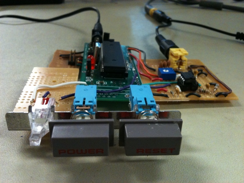
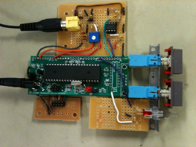
Final design photos:
- Full circuit image 1
- Full circuit image 2
- Full circuit image 3
- Solder board close up
- Using the STK500 for testing
- Guitar modification
- Guitar optoisolator circuitry
Videos:
[top]
Appendix B: Our Code
[top]
Appendix C: Schematics
![[First Revision] Main Schematic](rev1_main.bmp)
[top]
Appendix D: Cost Details
| Component | Part # | Source | Cost | Qty. |
| Mega644 | Lab | $8.00 | 1 | |
| Custom PC Board | Lab | $4.00 | 1 | |
| Power Supply | Lab | $5.00 | 1 | |
| Solder Board (6 inch) | Lab | $2.50 | 2 | |
| RCA Y-Splitter | Radio Shack | $4.00 | 1 | |
| 10 Pin Flat Ribbon Cable | Lab | $0.00 | 1 | |
| Phototransistor Optocoupler | 4N35 | Lab | $0.00 | 6 |
| Video Sync Separator | LM1881 | National Semiconductor | $0.00 | 1 |
| RCA Plug | Lab | $0.00 | 1 | |
| Xbox 360 | Previously Owned | $0.00 | 1 | |
| Xbox Wired Guitar Controller | Previously Owned | $0.00 | 1 | |
| Color TV | Lab | $10.00 | 1 | |
| Header Plug | Lab | $0.05 | 12 |
Total Cost: $36.60
[top]
Appendix E: Task Breakdown
| Task | Contributor |
| Software Design | Both |
| Hardware Design | Both |
| Custom PCB | Jeff |
| Controller | Jeff |
| Sync Stripper | Jeff |
| Low Pass Filtering | Jeff |
| Interfacing Hardware | Both |
| Hsync/Vsync external interrupt routines | Li |
| Main decoding loop | Li |
| Video timing analysis/tuning | Li |
| Testing/Debugging | Both |
| Previous Design: | |
| Serial Communication | Jeff |
| Decoder Chip Implementation | Jeff |
| Power regulators | Jeff |
[top]
References
Datasheets:
Vendor Sites:
Code/Designs Borrowed From Others
- Michael Seedman's FPGA Guitar Hero player on www.autoguitarhero.com
Background Sites/Papers
- Wikipedia's page on NTSC standard video format
[top]
Special Thanks
The following people and companies helped make this project possible and deserve special thanks:
- Texas Instruments for samples of the TVP5150AM1 video decoder chips used in our initial design
- National Semiconductor for samples of the LM1881 Video Sync Stripper chips
- Michael Seedman of www.autoguitarhero.com for his inspiring design
- The TAs of ECE 4760 Spring 2010 for fielding our questions and keeping the lab open for some pretty marathon stretches
- Bruce Land. Bruce has a wealth of knowledge and helped us out greatly during every step of this project. He made our project and the Cornell ECE 4760 course possible.