Introduction
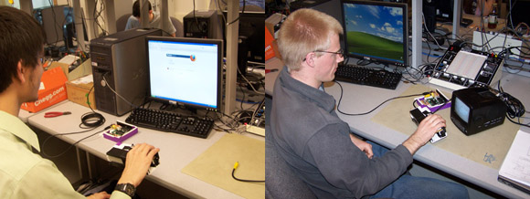
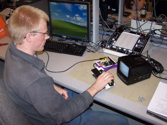
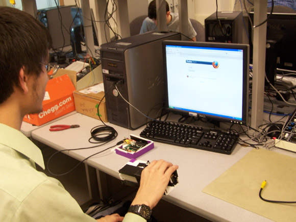
We created a handheld mouse device that measures its tilt and then wirelessly transmits the data to a base unit, which is connected to a PC through a USB cable and can be recognized by certain modern computers as an actual mouse.
The purpose of this project was to explore the possibility of creating a wireless mouse that could be used in any location without having a flat surface to move it on. For this reason, we created a handheld device that uses accelerometers to detect its own orientation a feature that can be controlled by a user's arm movements alone. We made the device transmit data wirelessly to a base station so that there would not need to be any wires connecting the handheld device to the computer it controls, which would limit range and comfort when using the mouse from a distance.
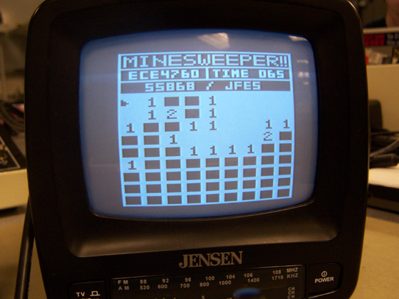
We later discovered we had an excess of computing power in our base unit, so we added an extra mode of operation by which the base unit could be connected to an analog TV via an RCA cable, and the user could play a game of Minesweeper using the wireless mouse.
High Level Design
Rationale
The ideal device we had in mind was one that a user could control with simple arm movements without necessarily having to be sitting at the desk or other flat surface where the computer is located. This kind of device could be used for controlling a computer while giving presentations, or while located on the opposite side of a small room without having to relocate oneself toward the computer. We were inspired to combine features of several previous ECE 4760 mouse-related projects.
First, there was an accelerometer-based mouse by Karthikeyan Muthuswamy and Aseem Kohli, who described the idea as "cool" and hypothesized that it may reduce the risk of carpal tunnel syndrome by reducing pressure on the median nerve (see the National Institute of Neurological Disorders and Stroke fact sheet for more information).
Second, there was an easy input head-controlled keyboard and mouse project by Sara Xiangrong Huang, Jesse McMullen, and "Frank" Wai Shing Wong. This project used a wireless transmitter and receiver to relay information from a measurement unit to a base unit connected to a computer. We decided it was a good idea to separate our own project into handheld and base units to improve ease-of-use.
Third, there was a USB magnetic mouse project by Yiyin Ma and Abby Lin. From this project, we were inspired to have the base unit communicate with the computer over a USB cable, because USB ports are a very common feature on modern computers, whereas PS/2 ports are becoming increasingly rare.
The decision for implementing a Minesweeper game on the base unit was a result of an excess of computing power, to be discussed in the hardware design section.
Background Math
Figure 2 demonstrates how accelerometers can be used to measure the tilt of a device.
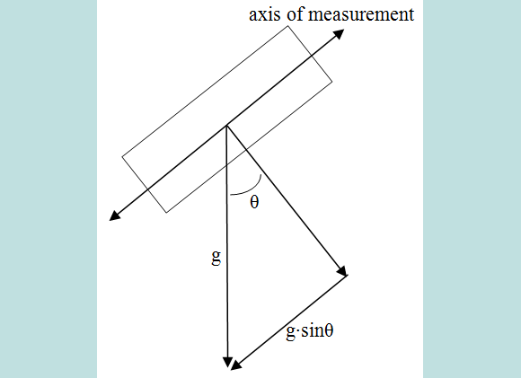
Suppose a 1D accelerometer is represented by the rectangle. It can measure acceleration, either positive or negative, along one axis. If the accelerometer is tilted by an angle relative to vertical, then the acceleration it would experience due to the force of gravity is proportional to the sine of that angle. Thus, increasing the angle of tilt up to 90 degrees relative to vertical will increase the magnitude of the measured acceleration. As long as the accelerometer can detect accelerations up to 1g, it can measure the magnitude of tilt experienced by the handheld device in one direction. By placing two accelerometers positioned orthogonally on the handheld device, it is possible to measure the tilt of the device in two directions (corresponding to x and y mouse movements).
Logical Structure
The high-level logical structure is represented in Figure 3. It shows the flow of information, from when data is first collected by accelerometers, to when it is sent to the computer or TV.
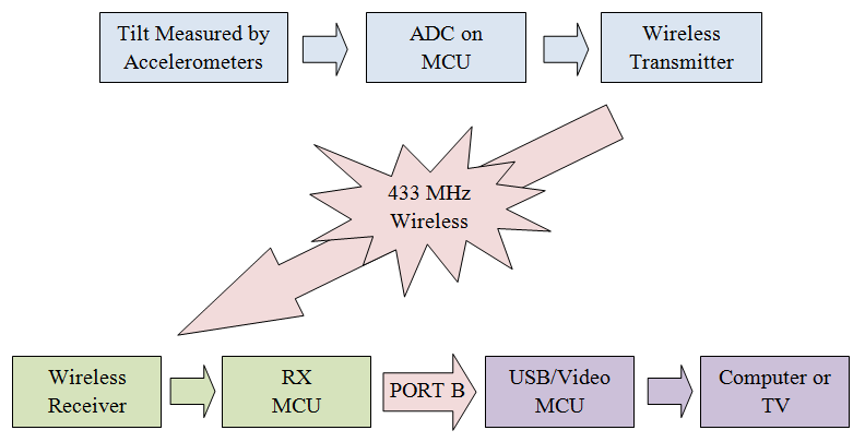
The blue boxes at the top of the figure represent the handheld, or transmitting, unit. Tilt information is measured by accelerometers on this unit, which export analog voltages. These voltages are converted into digital signals by the Analog-to-Digital Converter (ADC) of a microcontroller (MCU), which will be referred to as the TX MCU hereafter. The TX MCU computes mouse status information from the measured accelerations and pushbutton status. This status information is sent as digital signals to a wireless transmitter, which then sends a 433.92MHz wireless signal to a mechanically isolated base station, represented by the four boxes at the bottom of Figure 3. A wireless receiver in the base station receives the signal and sends it as digital output to a microcontroller, hereafter referred to as the RX MCU. The RX MCU then relays the message to a second microcontroller on the base station, hereafter referred to as the USB MCU, which then interprets the mouse status information. Depending on the mode of operation of the USB MCU (either USB mode or TV mode), it may interpret the status differently before sending it over a USB cable or RCA cable to a computer or TV respectively.
When in TV mode, the USB MCU must do more than simply relay data. It must also manage the game. Minesweeper is a game in which a 9x9 grid of tiles are initialized so that ten of them have a buried mine underneath. To win, a player must click all the tiles that do not have mines, until only ten tiles are left. After a tile is clicked, one of three effects may happen. If the tile has a mine, the player loses, and the locations of all mines on the field are revealed. If the tile does not have a mine but there is at least one mine in the neighboring tiles (there are up to eight neighbors in a 3x3 square around the clicked tile), then the tile is replaced by a number indicating how many of its neighbors have mines. If the tile does not have a mine, nor any neighbors that have a mine, it is replaced by a blank square, and a cascade begins. In a cascade, all tiles without mines that can be reached from the clicked tile by taking unit steps in the up, down, left, or right direction and stopping at the first non-blank square are automatically clicked. If the player wins, the locations of all mines are indicated with a flag symbol. If at any time during the game, the player believes a tile to hold a mine, a right-click of the mouse can be used to place a tentative flag on that tile, preventing the player from left-clicking it. The flag can be removed with another right-click. The game also features a second timer, which acts as a scoring mechanism, as dedicated players may wish to complete the game as fast as possible.
Hardware/Software Tradeoffs
The USB interface was implemented using an Atmel ATmega644 microcontroller in software instead of buying a dedicated hardware USB IC. This decision was made early in our design process when we thought to have a single microcontroller handle the base unit operations of decoding input from the wireless receiver and sending it to a computer through USB. Most USB IC components we researched converted from one data protocol (SPI or USART) to a USB protocol. However, the wireless receiver communicates with the microcontroller through its only USART input, and we perceived it to be cleaner and easier to implement the USB interface directly on the microcontroller based on pre-existing code, rather than introduce an extra communication protocol. As a consequence, the USB communication operations took precedence on the microcontroller, eventually leading to the split of the base station work between an RX MCU and USB MCU. So, at the benefit of directly controlling the USB communication and being able to leverage pre-existing code, our design requires two microcontrollers on the base unit, which is an area, power, and cost overhead. As a potential improvement, an SPI-to-USB IC may be more beneficial.
Standards and Trademarks
Wireless
The wireless transmitter and receiver operate using On-Off Keying (OOK) modulation at 433.92MHz. When transmitting a logical 0, no signal is sent. When transmitting a logical 1, a 433.92MHz wave is sent. Transmissions are sent approximately 58.8 times per second. The relevant FCC regulations for low power transmitters operating in the radio frequency range greater than 70MHz (and specifically between 433.5MHz and 434.5MHz), transmitting periodically, can be found in Title 47 CFR 15.231 and 15.240. These frequencies are reserved for alarm systems, door openers, remote switches, etc., and it is not permissible to transmit at regular predetermined intervals. Specifically, the wireless range from 433.5MHz to 434.5MHz is restricted to devices that use radio frequency energy to identify the contents of commercial shipping containers. Since our device is a computer mouse, it does not fall into either of these categories. Although we were unaware of it at the time it was built, our design is in violation of the wireless FCC regulations. Any future work relating to this design will have to replace the transmitter with a device using a different frequency.
USB
"USB" and all associated logos and related terms are registered trademarks. We do not claim that our device is USB compliant. At most, we have observed that certain computers have recognized our device as a mouse over a USB cable. We have not entered into any agreement to receive our own USB Vendor or Product ID for this device. Instead, it makes use of a pre-existing Vendor ID and Product ID combination for a common mouse device. This operation does not infringe upon any laws.
Our circuit may not meet physical requirements specified by the USB standard (notably 3.3V signals and a 1.5kOhm pull-up resistor). A USB cable contains four wires a 5V Vcc wire, a D- wire, a D+ wire, and a gnd wire. Data is transmitted bi-directionally across the cable using differential signals on the D+ and D- lines. That is, D+ is at 3.3V and D- is at 0V to transmit a logic high, and D+ is at 0V and D- is at 3.3V to transmit a logic low. When a USB device is first connected to a computer, it must hold either D+ or D- at 3.3V through a 1.5kOhm pull-up resistor in order to indicate a desired connection speed of either 12Mbps or 1.5Mbps, respectively. At most, we have observed that our circuit operates sufficiently close so that certain computers have interpreted the transmitted signals as intended.
NTSC
We do not claim that our device meets NTSC standards. However, our device outputs a video signal that is similar to the NTSC protocol, and we have observed that certain analog TVs have been able to interpret the transmitted signal as intended over an RCA cable. The signal consists of three output voltages of approximately 0V for sync, 0.3V for logic low, and 1.1V for logic high. Each digit sent to the TV is one of these three voltages, held for 0.25us or longer. A logic high or low digit represents an instruction to draw a white or black pixel to the screen, while a sync digit represents an instruction to start a new line or new frame depending on the length of the sync command. A long sync instructs the TV to start drawing a new frame from the top-left of the screen. Afterwards, each high or low digit will be transcribed to the screen from left to right until another sync is encountered. A short sync instructs the TV to start drawing at the beginning of the next line, at the left of the screen. This procedure of drawing lines is repeated until the TV reaches the next long sync. We send a video signal of 262 lines to the TV of 144 pixels each, but only 200 of the lines contain actual pixel information (the rest are blank logic low). A line is drawn every 63.625us, and with 262 lines per frame, a frame is drawn at approximately 59.99Hz.
Design
There have been no patents for the hardware design we used. The Minesweeper game concept is not copyrighted, and our software implementation was made entirely by ourselves. The code obtained from V-USB is distributed under the terms of the GNU General Public License (GPL) version 2 and the GNU General Public License (GPL) version 3.
Hardware Design
All hardware schematics can be found in Appendix C: Hardware Schematics.
ECE 4760 Custom PCB
To interface the ATmega644 microcontroller with external circuitry, we used the ECE 4760 custom printed circuit board (PCB). The actual printed circuit design is shown in Figure 4, and an example of an older version of the board with surface and through-hole components attached is shown in Figure 5.
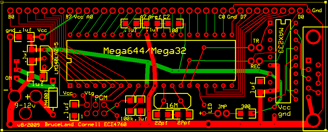
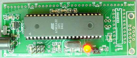
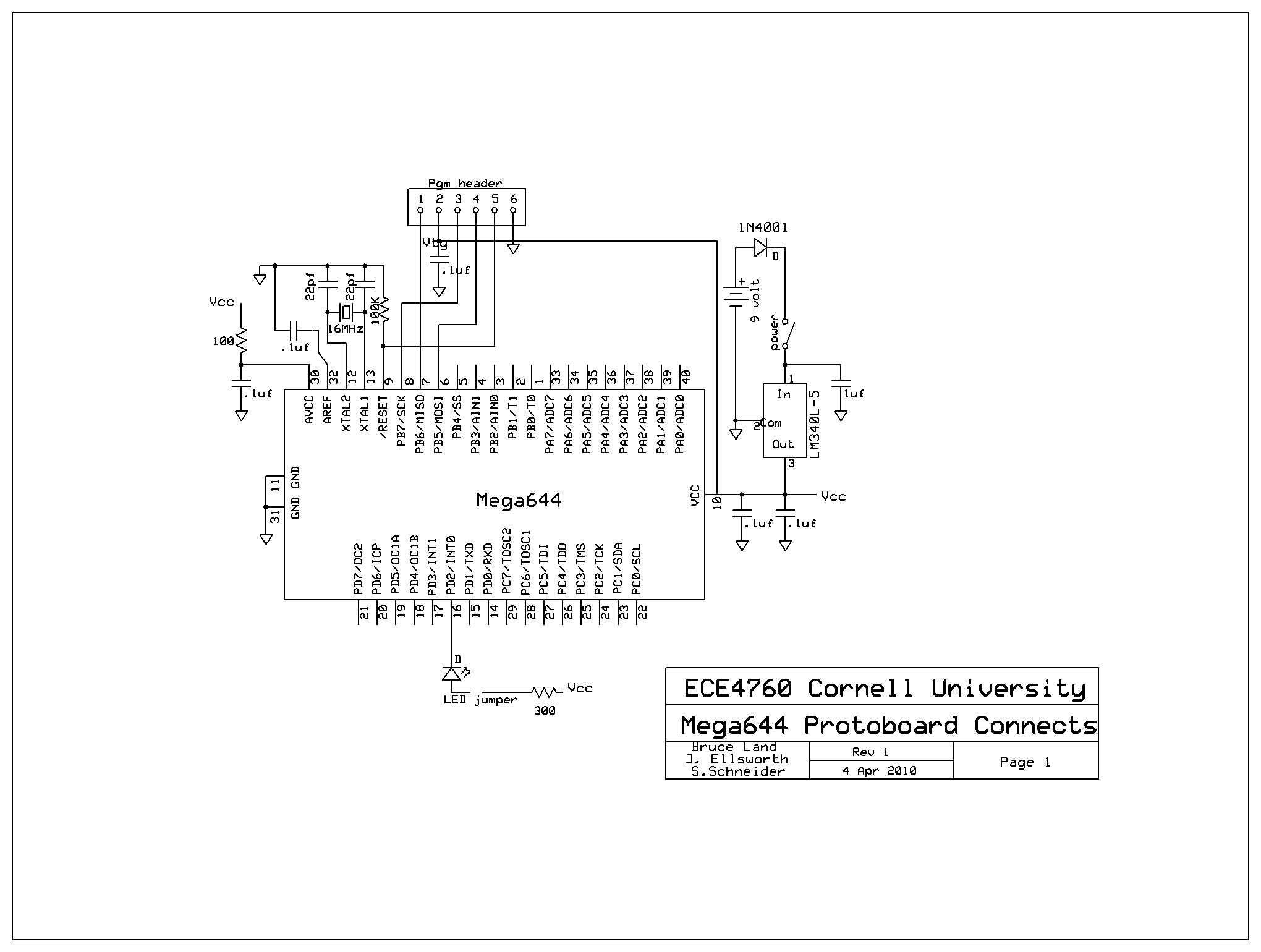
This board uses a National Semiconductor LM340LAZ-5.0 power regulator to convert an external 9V power supply into a 5V Vcc signal. It routes power and ground signals to a mounted ATmega644 or ATmega32 microcontroller. A switch connected to the left side of the board can be used to turn power on or off. A 16MHz crystal is used to generate the microcontroller's clock. A six-pin programming (PGM) port is used to program the software on the microcontroller. Optionally, an LED can be connected from pin D.2 to gnd. Not present on the older board shown in Figure 5 are a 1N4001 diode used to protect the power regulator from reverse bias, and a Vcc hole located close to the Vtg pin of the PGM port for easy bridging. A summary of the connections we used in shown in the schematic in Figure 6.
All three of our microcontrollers are ATmega644s mounted on a custom PCB. Present on all of them are the 16MHz crystal and the six-pin programming port, including the wired bridge from Vcc to Vtg. Also present are all surface-mount resistors and capacitors. However, base unit PCBs may exclude the power regulator or LED circuitry as discussed later.
Transmitting Unit
Disclaimer: The following design is not FCC compliant. Any future work based on this design should use a different wireless transmitter.
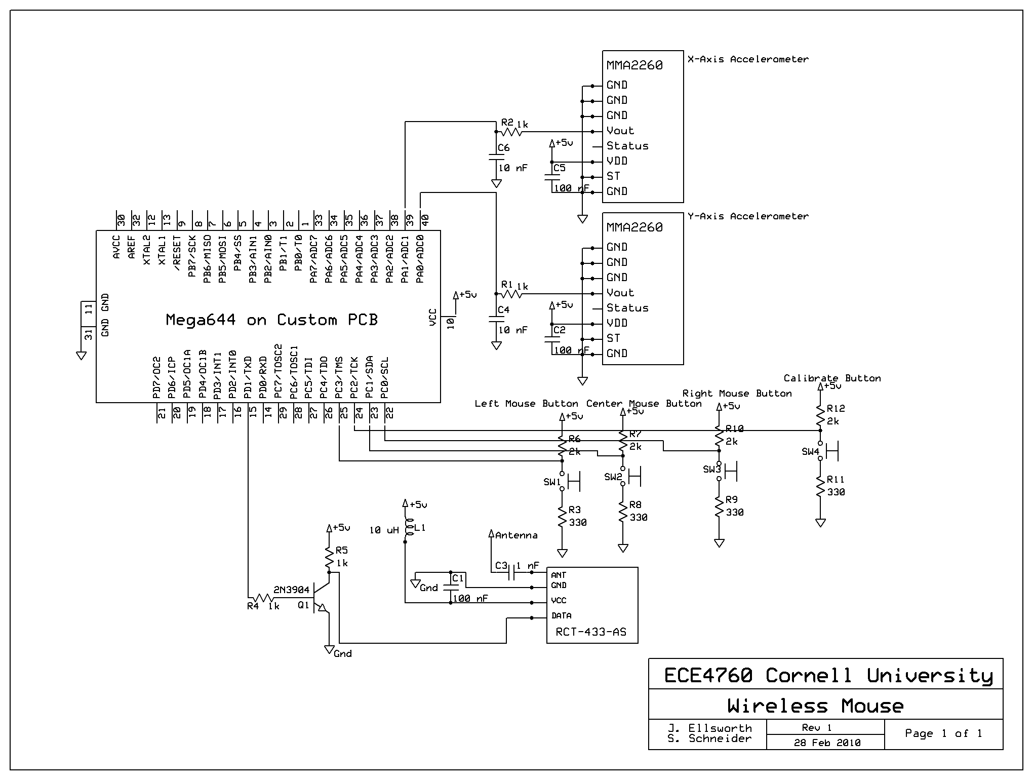
The hardware schematic for the handheld mouse unit is shown in Figure 7. It consists of two single-axis accelerometers, an ATmega644 microcontroller on custom PCB, a wireless transmitter, and four pushbuttons. The accelerometers are Freescale Semiconductor MMA2260D chips. They are single-axis ±1.5g accelerometers that produce a voltage that is centered near 2.5V for an acceleration of 0g and that increases or decreases around this point based on positive or negative acceleration along the axis of measurement. When low-passed, the output can be considered a continuous analog signal that does not require any control commands to compute. This analog voltage is fed into the ADC on the microcontroller. The y-axis accelerometer is connected to pin A.0 and the x-axis accelerometer is connected to pin A.1.
A Radiotronix RCT-433-AS wireless transmitter is used to transmit the mouse data to the base unit. The circuit is the one suggested by Meghan Desai in his wireless project. Its power and ground pins have an external inductor and capacitor to low pass filter any noise that would be near the 433.92MHz transmit frequency and to prevent fluctuations in the Vcc voltage as a result of wireless transactions. The antenna pin of the transmitter is connected to a 19-cm wire (the antenna) through a series capacitor to high-pass the 433.92MHz signal and block out DC voltage. The data input to the transmitter is fed from the USART TX pin (D.1) on the microcontroller. The data from the microcontroller is inverted using a transistor because a logic high output from the USART is the normal state, and we do not want to waste power by transmitting a logical 1 when no data is being sent.
The pushbuttons are fed into pins C.0 through C.3. Ideally, the pins are normally tied to Vcc through an external pull-up resistor but when the button is pushed it connects the pin through a smaller resistor to gnd, which pulls the input low. However, two of the buttons had a reverse behavior (when the buttons are unpushed, the circuit is closed, and when the buttons are pushed, the circuit is open), so their behavior was corrected in software. Three of the buttons are used for the left, middle, and right mouse buttons. The fourth button is a calibration button that will zero the acceleration when it is pushed.
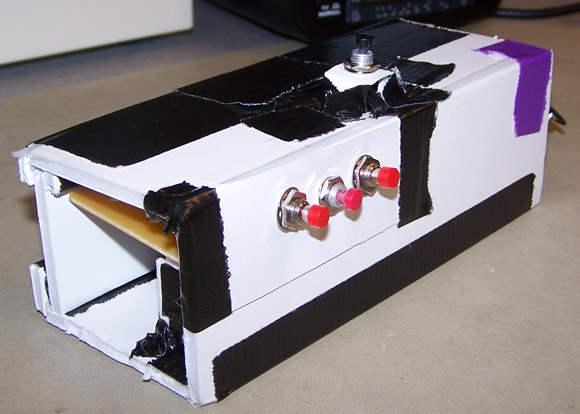
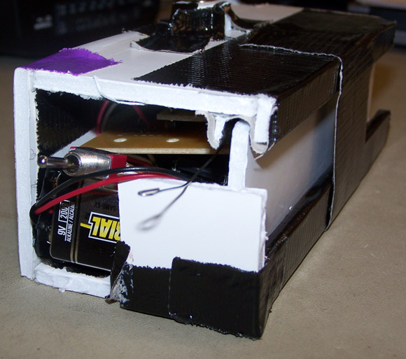
The entire handheld unit, including accelerometers and wireless transmitter, is powered by a 9V battery fed directly into the 5V regulator on the custom PC board for the microcontroller. A switch was connected to the custom PCB to allow the device to be turned off to conserve the battery when not in use. An LED was connected to pin D.2 to indicate when the device is powered. The accelerometers and wireless transmitter are mounted on a separate solder board. Everything fits nicely into a compact handheld box that was made from a foamboard. Photos are shown in Appendix A: Photographs.
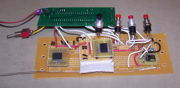
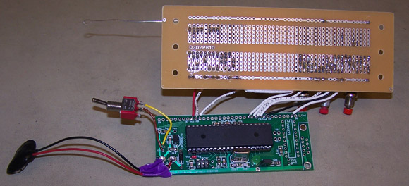
Base Unit
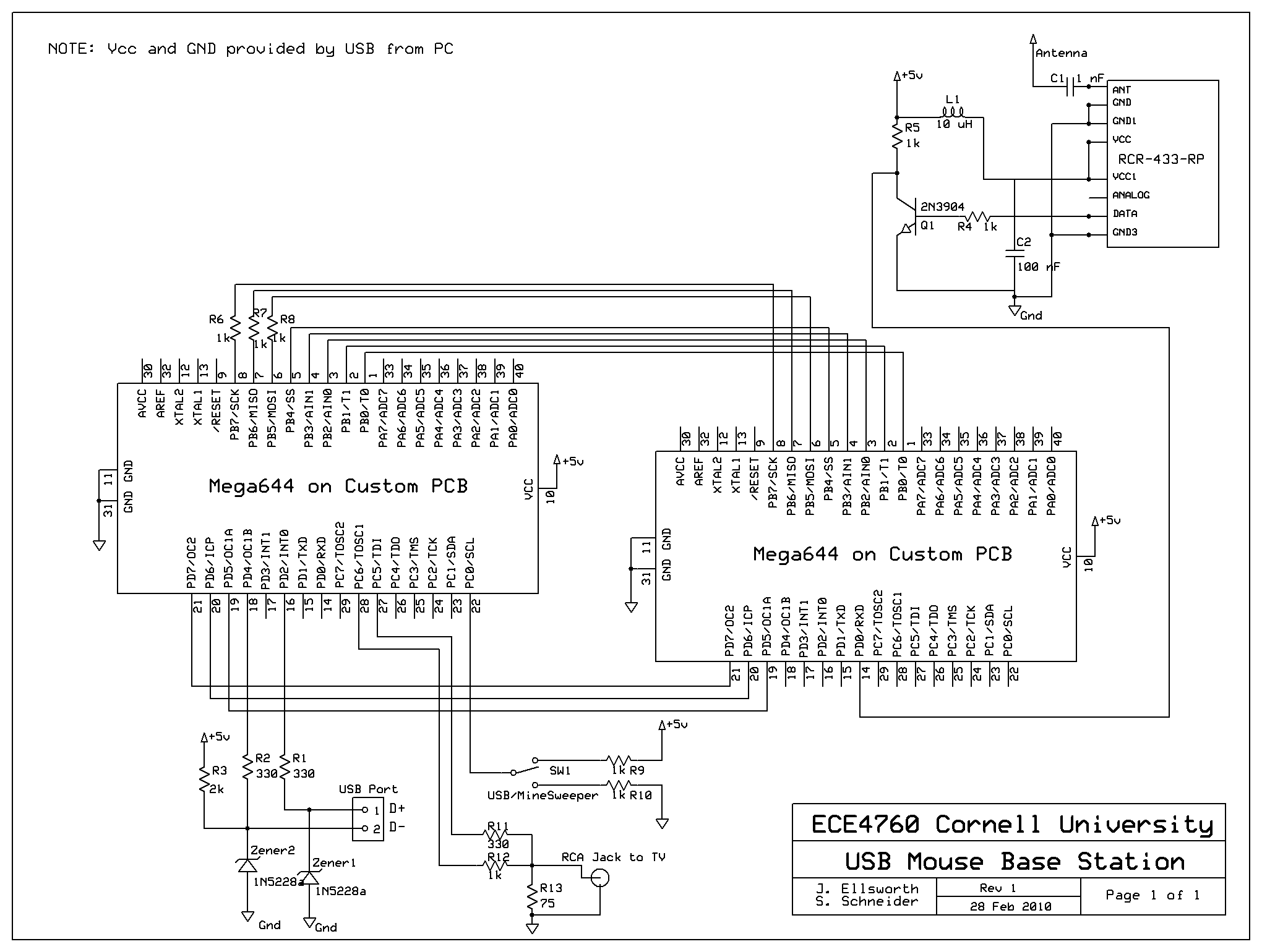
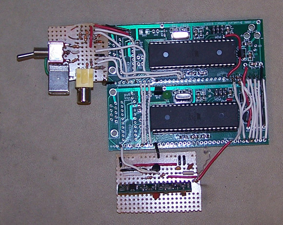
The hardware schematic for the base unit is shown in Figure 8. It consists of two ATmega644 microcontrollers, a wireless receiver, USB circuitry, video circuitry, and a switch for choosing between USB mode and TV mode. The RX MCU, shown at the right of Figure 8, receives data from the wireless receiver, and the USB MCU, shown at the left, either transmits that data to the PC through USB or uses the data to control the Minesweeper game video signal through an RCA cable. The two microcontrollers communicate with each other using port B and the upper three pins from port D. A custom communications protocol was created to allow the two microcontrollers to communicate. See the software section for an explanation. 1kOhm resistors were added between the top three port B pins because those three pins are also used to program the microcontrollers. They prevent any damaging effects or errors that might arise from an MCU and the programmer trying to drive the pin at different voltage levels at the same time.
The Radiotronix RCR-433 wireless receiver is hooked up in a very similar way to the transmitter, also based on the suggested circuit from Desai's wireless project. It uses the same type of antenna, and the power supply is filtered in the same way through an inductor and decoupling capacitor. The data output from the receiver uses a transistor to invert it back to the correct logic levels to be fed into the USART RX pin (D.0) on the RX MCU.
The USB MCU is connected to external circuitry to create the USB and video signals, which are fed into a USB Type B receptacle or RCA jack, respectively. A switch connects pin C.0 to either gnd or Vcc to select between USB or video mode, respectively. The purpose of the USB circuitry is to allow the USB MCU operating at 5V to communicate across a USB cable using the 3.3V D+/D- conventions. The design was suggested by the creators of V-USB in their hardware considerations. Pin D.4 is connected through circuitry to the D- wire, and pin D.2 is connected through circuitry to the D+ wire. The pins are first passed through 330 Ohm resistors to limit current on the MCU I/O pins. From there, they are connected to ground through 1N5228a 3v9 Zener diodes. This pulls the transmitted voltages down to about 2.9V (not the theoretical 3.9V), which is sufficiently close to 3.3V for tested computers to recognize. A 2kOhm pull-up resistor is connected to the D- line to signal to the computer that this is a low speed (USB 1.1) device.
The final piece of circuitry is the video generation resistors that are used to create the correct voltages for the black, white, and sync pulses used by the NTSC-like conventions. This circuit was suggested on the ECE 4760 Lab 3 website. A logic high is attained by asserting both C.5 and C.6 of the USB MCU, causing the output voltage to be approximately 1.16V (close to the desired 1.1V). A logic low is attained by asserting C.6, but not C.5, causing the output voltage to be approximately 0.29V (close to the desired 0.3V). A sync command is attained by asserting neither C.5 nor C.6, causing the output voltage to be 0. The output voltage is connected to the data pin of an RCA jack, while gnd is connected to the gnd pin of the RCA jack.
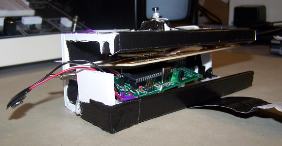
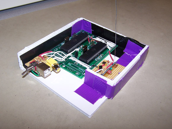
The entire base unit is powered by the 5V signal provided by the USB cable. Therefore, power supply ports, power switches, and power regulators need not be soldered to the two custom PCBs. An LED was connected to pin D.2 of the RX MCU to indicate power, but no LED was connected to the USB MCU because the D.2 pin is required for USB D+ interactions, and an LED would ruin its operation. This pin in specific is required, as it functions as the high-priority external interrupt (INT0) signal. A half-open box was made for the base unit from a foamboard. Photos are shown in Appendix A: Photographs.
Software Design
All code can be found in Appendix B: Software Code.
Transmitting Unit
The transmitting unit code consists of two files. First, there is a txrx.c support file. This was originally a file created by Meghan Desai in 2005 2006 for an ATmega32 microcontroller, but then converted by us to run on an ATmega644. Details about the functions in this code can be found on Desai's project page, and the actual code he wrote can be found at the bottom of that page. The two functions used in the TX MCU are the txrx_init() function, which enables the USART hardware needed to transmit data to the RCT-433-AS chip, and the tx_me() function, which, when given a data array, converts the data into a data packet and places it in memory where a USART0 Data Register Empty ISR can send it over USART to the wireless transmitter. The wireless packet format shown in Figure 9 is used.

The first four bytes of this packet are a repeated 101010... pattern for synchronization purposes. The byte at index 4 is a start character, which used to be 202 in Meghan Desai's code, but we switched it with the encoded value for the nibble that used to represent a data 3 value (149) for a little bit of interference shielding. The byte at index 5 is a transmitter ID, which is left unchanged from Desai's demo program. Bytes 6 and 7 contain the length of the packet's data segment, which is 16 bytes after encoding, or 8 bytes of data. Bytes 8 through 23 are data bytes. Byte 24 is the stop character.
Data is encoded by converting each nibble of data into a byte. This byte has an equal number of 0s and 1s, and there are never more than three 0s or three 1s in a row. So, theoretically, it should be possible to transmit a byte of data with two bytes wirelessly. However, when we were experimenting with a wireless receiver created and left behind by Meghan Desai, we found that it would only print values from 0 to 15, even when receiving two bytes wirelessly instead of one (that is, one byte of data with a range from 0 to 255, not a nibble). Speed in our design was not so timing critical that redundant bytes were an issue, so we decided to send two bytes per nibble of data. The first two bytes of data always encode the number 6 for extra interference shielding. The next two bytes encode the button mask of the mouse, which is a nibble represented in binary as 0xyz, where x is set if the middle button is pressed, y is set if the right button is pressed, and z is set if the left button is pressed. The next four bytes of data encode the tilt in the x direction, or how much the mouse should move due to this tilt, with the low nibble being encoded first. The next four bytes encode the tilt in the y direction, and the next four encode the change in the mouse wheel, but since our handheld device has no wheel equivalent, the change in the mouse wheel is always 0. The transmitted packet could certainly be optimized if there were no dWheel value, and only one byte was used for each the dx and dy values, but such a change would not noticeably affect the functional performance of the device, and the current design leaves open a possibility for extending the handheld device with a wheel feature.
The second code file used in the transmitting unit is called transmitter.c, and it is the main driving program in the handheld unit. The logical structure of this program can be outlined as follows. First, the program initializes its hardware. Port A and C are set up as inputs to receive accelerometer and pushbutton data, and port D is set up as an output for the LED and USART TX pins (although the latter is unnecessary, as the USART takes precedence on that pin). The wireless functions and USART hardware are initialized with the txrx_init() function. Timer0 is set up to generate comparison interrupts every 1ms, and Timer1 is set up to run at 15625Hz. These timers are later used to establish 17ms and 16.384ms time intervals. Finally, the ADC is configured, and the program switches to an infinite main loop. There is no reason why the specific values of 17ms and 16.384ms must be used. We first created the code with Timer1 to take measurements at approximately 60Hz (rather, 61.0Hz). Desai's demo program had the Timer0 example set up to control the transmission cycle period in ms. When we tried 17ms to create a period also close to 60Hz, it worked, and so we no longer had to change that aspect of the code. As a result, both timing methods are still included. The reason why the Timer1 code is not set up to trigger an ISR is because our prototype prior to wireless used one MCU to handle both USB and accelerometer functionality, and USB needed priority, so no other interrupts were enabled.
Approximately every 17ms, the TX MCU gets ready to transmit the current state of the mouse by using the tx_me() function. Approximately every 16.384ms, it updates the state of the mouse. This process consists of reading the output of the ADC, then switching its input to the other channel (x or y accelerometer) and beginning a new ADC conversion. Because ADC conversions take less than 2ms, it is possible to probe accelerometers at the mentioned period for a frequency of about 61.0Hz. After reading the accelerometer input, a threshold value is subtracted to remove biasing caused by the 2.5V standard output of the MMA2260Ds to represent no tilt. Then, the difference is right-shifted once to remove noise and reduce sensitivity, and the result is the desired change in x or y of the mouse position per USB interrupt corresponding to the current tilt of the handheld unit. The state of the mouse buttons must also be updated, so the pushbuttons are read. Pushbuttons are debounced by comparing the current voltages on the input pins to the previous values from 16.384ms ago, and only updating the reported debounced values if they remained the same. Two of the buttons behaved oppositely from the desired behavior (for them, being pushed meant a logic high), so we added an XOR instruction to software when reading their value to quickly reverse their reported behavior. Finally, the LED on pin D.2 is also toggled every 16.384ms, for a 30.5Hz flicker.
When creating an AVR Studio project for the TX MCU code, it is proper to only include transmitter.c, but to place txrx.c in the same directory.
Base Unit
RX MCU
The code used in the RX MCU consists of two files. The first is the same txrx.c file that contains helper functions used in the transmitting unit. The second is the RX MCU driver program, receiver.c, which utilizes the rx helper functions. The logical structure of this program can be outlined as follows.
First, the program initializes hardware. It sets up port B as an output for the data transfer between the RX MCU and USB MCU, and it sets pin D.2 as an output to control the LED. Timer1 is set up to run at 250KHz to later establish a 1ms time base. The wireless variables and USART hardware are set up by calling the txrx_init() function, and finally, other variables are initialized before beginning the main infinite loop.
The main loop always checks to see if the USART has finished receiving a wireless packet. This check is done using the helper functions created by Meghan Desai, downloaded from the bottom of his project website and modified for the ATmega644. The important thing to note is that the data receiver over USART is the same packet that was transmitted shown in Figure 9, but without the first three bytes. The init_getrx() and get_next_rx_data() helper functions are then used to transfer the received data into a byte array shown in Figure 10, called my_rx_data in the receiver.c file. Note that there are additional bytes after the last data byte, up until the specified maximum length of the array, but they are ignored.

Also note that although the data is stored in a byte array, the top four bits of each byte is ignored. The last seven bytes of data are stored in a structure called the txrx_usb_buf_t, and they are assigned a 3-bit address from 001 to 111 in order, which is written to their top three bits (recall, the top four bits are unused). Every 500ms, the LED on pin D.2 is toggled for a 1Hz flicker, and if no wireless packets have been received in the past second, the mouse movement and buttons are zeroed, as it is assumed that the transmitter device has been powered off.
Data is transferred between the two MCUs in the base unit with the following protocol. The RX MCU writes a binary number to port B in the format xxx0yyyy. The value of xxx is the 3-bit address of the data, and the value of yyyy is the value of that data. For example, the button mask is stored at address 001, and dyL is stored at address 011. After the USB MCU reads the value of port B, it will update the top three bits of port D to match the address of the received data. The RX MCU will not change port B again until the top three bits of port D match the top three bits of port B, and the RX MCU will always send the seven data values one after another in order.
When creating an AVR Studio project for the RX MCU code, it is proper to only include receiver.c, but to place txrx.c in the same directory.
USB MCU
The code used in the USB MCU is much more complex. It includes the V-USB code created by Objective Development and distributed under the GNU GPL versions 2 and 3. We used the August 22, 2009 version, which can be downloaded from this page. The only code files that we created were usbinterface.h, usb.c, and drawRoutines.h, and the first two of these also use code from Objective Development's HID mouse example, included in the V-USB download.
The file usbinterface.h contains a structure declaration for storing the mouse status data, as well as a hard-coded ROM in program memory to store USB device information.
The file drawRoutines.h contains variables and functions for storing and modifying the screen buffer to be streamed to the TV. Many of these functions were taken or modified from the ECE 4760 Lab 3 video_codeGCC644 example. The code was originally designed to stream a 144x200 pixel image to the TV, but storing a pixel image of that size required 3600 bytes of data memory, and the ATmega644 only has 4096 bytes of data memory. Since Minesweeper does not require a very fine resolution, we conserved resources by storing a pixel image that is only 72x100 pixels. We accordingly edited screen-modifying functions that were based on x-y pixel coordinates, we changed the assembly routine that streams a line of pixels so that it streams half as many pixels but twice as long, and we later changed the ISR in the driver file usb.c so that it only streams half as many lines of pixels, but it streams each line twice. We also changed the function for plotting small characters to the screen so that it does not need to plot them at x locations divisible by 4, and we added functions that could plot sprites to the screen. The sprites used in the game are shown in Figure 11.
We made these sprites in MS Paint. They are each 8x8 pixels stored in program memory as 8 characters each. They have associated sprite numbers, or indices when accessing them in memory, where the top-left sprite is sprite number 0, and they are numbered from left to right, then by row, up to sprite number 15. The first two sprites are used for drawing the white and black parts of the cursor, the next sprite is an unclicked tile, the next is a highlighted tile (from holding the left mouse button over the tile), the next is a flagged tile, then a revealed mine, then a clicked mine, and then a blank tile after being clicked. The next row of sprites contains numbers that replace clicked tiles with no mines themselves, but with neighboring tiles that have mines.
We created a general method for drawing or undrawing any 8x8 sprite by XORing the white pixels to the screen buffer. We also created methods for specifically drawing and undrawing the cursor sprite. To draw the cursor sprite, the white pixels in sprite number 0 are drawn as white to the screen, and the white pixels in sprite number 1 are drawn as black to the screen, but the previous values of the pixels on the screen are first backed up. When undrawing the cursor, the backed up pixels are simply restored. Finally, we also created a method for quickly drawing a 3-digit decimal number to the screen to be used to draw the counting timer. This method is much faster than converting the number to a string and then plotting the string.
The main driver program is implemented in usb.c, and it has two main modes of operation USB or TV. When the program begins, it calls an init() function that sets up hardware and software. Port B is made an input to receive data from the RX MCU, pins C.5 and C.6 are made outputs to stream video, pin C.0 is an input for the mode select switch, and the top three bits of port D are made outputs to send acknowledgements to the RX MCU. Timer1 is set to run at full speed with clear-on-match to establish video line timing, the watchdog timer is set to interrupt every second for the USB program, and the Random Number Generator (RNG) is seeded.
Then the program enters a main infinite loop that executes whenever switching between the two modes of operation. The function always calls a reinit() function, which in turn may connect the USB device or call the init_game() function. Then the main loop calls either the main_game() or main_USB() function, which themselves contain infinite loops that must use break statements when switching modes of operation so that control returns to the first main loop to reinit again.
When the program is prepared for USB mode, the Timer1 compare interrupt is turned off, the watchdog timer is reset, and the USB device is connected. The USB is managed through a watchdog interrupt. Data to be transmitted to the computer must be prepared prior to the interrupt, and when the interrupt occurs, that data is sent. The transmitted data includes a four-byte packet describing what the mouse's behavior should be, including its button mask, change in x position, change in y position, and change in wheel position. The interrupts occur at approximately 31.25Hz.
In the infinite loop of the main_USB() function, the following events are completed each iteration. The watchdog timer is reset, the USB software is polled, and if the previous data has been sent to the computer, the data to send is updated based on the current state of the mouse. For stabilization effects, when a mouse button is being held, the state of the mouse is reported as not moving two times out of three. This reporting method reduces sensitivity of the mouse when clicking in order to make it easier to click without accidentally dragging the cursor. The current state of the mouse is updated each iteration of the loop by reading the address on the top three bits of port B, writing the appropriate data, and echoing the received address on the top three bits of port D. After receiving from port B, the input on pin C.0 is checked, and if the mode of operation has changed, a break statement is used to exit to the original main function to reinit.
When the program is prepared for TV mode, the Timer1 compare interrupt is turned on, the watchdog timer and watchdog reset flag are turned off, and game variables are initialized. The game field uses helper functions to populate ten randomly selected tiles with mines (as chosen with an RNG) and calculate what numbers should be uncovered for each tile when clicked. Tile status is stored as one byte per tile, which the top nibble being 0, 1, or 2 for unclicked, clicked, or flagged, respectively, and the bottom nibble stores 0xF if a mine is buried there, or a number from 0 to 8 if a mine is not buried there but there are a corresponding number of mines buried in surrounding tiles. The screen buffer is cleared and drawn with the start-up information and unclicked tiles, and the cursor is drawn.
In the infinite loop of the main_game() function, the following events occur. First, the MCU is put in sleep mode, and only awoken when the Timer1 compare ISR is triggered. This establishes timing so that the body of the loop is only executed once per video line streamed to the TV (the ISR itself is what streams pixels to the TV, but only for 200 lines, 100 of which are repeats). Every cycle, the input from port B and pin C.0 are checked the same way as in main_USB(). However, the game state only updates every 60Hz, between streaming frames to the TV, because if the ISR were to be triggered while not in sleep mode, the timing might be thrown off depending on the currently executing instruction, and so no time-consuming calculations can occur any time when pixels are being streamed to the TV.
When updating the game state, the first thing that happens is to undraw the cursor from its previous position and calculate its new position based on the mouse state. If the middle and right mouse buttons are both down, the game resets. Depending on the game state, different things may then occur, but the last thing to happen is to draw the cursor in its new position. Aside from when the game state is 0, the game will simply be calculating or drawing cascade, losing, or winning effects. In game state 0, which is the state when the user has control of the game, the follow events occur. First, the second counter in the top-right of the screen updates. Then highlighted tiles (tiles the user has moused over and held the left button down) are drawn or undrawn. Then clicked tiles (tiles the user has moused over and released the left button on) are drawn or undrawn. If a tile was clicked, the game state may change depending on if the tile sets off a cascade or was hiding a mine. Afterward, flagged tiles (tiles the user has moused over and released the right button on) are drawn or undrawn. Finally, a winning condition is checked (if only ten unclicked tiles remain), and the game changes state if the user has won.
When creating an AVR Studio project for the USB MCU code, it is proper to only include usb.c, usbdrv.c, usbdrvasm.S, and drawRoutines.h, but to place the other files in the same directory.
Previous Attempts
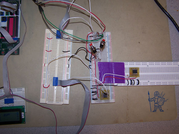
When we were building our device, we worked incrementally from the basic function (USB mouse) to additional features. We started with one ATmega644 on an STK500, and we modified the V-USB code to create a USB mouse that moved automatically in the shape of a diamond on screen. After that, we added the accelerometers and arrived at the circuit shown in Figure 12. We originally had planned to use accelerometers by integrating acceleration to find the change in position, but the accelerometers were not sensitive enough to detect the gradual movement of a mouse, and the signals were too noisy. As a result, the mouse pointer would move around without moving the mouse unit. We tried adding a velocity decay factor that stopped the mouse from moving on its own, but we were then unable to move the mouse significantly by sliding it. However, we did notice during those tests that the mouse was much more responsive to tilting, and so we quickly realized that we would have to switch to a mouse that uses the accelerometers to detect tilt and use that to control the mouse pointer.
After having a working design with the accelerometers, two pushbuttons, and the USB connection, we began designing the circuits on solderboard for a split transmitter/base unit design. This design could not be tested on whiteboards because the intrinsic capacitance between holes causes shorts at the wireless frequency of 433.92MHz. After we separated the design, the USB stopped working, but this was because of loose connections and accidental shorts. We burned out one Zener diode during this time, and it had to be replaced.
After getting the base unit, which then only had one MCU, to once again run the automated diamond mouse program over USB, we tried to introduce the wireless aspect into the software. We had the transmitter unit sending the automated diamond mouse instructions over the wireless connection with 1 packet per second. We noticed that our program no longer worked. After probing the sent and received signals and comparing our program's behavior with that of a reference receiver left behind by Meghan Desai, we determined that the problem was the low frequency of transmissions. If the RCR-433-RP has not received a packet in a long time, it readjusts its gain and searches for packets that are not actually there. As a result, it picks up packets that do not exist and misses some packets that do. When we increased the frequency of our transmissions to 10Hz, the receiver could pick up every packet and did not adjust gain in between packets.
However, at that frequency, the USB stopped functioning properly. We read the documentation from V-USB and learned that the USB interrupts must have highest priority to meet timing constraints. The frequent USART interrupts triggered by the wireless receiver were preventing the USB interrupt from executing. There was an impossible tradeoff where if the transmitting frequency was too low, the wireless would not work, and if the transmitting frequency was too high, the USB connection would fail. We solved this problem by adding another microcontroller, separating the base unit into the RX MCU and USB MCU so that one handles the wireless data coming in, and the other communicates with the computer through USB.
From there, we suffered from more faulty wiring issues, which we debugged by probing the circuit. Afterwards, we tested having the USB MCU run the automated diamond mouse program, and when that was working, we tried having the RX MCU run the program and have the USB MCU relay it to the computer. This failed, as the cursor would often miss instructions. The reason was that we had originally tried to implement an exchange protocol between the RX MCU and USB MCU based on timing instead of acknowledgement signals, but the interrupts were making the timing unpredictable. When we added the port D acknowledgements, this issue was resolved.
After that, we tried having the TX MCU run the automated diamond mouse program and transmit it wirelessly in packets at 58.8Hz to the RX MCU, which then relayed it to the USB MCU, which then relayed it to the computer. There were no problems with this step. Finally, we tried to have the TX MCU read the accelerometers and pushbuttons and transmit that information instead. For some reason, the transmitted tilt information was always to move the mouse in the x and y direction by -1. When probing the circuit, we could see that the accelerometers were outputting good analog voltages. This led us to believe that our ADCs were not functioning correctly. When we implemented the same design on an STK500 and whiteboard, the ADCs read the correct values, so the problem was that the same program running on an STK500 did not do the same thing on the custom PCB. After reading the datasheets for the STK500 and ATmega644, we learned that the problem was that we had set Aref to the external voltage, which in the case of the STK500 was jumpered to Vcc, but in the case of the custom PCB was connected to gnd. So, we changed the software to set Aref to AVcc, which solved the problem.
We then encountered issues with the left and right mouse buttons behaving differently from the middle and top mouse buttons. We debugged these issues by having the LED on the handheld unit show the status of each mouse button, and we learned that the pushbuttons were wired oppositely. We solved this problem by XORing those respective bits after inputting them.
Finally, when testing the complete mouse design, we noticed that it would sometimes move the cursor randomly or cause buttons to press without anyone pressing the pushbuttons. We thought these effects were due to wireless interference or a problem in the RX MCU to USB MCU communication. After modifying the wireless protocol to lessen interference effects, and after adding quadruple redundancy to the RX MCU to USB MCU communication, the errors still persisted. However, we noticed that the errors only occurred when the handheld unit was powered by a battery, and not when it was powered by a 9V signal from a protoboard. We measured the battery and found that it was only outputting 7.5V. After replacing the battery with a new one, the mouse behaved properly.
Any further issues in USB mode related only to the mouse's sensitivity, which we solved by right-shifting inputs or only reporting every third state when a button is held. As for TV mode, there were various issues relating to small software bugs, and the TV would flicker because there was a faulty ground connection. Otherwise, there were only two large problems with our initial Minesweeper program.
First, the game would reset every second. This was a result of the watchdog timer, which had been set for USB mode. Even after disabling watchdog interrupts with the watchdog timer control status register, the resets persisted. After reading the ATmega644 datasheet sections related to the watchdog timer more carefully, we learned that we also needed to clear the watchdog reset flag in the MCU status register. Doing so whenever setting up for game mode solved the problem.
Second, the game would sometimes draw random pixels to various parts of the screen. This turned out to be a timing issue, as the game was only able to undraw and draw six tiles between two adjacent frames, and trying to draw more than six would result in errors. We restructured our code by adding extra drawing states and reducing the amount of drawing per iteration.
Results
Speed
Once we added the additional microcontroller for the base unit, there were no timing issues. Accelerometer reads and wireless transmissions occur at about 60Hz, communication between the RX MCU and USB MCU happens continually during each MCU's main loop (full exchange can happen on the order of microseconds), and the USB is updated at about 31Hz. Overall, there is a noticeable response time on the order of milliseconds between tilting the mouse and seeing the desired effect on screen, which still feels natural. When the USB MCU is in TV mode, there is a noticeable split-second lag when clicking a square that has no buried mine and no neighbors with buried mines. This is a result of cascade computations, which theoretically can cause tiles in opposite corners of the game field to be clicked in one cascade. Since the program can only redraw six tiles per frame, and there are 81 tiles in the entire field, a worst-case scenario would be about 14 frames of drawing, and at 60Hz this means a quarter-second for the entire cascade. As this is just a game, the time lag is not critical, and we compensate by halting the game second timer when cascades are occurring.
Accuracy
The mouse can be fairly accurate with a little practice. Originally, the sensitivity from directly reading accelerometer values was too high, so we reduced it by right-shifting a few times (effectively dividing the tilt effect by a power of 2). It is important to calibrate the device in a natural position so that it is easy to hold the mouse pointer still. Even when still, the cursor sometimes moves, because the accelerometer is often calibrated in a position in between discrete steps - that is, the accelerometer can alternate between different discrete values to average to an in-between value, but since calibration can only choose one of those discrete values as the zeroing point, the mouse will sometimes move when the accelerometer reports the other. An issue we noticed during initial testing was that it was difficult to click a point and then release the mouse button while still over that point. This is an important action, because if a user presses the button, then moves the mouse, then releases the button, the computer will infer a dragging motion instead of a single click. We solved this by reducing the sensitivity when a mouse button is being held, and it is now much easier to click while staying still, although it may still require a bit of practice from a new user.
Safety
There are not many safety concerns with our project. The highest voltage is a 9V battery, which is not enough voltage to pose a safety risk. The battery and all circuits are enclosed in boxes to protect the user from any possible injury. Proper soldering techniques were followed to prevent lead exposure and any other harm associated with soldering, and the foamboard boxes prevent users from having to touch any solder with their hands. The boxes are still left open on at least one side for power dissipation purposes to eliminate fire hazards, although the power of the devices is already low enough that it should not be a danger. The antenna in the handheld unit was bent into the box to prevent poking anyone, and the antenna on the base unit was bent to lower the risk of accidental injury on the sharp end of the wire.
Interference
The mouse is using a 433.92MHz transmitter and receiver, so it receives interference from other wireless devices in the 433MHz range. To prevent interference to the mouse receiver from other devices, especially other ECE 4760 projects, we used a wireless protocol with a transmitter ID (encoded 3), a different start character from Meghan Desai's default code (149), and an extra byte (encoded 6) to confirm that the packet was sent from our transmitter. During testing, we have seen glitches when the distance between handheld unit and base unit was greater than a foot. Depending on the lab conditions, at a distance of five feet the device could become annoying to use. Still, it has been more probable to pick up false information from our own transmitter with a broken 7.5V battery or when initially turning the transmitter off. Because of the limited applications of 433MHz signals outside of the ECE 4760 lab, we do not anticipate many interference problems.
Usability
The mouse becomes fairly easy to use with a little practice. Our prototype is designed for a right-handed person and would be more difficult to use for a left-handed person. This could easily be fixed with different packaging, but we only created one prototype of the mouse, and it was a right-handed version. It would also be beneficial to make the overall size of the transmitting unit smaller so that it would fit in one's hand better. The current design is large and a bit left-heavy, but the size could be reduced by creating a custom printed circuit board (PCB) so that smaller components could be mounted in a way to take up the least amount of space. Persons who cannot use a regular handheld mouse as a result of arm-related disabilities will not be able to use our device.
Conclusions
Meeting Expectations
There is less stability than with a traditional mouse because the user holds it in the air instead of resting it on a flat surface. It can become tiring to hold it in the air and try to keep it still, but when giving a presentation, a great amount of time the mouse can drift to a corner and stay there without consequence, and if using the mouse at a regular desk station, one can always use it by resting it on the table and tilting it back and forth and from side to side. When interference is low, it is still more convenient for situations where the user is not at a desk or flat surface, but the stability at a distance fell short of our expectations when interference was high, and so our range is smaller than ideal. The box is rather big and awkward to hold for people with smaller hands, but it could easily be made smaller by creating a small custom PCB for it. Overall, the movement of the mouse pointer worked very well, conditional on a working battery and low interference. It is smooth and accurate, without jumping around unexpectedly. However it does take a little practice to get good at using. The Minesweeper game worked well as a further demonstration of the mouse's use. The game played well without timing jitters or control issues, and all functions were tested to work.
Standards
We do not claim that this device meets USB or NTSC standards. However, we have tested the device on several computers, including ones with Windows and Linux operating systems, and two types of analog TVs, and in all cases, the respective computer or TV was able to recognize and interpret the transmitted signals as they were intended.
For wireless standards, consult the Legal Considerations below.
Intellectual Property
Did you reuse code or someone else's design?
Yes, we reused the V-USB code and the suggested hardware design for the MCU to USB communication using Zener diodes. We also used code and hardware designs from Meghan Desai's wireless project for our wireless protocol and communication, and we used code and hardware from the ECE 4760 Lab 3 video_codeGCC644 example for NTSC-like video streaming.
Did you use code in the public domain?
Yes, V-USB is in the public domain and distributed under the GNU GPL versions 2 and 3. Meghan Desai has consented to allow ECE 4760 students to build off his code.
Are you reverse-engineering a design? How did you deal with patent/trademark issues.
We have not reverse-engineered an existing design. USB is a trademarked term, and we dealt with it by not claiming our device to be USB compliant. We have not entered into any agreement to obtain our own Vendor ID or Product ID for this device.
Did you have to sign non-disclosure to get a sample part?
No.
Are there patent opportunities for your project?
Since our project uses software licensed under the GNU GPL, we cannot patent the software. We have searched for, but not found, any pre-existing patent for a tilt-based accelerometer mouse in the United States. However, pursuing a patent on this design would be unwise considering that it is in violation of wireless FCC regulations. Further revisions would be needed before considering a patent.
Are there publishing opportunities for your project?
Once again, the violation of FCC regulations will limit acceptance of this design. Further revisions would be needed before considering publication.
Ethical Considerations
Our project does not pose any ethical controversies, and all decisions were made in accordance with the IEEE Code of Ethics. We have limited the possibility of health or safety risks to users by enclosing the devices in foamboard boxes that protect users from lead exposure or electrical currents. The wireless strength is low enough that there would be no harmful effects to the user or society. There are also no conflicts of interest related to our involvement with this project; it was designed for the sole purposes of being a learning exercise for ECE 4760 and exploring the possibility of a useful new mouse design. To our knowledge, all of the claims made in this report and any other documentation referenced in our project are accurate and honest, and we have limited our reported results to what we have observed. Through this project and report website, we strive to improve both our own understanding of technology and its application, as well as that of any readers of this website or future students of ECE 4760, specifically with regard to the USB standard and wireless transmissions that are relevant to this project. Our limitations as young engineers and our general inexperience with many technologies associated with our project were fully disclosed and known by all interested parties, and we do not attempt to claim expertise over the topics discussed. All of our sources have been properly acknowledged and credited. Our design treats all persons fairly and does not intend to discriminate against any group of people. Although our prototype implementation was designed for right-handed testers, a simple and feasible physical redesign makes it just as possible to create a left-handed version. There was no willingly false or malicious action associated with the design or operation of our product. Throughout the project we were always willing to help other groups by explaining how our project works.
Legal Considerations
Our design is in violation of the wireless FCC regulations pertaining to devices transmitting periodically in radio frequencies above 70MHz without a license. These frequencies are reserved for alarm systems, door openers, remote switches, etc., and it is not permissible to transmit at regular predetermined intervals. Specifically, the wireless range from 433.5MHz to 434.5MHz is restricted to devices that use radio frequency energy to identify the contents of commercial shipping containers, which our device does not do. However, our antennas are so deoptimized that the effective range of transmission is approximately 20 feet, and so our prototype in unlikely to cause any interference, especially considering the intended applications of devices that use this frequency range. Future versions of this device should use an unlicensed frequency band.
Possible Improvements
Our device could be made FCC compliant by using a wireless transmitter and receiver that operate in an unlicensed frequency band, such as the 2.4GHz frequency used by many other ECE 4760 projects. While redesigning the wireless circuitry and protocol, it would also be possible to achieve a more robust design (less interference).
Our current design is inefficient with regards to the amount of computing power available. A wireless mouse base unit should not require two microcontrollers, nor even one, if we instead had access to custom hardware that could receive wireless transmissions and interact with the computer in parallel. This would disallow the current implementation of Minesweeper, but users can always go to other sources to play this game. Arguably, the handheld unit could also be implemented with custom hardware, which would be a good tradeoff considering the current size of that unit. However, as the purpose of this project was to demonstrate a use for a microcontroller, we were required to have at least one in our design.
Future designs could restructure the handheld device into a more ergonomic shape. Also, a computer mouse is commonly used in conjunction with a keyboard, so it would be interesting to add a feature that allows the user to temporarily disables wireless transmissions without turning off the device in order to quickly switch between using a mouse and keyboard. Assuming a right-handed design, a glove-shaped unit with a disable button on the left side of the index finger would allow a user to type on the keyboard, quickly switch on the mouse and navigate, and then quickly switch off the mouse and type again. However, there are certain sanitary issues that arise from an actual glove-shaped mouse, but some other, open form of hand-mounted design would be equally effective.
Appendix A: Photographs
Appendix B: Software Code
TX MCU Code
When creating an AVR Studio project for the TX MCU code, it is proper to only include transmitter.c, but to place txrx.c in the same directory.
RX MCU Code
When creating an AVR Studio project for the RX MCU code, it is proper to only include receiver.c, but to place txrx.c in the same directory.
USB MCU Code
When creating an AVR Studio project for the USB MCU code, it is proper to only include usb.c, usbdrv.c, usbdrvasm.S, and drawRoutines.h, but to place the other files in the same directory.
Appendix C: Hardware Schematics
Custom PCB Schematic
This shows the hardware connections on the ECE 4760 custom PCB, which is discussed in the hardware design section. Only the TX MCU has all of the connections shown. The RX MCU and USB MCU do not require the power regulator circuitry, and the USB MCU must not have the LED circuitry.
Transmitting Unit Schematic
This schematic shows the hardware connections linking the custom PCB with the TX MCU on it to the accelerometers and wireless transmitter.
Base Unit Schematic
This schematic shows the hardware connections linking the custom PCBs with RX MCU and USB MCUs on them with each other, the wireless receiver, and the USB and TV circuitry.
Appendix D: Cost Details
| Part No. | Part Name | Quantity | Cost | Source |
| ECE 4760 Custom PCB | 3 | $12.00 | ECE 4760 Lab | |
| ATmega644 | Atmel Microcontroller | 3 | $24.00 | ECE 4760 Lab |
| 6" Solder Board | 2 | $5.00 | ECE 4760 Lab | |
| RCR-433-RP | Radiotronix Wireless Receiver | 1 | $4.00 | ECE 4760 Lab |
| RCT-433-AS | Radiotronix Wireless Transmitter | 1 | $4.00 | ECE 4760 Lab |
| CC089 | Velleman USB B Female Single Connector | 1 | $0.98 | Parts Express |
| USB Type A to Type B Cable | 1 | - | Pre-owned | |
| B/W TV rental | 1 | $5.00 | ECE 4760 Lab | |
| RCJ-6Y | Right-angle PCB Mount RCA Jack | 1 | $0.10 | All Electronics |
| VMC-12 | 12' RCA Plug to RCA Plug, Co-ax Cables | 1 | $2.25 | All Electronics |
| 9V Battery Clip | 1 | $1.00 | ECE 4760 Lab | |
| 9V Battery | 1 | $3.00 | Kmart | |
| MMA2260D | Freescale Semiconductor Single Axis Accelerometer | 2 | Donated | ECE 4760 Lab |
| 20"x30" Foamboard | 1 | $2.99 | Michaels | |
| Resistors, Capacitors, Inductors, Zener Diodes, Wires, PCB components, etc. | - | ECE 4760 Lab | ||
| Total | $64.32 |
Appendix E: Task Breakdown
| Task | Group Member |
| Created initial hardware design. | Jack |
| Wrote automated diamond mouse program. | Skyler |
| Debugged USB D+/D- pull-up resistor problem. | Jack |
| Wrote preliminary tilt-based accelerometer program. | Skyler |
| Soldered custom PCBs. | Jack |
| Soldered split TX/RX boards. | Skyler |
| Debugged wireless communication / USB interrupt problem. | Both |
| Designed RX MCU / USB MCU data exchange protocol. | Jack |
| Implemented split TX/RX/USB software. | Skyler |
| Debugged accelerometer Aref=AVcc problem. | Jack |
| Implemented Minesweeper and dual-mode USB MCU software. | Skyler |
References
Datasheets
Vendor Sites
Code/Designs Borrowed from Others
V-USB August 22, 2009 version for HID mouse example.
V-USB Hardware Considerations for Zener diode USB circuit.
Meghan Desai's Wireless Project for wireless transmission protocol and circuit.
ECE 4760 Lab 3 and video_codeGCC644 Example for NTSC-like video streaming code and circuit.
Background Sites/Paper
Wireless FCC Regulations (Radio Frequency Devices)
Thanks
We would like to thank the following people and organizations.
Freescale Semiconductor for their donation of the MMA2260D accelerometers.
Objective Development for their V-USB code.
Meghan Desai for his wireless protocol code.
Shane Pryor, Bruce Land, and Jonathan Diamond for their video streaming code.
Allison Smyth and the other ECE 4760 TAs for helping us in the lab and keeping it open so we could work.
Bruce Land for instructing the ECE 4760 class about microcontrollers and helping us in the lab.
The designers of all other components we purchased to make our project.