ToneMatrix Touch
by Jane Park, Michael Chin
We can be reached at {jp624 | msc247} at cornell dot edu.
Introduction
The ToneMatrix Touch (TMT, aka Teenage Mutant Turtle) is a touch-based music-synthesis device based on an ATmega644 microcontroller.
We were inspired by a flash application called the ToneMatrix. Fans of the ToneMatrix describe this application as being “simple,” “beautiful,” “addictive,” and “hypnotic.” By bringing this application to hardware and adding on a tactile dimension to allow physical interaction, we sought to create a more interactive version of the original ToneMatrix.
The ToneMatrix Touch features a matrix of LEDs that display the playback state, a touchscreen for user input, and speakers.
Our final product interacts with the user through sight, touch, and sound to create a truly multi-dimensional experience.
High Level Design
Source of Idea: the Original Tone Matrix
The original ToneMatrix is a Flash application featuring a 16 X 16 grid. The user can click on each grid to activate or deactivate it, and the application continuously loops through columns, playing back the combination of notes corresponding to highlighted grids in each column. Since the ToneMatrix uses a pentatonic scale (B, A, F#, E, D), any combination of grids sounds pleasant. Ripples of waves emanating from grids denote which grids have been selected or are being played back.Background Math
Tones are created by using the Karplus-Strong algorithm discussed in lecture which simulates a string being plucked or hammered. An array of white noise is fed into a delay one for each tone generated. The delay line is then fed into a filter, which specifically in this case is a low pass filter that averages adjacent samples.
The output of the filter is then fed back into the delay line creating a positive feedback loop. Therefore, the gain of the filter must be less than one for stability.
Given a desired fundamental frequency Fd, and a sampling frequency of Fs, a delay length of Fs/Fd is required. Intuitively this can be seen as increasing the length of the string being simulated, which corresponds to a lower frequency.
Because the TRT kernel does all the scheduling, delays are strategically placed to try to maintain a constant sampling rate.
Logical Structure
Other
There were no particular standards relevant to our project, and to the best of our knowledge there are no existing patents, copyrights, and trademarks relevant to our project.
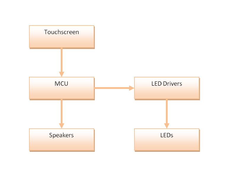
Hardware Design
A single ATmega644 microcontroller interfaced with three main peripherals: the touchpad for input, speakers for audio output, and LED bank for visual output. We had to do ADC conversions to interface to the MCU, and DAC conversions to the outputs.
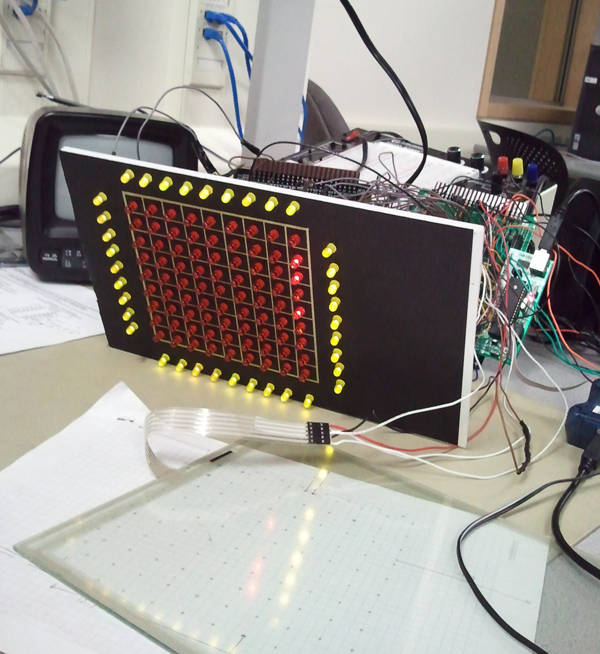
We kept our hardware modular by having three main “panels.” We had one panel designated to the LEDs, another for the resistors for each of the LEDs, and a controller panel where our LED drivers, MCU, and music and touchscreen connections were made. This modularization made it easier to test individual components and to split the soldering between the two of us.
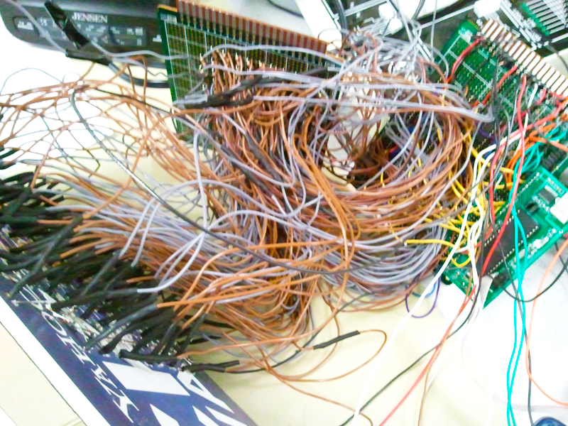
^ Three hairy panels
Touch
A 5-wire resistive touchpad was used to receive user input. Four input wires allow voltage control of each corner. The single output wire connects to the lower layer of the touchscreen, which is where the reading is made. The upper layer behaves exactly likely a voltage divider. When the touchpad is pressed, it creates a connection between the upper and lower layers of the touchscreen, outputting the voltage divided at the upper layer.By alternating between setting the upper corners to high and the lower corners to low, and then swapping so the left corners to high, and right corners to low, we could get the x and y coordinates of a press in terms of voltages. The analog voltages are then converted to digital values using the built in ADC in the MCU. These digital x and y values were then processed by in software.
Sound
Visuals
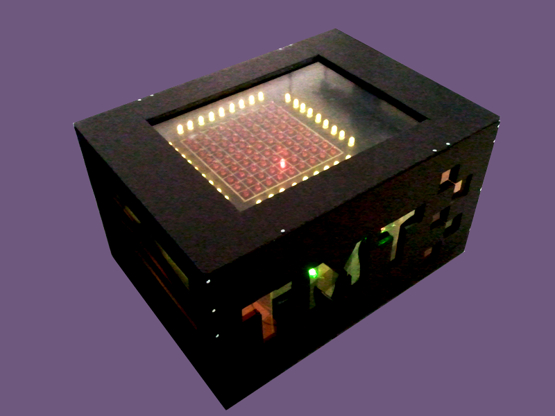
Since our touchscreen is transparent, we were able to overlay it above a grid of LEDs, which each LED in the grid corresponding to a “playing” grid. That is, as the ToneMatrix looped through the columns, the corresponding column of LEDs would lit up. Also, when the grid detects an input, four yellow LEDs--two at the ends of the corresponding column, two at the ends of the corresponding row--light up to verify the input for the user.
We spent many days in lab soldering.
Given that LEDs are rather simple devices, driving an entire grid of more than a hundred of them proved to be a lot more challenging than we anticipated. At first we intended to use charlieplexing, but were not happy with the results when we tried it out on a 4x4 sample grid. The lights were too dim, and we were not happy with the fact that in lighting any single LED, multiple other LEDs would be simultaneously lit, however negligible the brightness of those were. We consulted another group that was driving multiple LEDs, and learned that they were using SIPO latches to drive their LEDs. In our final design, we use fifteen 74HC595 8-bit SIPO shifters to drive the 117 LEDs.
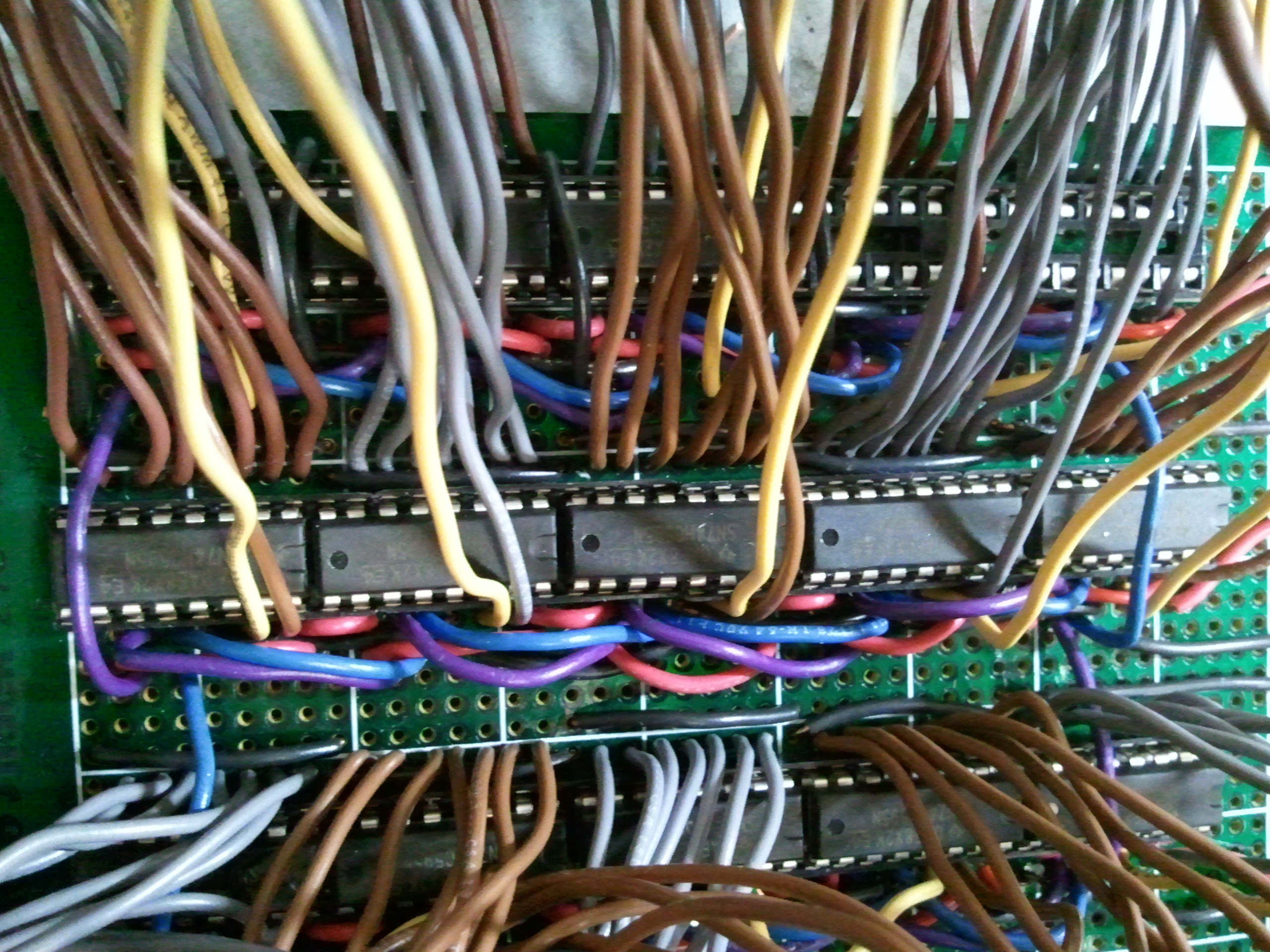
^ The many shifters and wires
We are using a total of 17 MCU pins (1 for shift-clock, 1 for latch-clock, 1 serial input for each chip) to do this.
Although we could have driven all the LEDs with a mere 3 output ports by chaining all the chips together, we happened to have a lot of pins we weren't using on the MCU so chose to use them to decrease the time required for sending in all the LED signals. By directly driving the serial input of each chip, we can shift in bits to the fifteen chips in parallel. If we had chained any of them, all of the bits for all the chips would have to be shifted in in one serial stream.
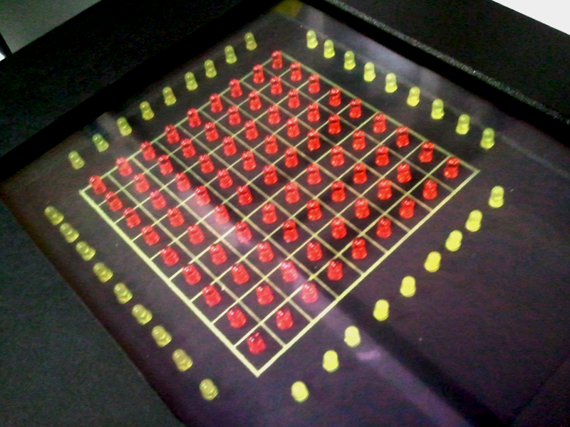
^ The matrix
Other
We were originally going to power the TMT using 9-volt batteries, but changed to using wall power after we realized that batteries were insufficient for lighting up our LEDs.
Software Design
Touch (Input)
We scheduled a routine to continuously grab and process touchscreen input. As described in the hardware section of this report, we toggled the voltages at the corners of the touchpad, and converted the output voltages into x and y values.
The values output by the touchscreen were non-linear. That is, what should be the identical y-coordinates would actually yield slightly different values depending on the x-coordinates.
These x and y values were then mapped to grids of the matrix. To do this, we had to create a table containing the border coordinates of our entire matrix. This was a tedious process, and this mapping scheme is inefficient since the slightest change to the shape or size of the grid would entail re-sampling all the border values for the new grid. The raw x and y values are also dependent on the voltage powering the touchscreen.
Originally, we considered creating some kind of function that would linearize the raw coordinates. But given that we only need to distinguish 81 different locations, we decided such a function would be both unnecessary and too costly.
We also found more advanced touchscreen-controller code from the AVR website which was written for the IAR compiler. This program was capable of measuring durations of touches and provided distinct signals for registering taps instead of just coordinates. Although we spent a full lab period porting over this code to GCC, in the end we found the code too heavy for our needs and not worth the time getting it to work with our particular microcontroller chip.
The touchscreen was insensitive enough that a specific debouncing scheme was unnecessary. It is simply not possible to "accidentally" brush the screen into receiving unintended inputs. As for durations of touches, timing the touch-detection function to be run on intervals was sufficient to prevent a single input from being registered as multiple inputs.
When a valid grid-tap is registered, a table keeping track of grid activity for that grid is toggled so that an active grid becomes inactive and vice-versa.
This required sampling the voltage at the edge of each button in advance. The inputs were then compared against our table of x and y values to map the press to a button. Once a solid button press is recorded the corresponding value in our grid of pressed locations is updated, either enabling or disabling that location.
Sound
We scheduled a routine to update the audio and visual representation of the state of the machine, which is controlled by user input.
We used semaphores to make a local copy of the array keeping track of grid-activeness. Then we iterated over it the matrix column by column for playback. Note that this means that any input registered during a particular iteration of playback is not reflected until the next playback. The original ToneMatrix behaves this way as well.
For each column, we check if the entry in each row is active. If so, the corresponding note is played.
We used the Karplus-Strong algorithm to dynamically synthesize each note. For the string sounds we used the algorithm using two samples, and for the percussion, only one sample. The equation for the frequency is:
Sampling Frequency/Delay Length = Note Frequency
Each of the notes are summed and output to their respective low-pass filters. The low-pass filters are described in the hardware section.
LEDs
The code for controlling the LEDs is somewhat unintuitive. It is intuitive to think of going through the list of LEDs to turn them on or off, but what we are actually doing is traversing the pins of all the shifters, checking which LED was assigned to a particular pin, then deciding whether to send an 'on' or 'off' signal. Since we chose to create a 9X9 grid as opposed to a dimension like 8X8 (power of 2), the LED-to-shifter mappings were somewhat awkward and led to code with a lot of nested case statements that was nowhere near as elegant as we would have liked our code to be.
Exterior Construction
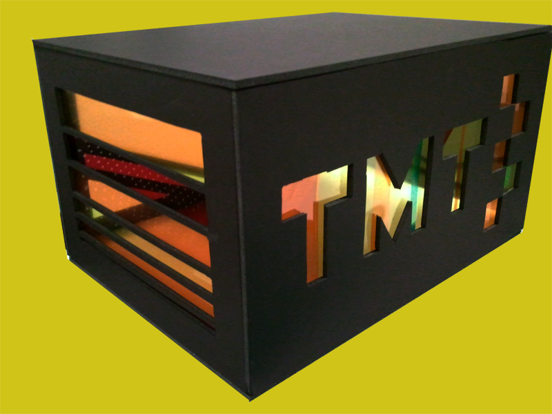
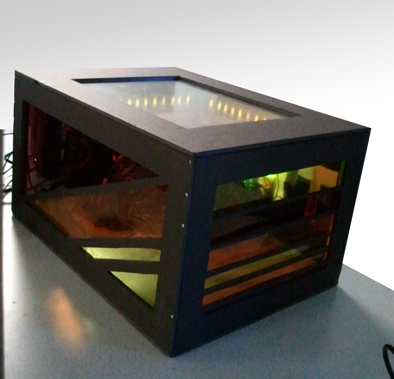
We had too many wires which were both ugly and were rather fragile, so we wrapped everything up in a "stained glass" case that while protecting our hardware, also allowed people to see inside (we wanted people to see our hours of pain).
^ Empty case (left) and everything that went in it (right)
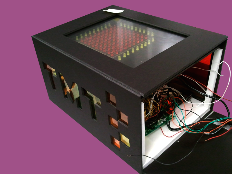
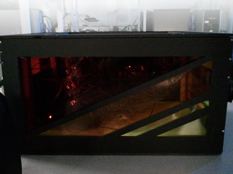
^ Before getting sealed up
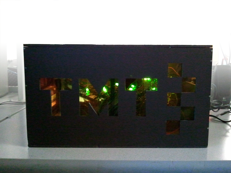
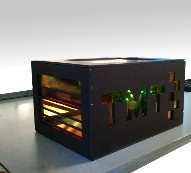
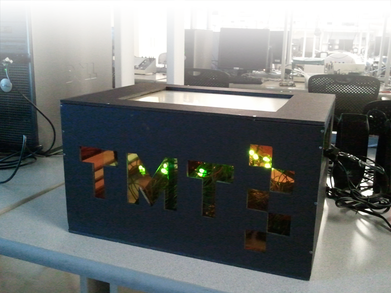
^ Front view (left) and back view (right)
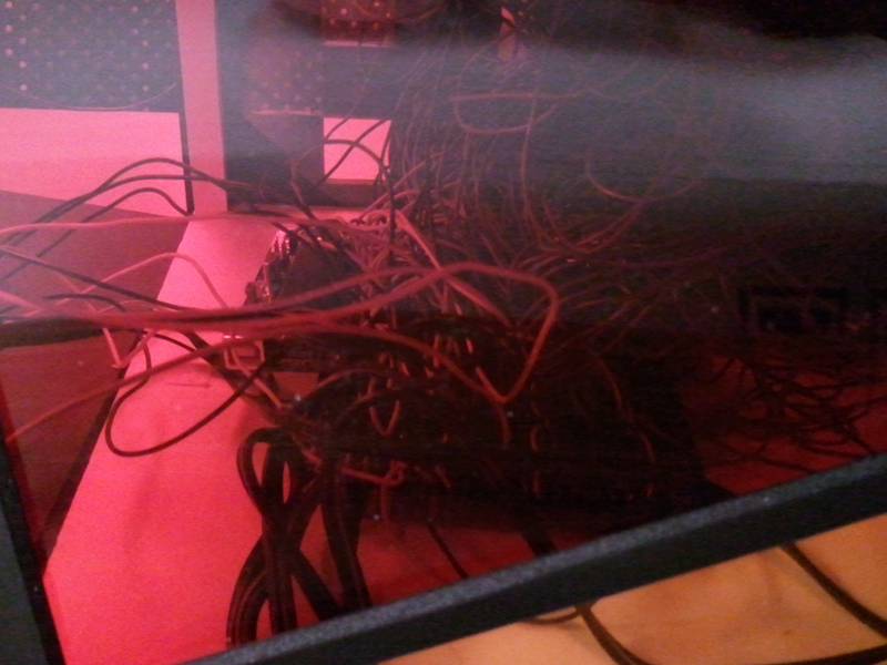
^ View through a window
Results
The music tones generated were not tuned to any particular frequency. The tones were "tuned" by arbitrarily increasing and decreasing time delays and checking by ear to see if they sounded pleasant.
Upon detecting a valid touch in the grid, the "focus" LEDs on the border corresponding to the column and row of input turn off to verify input. This feature doesn't quite have the "instantaneous" effect we would have liked to have, since LEDs can be updated only every so often. There is a slightly noticeable lag, but the feature still functions as desired. Since there was no easy way of creating the "ripple-wave" effect from the original ToneMatrix we chose "border-focus" LEDs to indicate input independent of which column is being played back.
The touchscreen input-to-grid mapping is not completely exact. The behavior of the matrix on inputs that are close to the borders dividing grids is not specified. This should not be a big problem, since we expect users to tap inside the boxes, not the borders. Occasionally, there are cases where an input that lies within borders of the matrix are not mapped to any grid, in which case the mapping defaults to grid (0, 0). These rarely occur, however, and don't cause significant problems since only one input is getting "dropped" out of the user's many inputs.
Since the only physically exposed part of the TMT is the touchscreen and everything else is neatly packed inside our casing, it should be safe for people to use the device.
Our device doesn't have interference issues in particular. It would be difficult to use the TMT, however, should you decide to take this into a crammed subway or a playpen full of balls and random people’s elbows start pushing on the touchscreen. Our device can potentially cause interference to other devices by emitting light and sound.
The TMT doesn't require any "learning" or effort to use and can be used by people of all ages. Unfortunately, people with disabilities who can't hear and/or see would miss out on a component of the device.
Conclusions
We wanted to keep the software functionalities of our project as independent as possible from the hardware specifications such as pin layout. We did this by avoiding directly addressing pins and using a lot of defines instead. But because of our awkward LED-to-shifter mapping mentioned earlier, our code ended up becoming pretty interlocked with the hardware layouts in order to cover special cases.
We had a rather disappointing work-to-outcome ratio, since we spent a significant amount of time doing busy-work (mainly soldering in the 100+ LEDs). All the soldering made us really miss "thinking" tasks.
“This is the problem with n-squared designs," said our instructor Bruce Land when we started worrying about soldering our three panels together. We knew nested for-loops could get pretty costly in software, but had the opportunity to physically experience the cost of O(n^2) designs in this project. Many people who saw our circuit noted how “hairy” it looked. We highly recommend future generations of ECE 4760 to use a PCB if they decide to have this many wires.
We think we could have used smaller resisters--our LEDs were slightly dimmer than we would have liked, though they stood out sufficiently in the dark background of our case. It would have been nice if we could have used RGB LEDs, but they were infeasible for use in this project considering our cost constraints. Had we planned ahead it would have been nice to sample them.
Our touchscreen behaves reliably, but is also disappointingly unresponsive. Alternative touchscreen types such as capacitive should allow for easier interaction with the device. It would be nice to be able to lightly swipe over the grid to have them smoothly light up.
Upon hearing that Jane spent a whole day constructing the casing for our project, a friend said “that’s not engineering!”
Design matters, and electrical engineering projects should be no exception. We did not want to fully expose the naked wires of our project to other people. Circuits need clothes too, and we wanted to create a complete product. We sought to replicate and enhance the user experience of the original ToneMatrix, and to create a truly engaging musical activity we wanted our product to be visually appealing with all wires out of the way.
A mega-scale version of our project would be cool. Giant tiles could correspond to each grid in a matrix where people interact with the matrix by stepping on the tiles.
There were no applicable standards to the TMT.
Intellectual Property Considerations
There are no patent or publishing opportunities for this project, but we copyright the stained-glass circuit case design.
Ethical Considerations
We didn’t play sound that much or play it loudly in lab, but we realize this device can be potentially very annoying if you leave it on with blasting speakers. Please consider the sanity of your neighbors.
Legal Considerations
Appendix
Program Listing
- TMT-main.c
- TMT-global.c, TMT-global.h
- TMT-touchscreen.c, TMT-touchscreen.h
- TMT-music.c, TMT-music.h
- TMT-led.c, TMT-led.h
- trtkernel644.c, trtkernel644.h
- trtkernel644trace.c
- trtSettings.h
- trtUart.c, trtUart.h
- uart.c, uart.h
Schematics

Cost Details
| Part Name | Quantity | Unit Price | Total Price | Source |
| Custom PC board | 1 | 4.00 | 4.00 | Lab |
| RS 232 Connector | 1 | 1.00 | 1.00 | Lab |
| Touchscreen | 1 | 0.00 | 0.00 | Sampled |
| ATmega644 | 1 | 0.00 | 0.00 | Sampled |
| 74HC595 | 15 | 0.462 | 6.93 | Digikey |
| LEDs | 117 | 0.07 | 8.19 | Lab |
| Solder board (6 inch) | 2 | 2.50 | 5.00 | Lab |
| Resistors, capacitors | a lot | 0.00 | 0.00 | Lab |
| Power supply | 1 | 5.00 | 5.00 | Lab |
| Header sockets | 72 | 0.05 | 3.60 | Lab |
| DIP socket | 15 | 0.50 | 7.50 | Lab |
| Foam-core | 1 | 6.99 | 6.99 | Cornell Store |
| PVC sheets | 3 | 2.49 | 7.47 | Cornell Store |
| Brass hinges | 1 pair | 0.99 | 0.99 | Cornell Store |
| TOTAL | 56.67 |
Work Division
| Task | Mike | Jane |
| Integration, Debugging | ✓ | ✓ |
| Music | ✓ | |
| Touchscreen | ✓ | ✓ |
| LED | ✓ | |
| Soldering | ✓ | ✓ |
| Case | ✓ | |
| Website Content | ✓ | ✓ |
| Website Design | ✓ | |
| Sampling parts | ✓ |
More Images
^ "Stained glass"
^ LEDs were placed in the interior
References
Touchscreen
74HC595
Old Projects
Vendor Sites
Acknowledgements
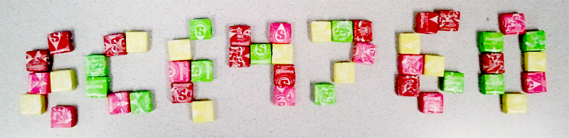
^ We like starbursts, which were always with us in lab.
Mike Zhu: Thank you for distracting us one day in lab to check out the ToneMatrix. If it weren’t for you, we would’ve ended up making an uglier version of touch-based Mario Paint.
Dan Felicetta & Arun Swain: I didn’t know your names until I saw your final project webpage. Thanks for explaining the shift registers to me. Your project’s really cool, by the way.
All lab-mates: Sorry we kind of hogged the soldering station. We had a lot of connections.
Jeff Yates: Whenever we thought of the too-much-time we spent in lab, thinking of how much time you spent in that room made us feel better. Thank you for all the help and encouragement the whole semester. You’re a badass.
Bruce Land: Thank you for doing magic whenever we got stuck debugging, and for all the advice, encouragement, and crazy stories. Thank you also for the Oreos and Nutter Butters. There’s nothing like sugar and fat when you’ve been soldering all morning on a weekend.